Note: Descriptions are shown in the official language in which they were submitted.
CA 03067089 2019-12-12
INFORMATION TRANSMISSION METHOD AND APPARATUS
CROSS-REFERENCE TO RELATED APPLICATIONS
[0001] This application claims priority to a Chinese patent application No.
201710939835.7
filed on September 30, 2017.
TECHNICAL FIELD
[0002] The present disclosure relates to, but is not limited to, the field
of communications.
BACKGROUND
[0003] In Long Term Evolution (LTE for short), a physical downlink control
channel
(PDCCH for short) is used for bearing uplink and downlink scheduling
information and uplink
power control information. The downlink control information (DCI for short)
formats includes
DCI formats 0, 1, 1A, 1B, IC, 1D, 2, 2A, 3, 3A, etc. And later DCI formats 2B,
2C, and 2D are
added to an evolved LTE-A Release 12 to support a variety of different
applications and
transmission modes. A base station (e-Node-B, eNB for short) may configure a
user equipment
(UE for short) through the downlink control information, or the UE is
configured by the
high-layer, which is also referred to as being configured with the high-layer
signaling.
[0004] A sounding reference signal (SRS for short) is a signal used between
the UE and the
eNB for measuring radio channel state information (CSI for short). In the LTE
system, the UE
periodically transmits an uplink SRS on the last data symbol of a transmission
subframe
according to parameters, indicated by the eNB, such as a frequency band, a
frequency domain
position, a sequence cyclic shift, a period, and a subframe offset. The eNB
determines the uplink
CSI of the UE according to the received SRS, and performs operations such as
frequency domain
selection scheduling, closed loop power control according to the obtained CSI.
[0005] In a study of LTE-A Release 10 (LTE-A Release 10), it is proposed
that in uplink
communication, a non-precoded SRS, that is, an antenna-specific SRS should be
used, while a
demodulation reference signal (DMRS for short) used for demodulation in a
physical uplink
1
CA 03067089 2019-12-12
shared channel (PUSCH for short) is precoded. The eNB can estimate original
uplink CSI by
receiving the non-precoded SRS, while can not estimate the original uplink CSI
through the
precoded DMRS. At this time, when the UE transmits the non-precoded SRS by
using multiple
antennas, more SRS resources are required by each UE, which results in a
decrease in the
number of UEs that can be simultaneously reused in the system. The UE can
transmit the SRS in
two triggering manners, that is, through the high-layer signaling (also
referred to as the trigger
type 0) or the downlink control information (also referred to as the trigger
type 1). A periodic
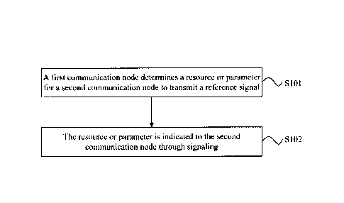
SRS is triggered based on the high-layer signaling, and a non-periodic SRS is
triggered based on
the downlink control information. In LTE-A Release 10, a manner of a non-
periodic transmission
of SRS is added, which improves the utilization rate of SRS resources to some
extent and
improves the flexibility of resource scheduling.
[0006] With the development of communication technologies, the demand for
data services
is increasing and available low-frequency carriers are in short supply.
Therefore, high-frequency
(30 GHz to 300 GHz) carrier communication which has not been fully utilized
has become an
important communication way of achieving high-speed data communication in the
future. The
high-frequency carrier communication has a large available bandwidth and can
provide effective
high-speed data communication. However, a big technical challenge for the high-
frequency
carrier communication is that high-frequency signals are attenuated
significantly in space
compared with low-frequency signals. Although this will cause spatial
attenuation losses when
the high-frequency signals are used for outdoor communication, the shorter
wavelength of the
high-frequency signals usually allows using more antennas. Therefore, the
communication is
implemented based on beams to compensate the spatial attenuation losses.
[0007] However, when the number of antennas increases, each antenna needs a
set of radio
frequency links, and digital beamforming thus brings about an increase in
costs and a loss in
power. Therefore, current studies tend to hybrid beamforming, that is, a final
beam formed by
radio frequency beams together with digital beams.
[0008] In a study of the new radio access technology (NR for short), for
the high-frequency
communication system, the eNB is configured with a large number of antennas to
form downlink
transmission beams for compensating the spatial attenuation of the high-
frequency
2
CA 03067089 2019-12-12
communication, and the UE is also configured with a large number of antennas
to form uplink
transmission beams. At this time, the SRS is also transmitted in the form of a
beam. In a future
study of the new radio access technology, the eNB may configure different
bandwidth parts
(BWP for short) for each user, and the bandwidth occupied by the BWP of a user
may be larger
than the 20 MHz bandwidth of the LTE or LTE-A system. The current SRS
bandwidth
configuration only supports 20MHz at most, which cannot meet the design
requirements of NR.
In addition, how to determine a frequency domain starting position of the SRS
and how to
achieve an antenna switching of the SRS are also problems to be solved in the
SRS design of
NR.
SUMMARY
[0009] The following is a summary of the subject matter described herein in
detail. This
summary is not intended to limit the scope of the claims.
[0010] Embodiments of the present application provide an information
transmission method
and apparatus for implementing configuration of a reference signal
transmission in a NR system.
[0011] In a first aspect, an embodiment of the present application provides
an information
transmission method, including:
[0012] determining, by a first communication node, a resource or parameter
for a second
communication node to transmit a reference signal; and
[0013] indicating the resource or parameter to the second communication
node through
signaling.
[0014] In a second aspect, an embodiment of the present application
provides an information
transmission method, including:
[0015] receiving, by a second communication node, signaling transmitted by
a first
communication node;
[0016] determining, a resource or parameter for transmitting a reference
signal based on the
signaling or based on the signaling and a rule predefined by the first
communication node and
the second communication node; and
[0017] using the resource or parameter to transmit the reference signal.
3
CA 03067089 2019-12-12
[0018] In a third aspect, an embodiment of the present application provides
an information
transmission method, including:
[0019] determining, by a first communication node, a first-level parameter
and a
second-level parameter of a reference signal resource, where the first-level
parameter includes at
least one of: the number N1 of time domain symbols continuously transmitted by
a reference
signal in a same frequency domain unit, an antenna switching switch function
Al of the
reference signal, or a frequency hopping switch function B1; and the second-
level parameter
includes at least one of: the number N2 of time domain symbols continuously
transmitted by an
antenna port group of the reference signal, an antenna switching switch
function A2 of the
reference signal in a time domain unit, or a frequency hopping switch function
B2 of the
reference signal in a time domain unit; and
[0020] receiving, by the first communication node, the reference signal
according to the
first-level parameter and the second-level parameter.
[0021] In a fourth aspect, an embodiment of the present application
provides an information
transmission method, including:
[0022] determining, by a second communication node, a first-level parameter
and a
second-level parameter of a reference signal resource, where the first-level
parameter includes at
least one of: the number N1 of time domain symbols continuously transmitted by
a reference
signal in a same frequency domain unit, an antenna switching switch function
Al of the
reference signal, or a frequency hopping switch function Bl; and the second-
level parameter
includes at least one of: the number N2 of time domain symbols continuously
transmitted by an
antenna port group of the reference signal, an antenna switching switch
function A2 of the
reference signal in a time domain unit, or a frequency hopping switch function
B2 of the
reference signal in a time domain unit; and
[0023] transmitting, by the second communication node, the reference signal
according to
the first-level parameter and the second-level parameter.
[0024] In a fifth aspect, an embodiment of the present application provides
an information
transmission apparatus, applied to a first communication node, including:
[0025] a first processing module, which is configured to determine a
resource or parameter
4
CA 03067089 2019-12-12
for a second communication node to transmit a reference signal; and
[0026] a first transmitting module, which is configured to indicate the
resource or parameter
to the second communication node through signaling.
[0027] In a sixth aspect, an embodiment of the present application provides
an information
transmission apparatus, applied to a second communication node, including:
[0028] a first receiving module, which is configured to receive signaling
transmitted by a
first communication node;
[0029] a second processing module, which is configured to determine a
resource or
parameter for transmitting a reference signal based on the signaling or based
on the signaling and
a rule predefined by the first communication node and the second processing
module; and
[0030] a second transmitting module, which is configured to use the
resource or parameter to
transmit the reference signal.
[0031] In a seventh aspect, an embodiment of the present application
provides an
information transmission apparatus, applied to a first communication node,
including:
[0032] a third processing module, which is configured to determine a first-
level parameter
and a second-level parameter of a reference signal resource, where the first-
level parameter
includes at least one of: the number NI of time domain symbols continuously
transmitted by a
reference signal in a same frequency domain unit, an antenna switching switch
function Al of
the reference signal, or a frequency hopping switch function B1; and the
second-level parameter
includes at least one of: the number N2 of time domain symbols continuously
transmitted by an
antenna port group of the reference signal, an antenna switching switch
function A2 of the
reference signal in a time domain unit, or a frequency hopping switch function
B2 of the
reference signal in a time domain unit; and
[0033] a second receiving module, which is configured to receive the
reference signal
according to the first-level parameter and the second-level parameter.
[0034] In an eighth aspect, an embodiment of the present application
provides an information
transmission apparatus, applied to a second communication node, including:
[0035] a fourth processing module, which is configured to determine a first-
level parameter
and a second-level parameter of a reference signal resource, where the first-
level parameter
CA 03067089 2019-12-12
includes at least one of: the number Ni of time domain symbols continuously
transmitted by a
reference signal in a same frequency domain unit, an antenna switching switch
function Al of
the reference signal, or a frequency hopping switch function Bl; and the
second-level parameter
includes at least one of: the number N2 of time domain symbols continuously
transmitted by an
antenna port group of the reference signal, an antenna switching switch
function A2 of the
reference signal in a time domain unit, or a frequency hopping switch function
B2 of the
reference signal in a time domain unit; and
[0036] a third transmitting module, which is configured to transmit the
reference signal
according to the first-level parameter and the second-level parameter.
[0037] In a ninth aspect, an embodiment of the present application provides
a
communication node, including: a first memory and a first processor, where the
first memory is
configured to store information transmission programs which, when executed by
the first
processor, implement the steps of the information transmission method
described in the first
aspect.
[0038] In a tenth aspect, an embodiment of the present application provides
a communication
node, including: a second memory and a second processor, where the second
memory is
configured to store information transmission programs which, when executed by
the second
processor, implement the steps of the information transmission method
described in the second
aspect.
[0039] In an eleventh aspect, an embodiment of the present application
provides a
communication node, including: a third memory and a third processor, where the
third memory
is configured to store information transmission programs which, when executed
by the third
processor, implement the steps of the information transmission method
described in the third
aspect.
[0040] In a twelfth aspect, an embodiment of the present application
provides a
communication node, including: a fourth memory and a fourth processor, where
the fourth
memory is configured to store information transmission programs which, when
executed by the
fourth processor, implement the steps of the information transmission method
described in the
fourth aspect.
6
CA 03067089 2019-12-12
[0041] In addition, an embodiment of the present application further
provides a
computer-readable medium, which is configured to store information
transmission programs
which, when executed by a processor, implement the steps of the information
transmission
method described in any one of the first to the fourth aspect.
[0042] In the embodiment of the present application, a first communication
node determines
a resource or parameter for a second communication node to transmit a
reference signal, and
indicates the resource or parameter to the second communication node through
signaling. The
second communication node receives the signaling transmitted by the first
communication node,
and determines the resource or parameter for transmitting the reference signal
based on the
signaling or based on the signaling and a rule predefined by the first
communication node and
the second communication node. In this way, design requirements for the
reference signal
transmission in the NR system are achieved.
[0043] In the embodiment of the present application, the first
communication node receives
the reference signal according to the parameters of two levels of the
reference signal resource,
and the second communication node transmits the reference signal according to
the parameters
of two levels of the reference signal resource. Through the configuration of
parameters of two
levels, the antenna switching and frequency hopping control of the reference
signal in the NR
system are achieved.
[0044] Other aspects can be understood after the drawings and detailed
description are read
and understood.
BRIEF DESCRIPTION OF DRAWINGS
[0045] FIG. 1 is a flowchart of an information transmission method
according to an
embodiment of the present application;
[0046] FIG. 2 is a flowchart of another information transmission method
according to an
embodiment of the present application;
[0047] FIG. 3 is a flowchart of another information transmission method
according to an
embodiment of the present application;
[0048] FIG. 4 is a flowchart of another information transmission method
according to an
7
CA 03067089 2019-12-12
embodiment of the present application;
[0049] FIG. 5 is a schematic diagram 1 of a multi-level bandwidth structure
corresponding to
a reference signal according to an embodiment of the present application;
[0050] FIG. 6 is a schematic diagram 2 of a multi-level bandwidth structure
corresponding to
a reference signal according to an embodiment of the present application;
[0051] FIGS. 7 (a) to 7 (f) are schematic diagrams showing frequency domain
occupancy of
PUCCHs on different time domain symbols;
[0052] FIGS. 8 (a) to 8 (j) are schematic diagrams of an example 7 of the
present application;
[0053] Fig. 9 is a schematic diagram of an information transmission
apparatus according to
an embodiment of the present application;
[0054] FIG. 10 is a schematic diagram of another information transmission
apparatus
according to an embodiment of the present application;
[0055] FIG. 11 is a schematic diagram of another information transmission
apparatus
according to an embodiment of the present application;
[0056] FIG. 12 is a schematic diagram of another information transmission
apparatus
according to an embodiment of the present application;
[0057] FIG. 13 is a schematic diagram of a communication node according to
an
embodiment of the present application; and
[0058] FIG. 14 is a schematic diagram of another communication node
according to an
embodiment of the present application.
DETAILED DESCRIPTION
[0059] Embodiments of the present application will be described in detail
in conjunction
with the drawings, and it should be understood that the embodiments described
hereinafter are
intended to describe and explain the present application and not to limit the
present application.
[0060] The steps illustrated in the flowcharts of the drawings may be
executed by, for
example, a set of computer-executable instructions in a computer system.
Although the
flowcharts illustrate a logical order of execution, the steps illustrated or
described may, in some
cases, be executed in a different order from the one illustrated or described
herein.
8
CA 03067089 2019-12-12
[0061] FIG. 1 is a flowchart of an information transmission method
according to an
embodiment of the present application. As illustrated in FIG. 1, the
information transmission
method in the embodiment may include the steps described below.
[0062] In S101, a first communication node determines a resource or
parameter for a second
communication node to transmit a reference signal.
[0063] In S102, the resource or parameter is indicated to the second
communication node
through signaling.
[0064] In the embodiment, the first communication node refers to a node
configured to
determine a transmission mode of the second communication node and to perform
signaling
indication to the second communication node, and the second communication node
refers to a
node configured to receive the signaling. In an implementation mode, the first
communication
node may be nodes such as a base station of a macro cell, a base station or
transmission node of a
small cell, a sending node in a high-frequency communication system, or a
sending node in an
Internet of Things system, and the second communication node may be nodes in a
communication system such as a UE, a mobile phone, a portable device, or a
car. In another
implementation mode, the base station of a macro cell, the base station or
transmission node of a
small cell, the sending node in a high-frequency communication system, the
sending node in an
Internet of Things system, or the like may serve as the second communication
node, and the UE
may serve as the first communication node.
[0065] In the embodiment, the signaling may include at least one of: radio
resource control
(RRC) signaling, media access control control element (MAC CE) signaling,
physical downlink
control signaling, or physical layer dynamic control signaling.
[0066] In the embodiment, the reference signal includes one of: a SRS, an
uplink
demodulation reference signal, a downlink demodulation reference signal, a
downlink channel
state information reference signal (CSI-RS), an uplink phase tracking
reference signal (PTRS),
and a downlink PTRS.
UL
[0067] In the embodiment, BWP is the
bandwidth value of the bandwidth part. BWP
DL
refers to an uplink bandwidth part, and B" refers to
a downlink bandwidth part.
9
CA 03067089 2019-12-12
[0068] In an exemplary implementation mode, the resource or parameter at
least includes
one or more of: a frequency domain starting position, a frequency domain end
position, a
transmission bandwidth, a number of segments, a bandwidth configuration index,
a bandwidth
parameter, a parameter indicating whether a resource is repeated or the same,
an antenna port
number or index, a calculation manner of a frequency domain starting position
of a maximum
bandwidth of the reference signal in a multi-level bandwidth structure, a
parameter related to
obtaining the frequency domain starting position of the maximum bandwidth of
the reference
signal in the multi-level bandwidth structure, or information of the multi-
level bandwidth
structure containing the reference signal.
[0069] 1 ,
In the embodiment, the number of segments has the same meaning as NO N N2
N3 in the bandwidth configuration table 4a in LTE, or the number of segments
may be defined
as a ratio of a transmission bandwidth of a previous level to a transmission
bandwidth of a
current level in the tree structure bandwidth configuration of the reference
signal.
[0070] In the embodiment, the reference signal may be transmitted in at
least one of the
following manners: a transmission beam, a transmission antenna, a transmission
sector, a
transmitting end precoding, an antenna port indication, an antenna weight
vector indication, an
antenna weight matrix indication, a space-division multiplexing mode, a
frequency domain/time
domain transmission diversity mode, a transmission sequence, the number of
transmission layers,
a transmission model, a modulation and coding mode, or a reference signal
indication.
[0071] In the embodiment, the reference signal may be received in at least
one of the
following manners: a receiving beam; a receiving antenna; a receiving antenna
panel; a receiving
sector; a first beam resource corresponding manner, where the first beam
resource is a beam
resource, of the first communication node, indicated in a Quasi-Co-Location
(QCL) of both the
reference signal and an antenna port; or a second beam resource corresponding
manner, where
the second beam resource is a beam resource, of the first communication node,
indicated in a
QCL of both a base reference signal and the antenna port.
[0072] In an exemplary implementation mode, the step in which a first
communication node
determines a resource or parameter for a second communication node to transmit
a reference
CA 03067089 2019-12-12
signal may include that: the first communication node determines the resource
or parameter for
the second communication node to transmit the reference signal based on a rule
predefined by
the first communication node and the second communication node.
[0073] In an exemplary implementation mode, the step in which a first
communication node
determines a resource or parameter for a second communication node to transmit
a reference
signal includes at least one of the steps described below.
[0074] The first communication node determines a bandwidth configuration
index actually
used by the second communication node according to at least one of a bandwidth
value or the
bandwidth configuration index of a bandwidth part configured for the second
communication
node.
[0075] The first communication node determines a transmission bandwidth set
of the
reference signal according to the bandwidth configuration index of the
reference signal.
[0076] The first communication node determines the transmission bandwidth
or the number
of segments of the reference signal according to at least one of the bandwidth
value, the
bandwidth configuration index or the bandwidth parameter of the bandwidth part
configured for
the second communication node.
[0077] In an exemplary implementation mode, the step in which the first
communication
node determines a bandwidth configuration index actually used by the second
communication
node according to at least one of a bandwidth value or the bandwidth
configuration index of a
bandwidth part configured for the second communication node includes the step
described
below.
[0078] Determining the bandwidth configuration index actually used by the
second
communication node includes at least one of:
4 x [1--11---"N ] - C
4 SRS
[0079] (1) ;
8 - C SRS
[0080] (2) ;
[0081] (3) ;
11
CA 03067089 2019-12-12
16x HN16i - CSRS
[0082] (4) ; or
[0083] (5) when a maximum transmission bandwidth of the reference signal
corresponding
4 x [ N r-i 8 x [ IsvP j
to the bandwidth configuration index is less than or equal to or or
12 x [ "*" or ] 16x[16 N -vi'-1, selecting a maximum bandwidth
configuration index and
subtracting the maximum bandwidth configuration index by C s"s to obtain as
the bandwidth
configuration index actually used by the second communication node.
[0084] L i is a round-down function, NB is
the bandwidth value of the bandwidth part,
C
SRS is the bandwidth configuration index, and the first communication node
configures
N
CSRS and B" for the second communication node through the signaling.
[0085] In an exemplary implementation mode, the step in which the first
communication
node determines a transmission bandwidth set of the reference signal according
to the bandwidth
configuration index of the reference signal includes the step described below.
[0086] When the bandwidth configuration index of the reference signal is
greater than or
equal to 17, or the bandwidth configuration index of the reference signal is
less than or equal to
14, or the bandwidth configuration index of the reference signal is an integer
included in a range
from 0 to 31 or from 0 to 63, determining the transmission bandwidth set
includes at least one of:
[0087] (1) 108, 36, 12,4;
[0088] (2) 112, 56, 28, 4;
[0089] (3) 112, 56, 8, 4;
[0090] (4) 120, 60, 20, 4;
[0091] (5) 120, 40, 20, 4;
[0092] (6) 128, 64, 32, 4;
[0093] (7) 128, 32, 16, 4;
[0094] (8) 128, 32, 8, 4;
12
CA 03067089 2019-12-12
[0095] (9) 136, 68, 4, 4;
[0096] (10) 144, 72, 24, 4;
[0097] (11) 144, 72, 36, 4;
[0098] (12) 144, 72, 12, 4;
[0099] (13) 144, 48, 24, 4;
[0100] (14) 144, 48, 12,4;
[0101] (15) 144, 48, 16,4;
[0102] (16) 144, 48, 8, 4;
[0103] (17) 160, 80, 40, 4;
[0104] (18) 160, 80, 20,4;
[0105] (19) 160, 40, 20, 4;
[0106] (20) 160, 40, 8,4;
[0107] (21) 168, 84, 28, 4;
[0108] (22) 176, 88, 44, 4;
[0109] (23) 180, 60, 20, 4;
[0110] (24) 192, 96, 32, 4;
[0111] (25) 192, 96, 48, 4;
[0112] (26) 192, 48, 24, 4;
[0113] (27) 192, 48, 16, 4;
[0114] (28) 192, 48, 12, 4;
[0115] (29) 200, 100, 20, 4;
[01161 (30) 200, 40, 20, 4;
[0117] (31) 200, 40, 8, 4;
[0118] (32) 208, 104, 52, 4;
[0119] (33) 216, 108, 36, 4;
[0120] (34) 240, 120, 60, 4;
[0121] (35) 240, 120, 40, 4;
[0122] (36) 240, 120, 20, 4;
[0123] (37) 240, 80, 40, 4;
13
CA 03067089 2019-12-12
[0124] (38) 240, 80, 20, 4;
[0125] (39) 240, 80, 8, 4;
[0126] (40) 256, 128, 64, 4;
[0127] (41) 256, 64, 32, 4;
[0128] (42) 256, 64, 16, 4;
[0129] (43) 256, 64, 8, 4; or
[0130] (44) 272, 136, 68, 4.
[0131] In an exemplary implementation mode, the step in which the first
communication
node determines the transmission bandwidth or the number of segments of the
reference signal
according to at least one of the bandwidth value, the bandwidth configuration
index or the
bandwidth parameter of the bandwidth part configured for the second
communication node is
performed in at least one of the following manners, or a transmission
bandwidth set
corresponding to one or more bandwidth configuration indexes satisfies one of
the following
relationships:
[0132] Manner 1:
lc; = floor ((A Tmvp-4xCsks, )/ 4 )
Let 2'
then the transmission bandwidth is:
MSRS,0 =4 x ko .
= 4 x A I , if (( Bwp ¨4 x Csns ) / 4) mod 2' = 0 and k, E
Even
MSRS,i+1
4 , otherwise
=
[0133] Manner 2:
k, = floor ((ls1 imp +4xCsns )I4)
Let 2'
then the transmission bandwidth is:
MSRS,0¨ 4 x k .
14
CA 03067089 2019-12-12
4 x ki,õ if ((I/imp + 4 x Csõs) / 4) mod 2' = 0 and ki E Even
MSRS,i+I =
4 otherwise .
[0134] Manner 3:
The number of segments is:
N0 =1.
2 , if ((NB" ¨4 x C)/ 4) mod 2' = 0 and lc; E Even
Ni+, = ki , if ((N Bõ ¨4 x CsRs)/ 4) mod 2' = 0 and ki E Odd
{
1 , otherwise
=
[0135] Manner 4:
M . = 4x floor( __________
SRS ,1 (N Bwp-4xCsRs )/ 4 )
21 x3./ x51
The transmission bandwidth is ; or
lc, = 4 x floor( ( NB w2p, +4x3' C:i=Rs ) / 4 )
=
[0136] Manner 5:
{16xL(Nmvp ¨16xCsms)/16_1 /2' , if i<3
¨
MSRS i ¨
= 4
The transmission bandwidth is , otherwise
; or
= {16xL(Nõwp+16Cs
x,$)/16] /2'
MSRS,i
4 , otherwise.
101371 Manner 6:
{
MSRS i ¨
16 x LO /Imp ¨16xCsRs)/16 i Idõ if i<3
¨
' 4
The transmission bandwidth is , otherwise
; or
164(NRwp+16xCsRs)/16i id, msRsl={, if i<3
MSRS,i =
4 , otherwise.
i .; i c I i
,
' IS
d. ' 2' x 3 x 5 , or s one or more integers in a range from 1 to 17,
including 1 and 17,
CA 03067089 2019-12-12
values of i, j and 1 are non-negative integers, MSRS'i is the transmission
bandwidth of the
B
reference signal, floor() is a round-down function, L -I is a round-down
function, =SRS
BSRS is the bandwidth parameter of the reference signal, B" is the
bandwidth value of the
bandwidth part, and the first communication node configures SRS and BWP
for the second
communication node through the signaling.
[0138] In an exemplary implementation mode, indicating the resource or
parameter for the
second communication node through signaling includes the step described below.
[0139] An offset value of a frequency domain starting position
corresponding to a maximum
bandwidth in a multi-level bandwidth structure containing the reference signal
relative to a first
frequency domain starting position is indicated to the second communication
node through the
signaling, where the first frequency domain starting position is obtained by
the second
communication node based on a rule predefined by the first communication node
and the second
communication node.
[0140] In an exemplary implementation mode, the calculation manner of a
frequency domain
starting position of a maximum bandwidth of the reference signal in a multi-
level bandwidth
structure includes at least one of:
[0141] (1) 1c- (P)=-(LNuL / 2_1¨m /2 ¨ AP'
RB SRS,0 ATRB zr(p)
offiel iv Sc -I- mTC
, where the first frequency domain
k-(p) .([NRUBL _
2 MsRs,o /2) NsRBc kr(C)
starting position is:
Tc(p) (NRuBL _ ¨ A (I '7õ Nsili3 (P)
[0142] (2) smR7, 0 c k
TC , where the first frequency domain starting
position is:
p) = (N Rust. _ msmRazo)N s1:13 ;
I t or
A 7sBe,NRB
[0143] (3) , where the first frequency domain starting
position is:
16
CA 03067089 2019-12-12
k(P) = krciv
A PRB
[0144] ('fbei is the offset value of the frequency domain start position
corresponding to the
maximum bandwidth in the multi-level bandwidth structure containing the
reference signal
NRB ATUL
relative to the first frequency domain start position and is an integer in
units of SC , RB
represents the bandwidth part, 1SRS,0 is length information of a frequency
domain bandwidth
k(P)
corresponding to the maximum bandwidth in the multi-level bandwidth structure,
TC
RB
represents an offset quantity of the maximum bandwidth within a unit N sc F is
a port index,
and inisnR7' is length information of a maximum bandwidth in one or more
multi-level
bandwidth structures.
[0145] In an exemplary implementation mode, the calculation manner of a
frequency domain
starting position of a maximum bandwidth of the reference signal in a multi-
level bandwidth
structure includes one of:
\ 1-(14'3 ¨ K
[0146] ( k TC ;
TC* M 118"4 N aa KC .
[0147] (2) 0 - 2 SRS,b - 13' ma 2 SC TC =
VP) = (Nfyi _ msRs, resits N )Nfts K.
[0148] (3) 0 b b SC TC
[0149] (4) (1') = OATRuBL msizs,0/2 APRBi ' 12B + kAp)
offieSC "TC
9
17(p) = ( RNuBL _ MSmRaxS,0 ) cNsRB
[0150] (5) -0 IC
[0151] (6) (P) = ([NuL / 2] - mSRS 0 /2)N" + kTC(P)
RB SC
pp) = (NRuB sRs
L _ mmax,0 ,
_ A,PffRBsei )N _I_ k(p)
[0152] (7) -0 TC ; or
17
CA 03067089 2019-12-12
pP) k,(p) A PRB RB
[0153] (8) -IC `-'offset Sc =
9
APRB NRB UL
[0154] ffiel is an offset value and an integer in units of SC , RB
represents the
bandwidth part, rnSRS,0 is length information of a frequency domain bandwidth
corresponding to
/,(p)
the maximum bandwidth in the multi-level bandwidth structure, 'lc represents
an offset
RB B,
quantity of the maximum bandwidth within a unit N sc , is a
port index, and 85 is level
information of a bandwidth, in the multi-level bandwidth structure, of the
reference signal on one
frequency domain symbol; and NV is the number of bandwidths, of a b. th level,
included in one
m max
bandwidth of a (V-1)th level, and SRS,0 is length information of a maximum
bandwidth in one
or more multi-level bandwidth structures.
[0155] In an exemplary implementation mode, one bandwidth of bandwidths of
a bth level in
the multi-level structure containing the reference signal includes one or more
bandwidths of a
(b+l)th level, where b is a non-negative integer.
[0156] In an exemplary implementation mode, the parameter or a
configuration range of the
parameter is obtained according to position information of a time domain
symbol in one time
unit; or a reference signal resource is located on different time domain
symbols in one time unit,
and the parameter or the configuration range of the parameter is different.
[0157] In an exemplary implementation mode, the antenna port number or
index remains
unchanged on M consecutive time domain symbols, where M is an integer greater
than 0.
[0158] In an exemplary implementation mode, when a plurality of resources
are indicated
through the signaling, configuration values or parameter values of the
plurality of resources are
the same on L consecutive time domain symbols, or configuration values or
parameter values of
the plurality of resources are different on L consecutive time domain symbols,
where L is an
integer greater than 0.
[0159] In an exemplary implementation mode, when a plurality of resources
are indicated
through the signaling, the plurality of resources constitute a resource set or
a resource group, and
18
CA 03067089 2019-12-12
a parameter of the resource set or the resource group is configured to
indicate whether the
plurality of resources in the resource set or the resource group are the same
or repeated.
[0160] In an exemplary implementation mode, when the parameter indicating
whether a
resource is repeated or the same has a value of 1 or the state is on, the
parameter indicating
whether a resource is repeated or the same indicates that all parameter
configuration values of a
plurality of SRS resources in a resource set or a resource group are the same,
or that parameter
values used for representing transmission beams or antenna ports or frequency
domain resources
in the plurality of SRS resources are the same, or that the plurality of SRS
resources use a same
transmission beam or antenna port or frequency domain resource.
[0161] In an exemplary implementation mode, a plurality of the resources
are configured to
implement at least one function of a group consisting of:
[0162] switching of antennas or transmission ports of a reference signal;
[0163] transmitting of a reference signal on a plurality of time domain
resources in a same
transmission manner or at a same frequency domain position; and
[0164] reception on the first communication node of a reference signal
transmitted from the
second communication node on a plurality of time domain resources in a same
receiving manner.
[0165] In an exemplary implementation mode, the number of segments N N ,
where <=
represents less than or equal to; and i <j.
[0166] FIG. 2 is a flowchart of an information transmission method
according to an
embodiment of the present application. As illustrated in FIG. 2, the
information transmission
method in the embodiment may include the steps described below.
[0167] In S201, a second communication node receives signaling transmitted
by a first
communication node.
[0168] In S202, a resource or parameter for transmitting a reference signal
is determined
based on the signaling or based on the signaling and a rule predefined by the
first communication
node and the second communication node.
[0169] In S203, the resource or parameter is used to transmit the reference
signal.
[0170] In the embodiment, the first communication node refers to a node
configured to
determine a transmission mode of the second communication node and to perform
signaling
19
CA 03067089 2019-12-12
indication to the second communication node, and the second communication node
refers to a
node configured to receive the signaling. In an implementation mode, the first
communication
node may be nodes such as a base station of a macro cell, a base station or
transmission node of a
small cell, a sending node in a high-frequency communication system, or a
sending node in an
Internet of Things system, and the second communication node may be nodes in a
communication system such as a UE, a mobile phone, a portable device, or a
car. In another
implementation mode, the base station of a macro cell, the base station or
transmission node of a
small cell, the sending node in a high-frequency communication system, the
sending node in an
Internet of Things system, or the like may serve as the second communication
node, and the UE
may serve as the first communication node.
[0171] In the embodiment, the signaling may include at least one of: RRC
signaling, MAC
CE signaling, physical downlink control signaling, or physical layer dynamic
control signaling.
[0172] In the embodiment, the reference signal includes one of: a SRS, an
uplink
demodulation reference signal, a downlink demodulation reference signal, a CSI-
RS, an uplink
PTRS, and a downlink PTRS.
101731 In an exemplary implementation mode, the resource or parameter
includes at least
one of: a frequency domain starting position, a frequency domain end position,
a transmission
bandwidth, a number of segments, a bandwidth configuration index, a bandwidth
parameter, a
parameter configured to indicate whether a resource is repeated or the same,
an antenna port
number or index, a calculation manner of a frequency domain starting position
of a maximum
bandwidth of the reference signal in a multi-level bandwidth structure, a
parameter related to
obtaining the frequency domain starting position of the maximum bandwidth of
the reference
signal in the multi-level bandwidth structure, or information of the multi-
level bandwidth
structure containing the reference signal.
[0174] In an exemplary implementation mode, determining a resource or
parameter for
transmitting a reference signal based on the signaling or based on the
signaling and a rule
predefined by the first communication node and the second communication node
includes at
least one of the steps described below.
[0175] The second communication node determines a bandwidth configuration
index
CA 03067089 2019-12-12
actually used by the second communication node based on at least one of a
bandwidth value or
the bandwidth configuration index of a bandwidth part (BWP) configured by the
signaling for
the second communication node and the rule predefined by the first
communication node and the
second communication node.
[0176] The second communication node determines a transmission bandwidth
set of the
reference signal based on the bandwidth configuration index of the reference
signal and the rule
predefined by the first communication node and the second communication node.
[0177] The second communication node determines the transmission bandwidth
or the
number of segments of the reference signal based on at least one of the
bandwidth value, the
bandwidth configuration index or the bandwidth parameter of the bandwidth part
configured by
the signaling for the second communication node and the rule predefined by the
first
communication node and the second communication node.
[0178] In an exemplary implementation mode, the step in which the second
communication
node determines a bandwidth configuration index actually used by the second
communication
node based on at least one of a bandwidth value or the bandwidth configuration
index of a
bandwidth part configured by the signaling for the second communication node
and the rule
predefined by the first communication node and the second communication node
includes the
step described below.
[0179] Determining the bandwidth configuration index actually used by the
second
communication node includes at least one of:
4 x [ SRS - C
[0180] (1)
8 x [ N 8 Bwp
- µ-' SRS
[0181] (2)
1 2 x [ v PN - C
SRS
[0182] (3)
16 µ-"SRS
[0183] (4) ; or
[0184] (5) when a maximum transmission bandwidth of the reference signal
corresponding
4 x 8 x
to the bandwidth configuration index is less than or equal to or L 8
or
21
CA 03067089 2019-12-12
12 x 16 x [ N`67"'
or , selecting a maximum bandwidth configuration index and
subtracting the maximum bandwidth configuration index by C SI6 to obtain as
the bandwidth
configuration index actually used by the second communication node.
[0185] L -is a round-down function, B" is the
bandwidth value of the bandwidth part,
SRS is the bandwidth configuration index, and the first communication node
configures
SRS and B" for the second communication node through the signaling.
[0186] In an exemplary implementation mode, the step in which the second
communication
node determines a transmission bandwidth set of the reference signal based on
the bandwidth
configuration index of the reference signal and the rule predefined by the
first communication
node and the second communication node includes the step described below.
[0187] When the bandwidth configuration index of the reference signal is
greater than or
equal to 17, or the bandwidth configuration index of the reference signal is
less than or equal to
14, or the bandwidth configuration index of the reference signal is an integer
comprised in a
range from 0 to 31 or from 0 to 63, indicating the transmission bandwidth set
includes at least
one of:
[0188] (1) 108, 36, 12, 4;
[0189] (2) 112, 56, 28, 4;
[0190] (3) 112, 56, 8, 4;
[0191] (4) 120, 60, 20, 4;
[0192] (5) 120, 40, 20, 4;
[0193] (6) 128, 64, 32, 4;
[0194] (7) 128, 32, 16, 4;
[0195] (8) 128, 32, 8, 4;
[0196] (9) 136, 68, 4, 4;
[0197] (10) 144, 72, 24, 4;
[0198] (11) 144, 72, 36, 4;
22
CA 03067089 2019-12-12
[0199] (12) 144, 72, 12, 4;
[0200] (13) 144, 48, 24, 4;
[0201] (14) 144, 48, 12, 4;
[0202] (15) 144, 48, 16, 4;
[0203] (16) 144, 48, 8, 4;
[0204] (17) 160, 80, 40, 4;
[0205] (18) 160, 80, 20, 4;
[0206] (19) 160, 40, 20, 4;
[0207] (20) 160, 40, 8, 4;
[0208] (21) 168, 84, 28, 4;
[0209] (22) 176, 88, 44, 4;
[0210] (23) 180, 60, 20, 4;
[0211] (24) 192, 96, 32, 4;
[0212] (25) 192, 96, 48, 4;
[0213] (26) 192, 48, 24, 4;
[0214] (27) 192, 48, 16, 4;
[0215] (28) 192, 48, 12, 4;
[0216] (29) 200, 100, 20, 4;
[0217] (30) 200, 40, 20, 4;
[0218] (31) 200, 40, 8, 4;
[0219] (32) 208, 104, 52, 4;
[0220] (33) 216, 108, 36, 4;
[0221] (34) 240, 120, 60, 4;
[0222] (35) 240, 120, 40, 4;
[0223] (36) 240, 120, 20, 4;
[0224] (37) 240, 80, 40, 4;
[0225] (38) 240, 80, 20, 4;
[0226] (39) 240, 80, 8, 4;
[0227] (40) 256, 128, 64, 4;
23
CA 03067089 2019-12-12
[0228] (41) 256, 64, 32, 4;
[0229] (42) 256, 64, 16, 4;
[0230] (43) 256, 64, 8, 4; or
[0231] (44) 272, 136, 68, 4.
[0232] In an exemplary implementation mode, the step in which the second
communication
node determines the transmission bandwidth or the number of segments of the
reference signal
based on at least one of the bandwidth value, the bandwidth configuration
index or the
bandwidth parameter of the bandwidth part configured by the signaling for the
second
communication node and the rule predefined by the first communication node and
the second
communication node is performed in one of the following manners:
[0233] Manner 1:
= floor(NB"-4xCws, )/ 4 )
Let 2'
then the transmission bandwidth is:
-- 4 x ko
MSRS, 0
54x k,,, , if ((N,1, ¨ 4 x Csõs )/ 4) mod 2 = 0 and k, e Even
MSRS,1+1
4 , otherwise
=
[0234] Manner 2:
ki = floor(NB"+4xC,16)/4)
Let 2'
then the transmission bandwidth is:
¨ MSRS, 0 -4 x ko
- 4 x k,+i , if (Km, + 4 x CsRs)/ 4) mod 2' = 0 and k, E Even
m
SRS,i+1
4 , otherwise
=
[0235] Manner 3:
The number of segments is:
No =1
24
CA 03067089 2019-12-12
2 , if ((Nõi, ¨4 x Csks,) /4) mod 2' = 0 and k, E Even
N,,,= k if ((NBwp ¨4 X CsRs ) / 4)mod 2' = 0 and k, E Odd
{
1 , otherwise
[0236] Manner 4:
16xL(Nmn,-16xCsRs)/16 i /2' , if i<3
nISRS,/ =
4 otherwise
The transmission bandwidth is ,
; or
m = 16xL(Nmvp +16xCsRs)/16j /2' , if
i<3
SAS,/
4 , otherwise
=
[0237] Manner 6:
m
16 x L(NBwi, ¨16 x CsR, ) /16 i Id, , if i < 3
¨
S
RSJ ¨ {4 otherwise
The transmission bandwidth is ,
; or
16xL(NBwp+16xCsRs)/16 m _I /d, , if i<3
¨
SRS ,i . ¨ {4 , otherwise
=
cl, is 21 x3' x51 ,or d, is one or more integers in a range from Ito 17,
including land 17,
values of i, j and I are non-negative integers, /NM,/ is the transmission
bandwidth of the
reference signal, floor() is a round-down function, L -I is a round-down
function, i = BSRS ,
BSRS is the bandwidth parameter of the reference signal, N BWP is the
bandwidth value of the
B N
bandwidth part, and the first communication node configures SRS and B"
for the second
communication node through the signaling.
[0238] In an exemplary implementation mode, determining a resource or
parameter for
transmitting a reference signal based on the signaling or based on the
signaling and a rule
predefined by the first communication node and the second communication node
includes the
steps described below.
CA 03067089 2019-12-12
[0239] An offset value of a frequency domain starting position
corresponding to a maximum
bandwidth in a multi-level bandwidth structure containing the reference signal
relative to a first
frequency domain starting position is obtained through the signaling or the
agreed rule, where
the first frequency domain starting position is obtained by the second
communication node based
on the rule predefined by the first communication node and the second
communication node.
[0240] In an exemplary implementation mode, the calculation manner of a
frequency domain
starting position of a maximum bandwidth of the reference signal in a multi-
level bandwidth
structure includes at least one of:
pp) = v UL
0 ¨ RB ' SRS,0 /2 ¨ ATRB kv(p)
offser SC ' "TC
[0241] (1) ,where the first frequency domain
=([N MSRS,0 /2) NSRCB kT(11)
starting position is:
[0242] (2) kP) = (NRuBL mm
SRa x S , 0 AlR
off',B B
ei)N:kT( cP) , where the first frequency domain starting
position is:
[0243] 1-ZI(P) = (NRuBL mm B SRa xS , 0 )N:k (rPC ; or
pp) = k(p) j_ A PRB v RB
[0244] (3) IC ' '"offseI Sc , where the first frequency domain
starting position is:
=
TI(p) ,r(p)
C .
APR8
[0245] ffiet is the offset value of the frequency domain start position
corresponding to the
maximum bandwidth in the multi-level bandwidth structure containing the
reference signal
RB UL
relative to the first frequency domain start position and is an integer in
units of N sc RB
represents the bandwidth part, 1SRS,0 is length information of a frequency
domain bandwidth
k(P)
corresponding to the maximum bandwidth in the multi-level bandwidth structure,
TC
NB
represents an offset quantity of the maximum bandwidth within a unit c
is a port index,
26
CA 03067089 2019-12-12
nand mskax
s. is length information of a maximum bandwidth in one or more multi-level
bandwidth structures.
[0246] In an exemplary implementation mode, the calculation manner of a
frequency domain
starting position of a maximum bandwidth of the reference signal in a multi-
level bandwidth
structure includes one of:
[0247] (1)
TC'P = NA ¨ B N f) N+ K
MSRS,b ribcs:so 4-1-2
10248] (2) (I 2 ,
_ NI ut, ssRs ) " CP)
[0249] (3) ko - (--- -
Kg 1115RS,b 1 n L 7,1b'...0 ''V.- N+ K
SC TC ;
Tc (p) = (L. NuL /2] _ m /2 _ A " PRB ) NRB + k(p)
[0250] (4) RB 1 SRS 0 , offier SC TC .
ic-(p) = (N UL _ nismg 0)N:B + k(rp) .
[0251] (5) 0 C ,
Tc(p) = ([NUL 1 2]- m
RS
0 RB S,0 /2)NSRCB +14PC)
[0252] (6) ;
pp) = (N uBL, _ õõ
[0253] (7) ,-0 R -sinRa's`,0 - A.PffRfei )NscB + ki-
'c 7--) .
, or
Tc(p) _ y(p) _i_ A PRB AT RB
0
[0254] (8) "Iv - -offie, Ivso.
A PI213 NRB ATUL
[0255] -`offiei is an offset value and an integer in units of sc , ' v
RB represents the
bandwidth part, in5R5,0 is length information of a frequency domain bandwidth
corresponding to
k(p)
the maximum bandwidth in the multi-level bandwidth structure, -"it represents
an offset
RB ,, i quantity of the maximum
bandwidth within a unit N sc , P s a port index, and BsRs is level
information of a bandwidth, in the multi-level bandwidth structure, of the
reference signal on one
frequency domain symbol; and NI). is the number of bandwidths of a b' level
included in one
max
bandwidth of the (b`-1) level, and msRasx, is length information of a maximum
bandwidth in one
27
CA 03067089 2019-12-12
or more multi-level bandwidth structures.
[0256] In an exemplary implementation mode, one bandwidth of bandwidths of
a bth level in
the multi-level structure containing the reference signal includes one or more
bandwidths of a
(b+l)th level, where b is a non-negative integer.
[0257] In an exemplary implementation mode, the parameter or a
configuration range of the
parameter is obtained according to position information of a time domain
symbol in one time
unit; or a reference signal resource is located on different time domain
symbols in one time unit,
and the parameter or the configuration range of the parameter is different.
[0258] In an exemplary implementation mode, the antenna port number or
index remains
unchanged on M consecutive time domain symbols, where M is an integer greater
than 0.
[0259] In an exemplary implementation mode, when a plurality of resources
for transmitting
the reference signal are included, configuration values or parameter values of
the plurality of
resources are the same on L consecutive time domain symbols, or configuration
values or
parameter values of the plurality of resources are different on L consecutive
time domain
symbols, where L is an integer greater than 0.
[0260] In an exemplary implementation mode, when a plurality of resources
for transmitting
the reference signal are included, the plurality of resources constitute a
resource set or a resource
group, and a parameter of the resource set or the resource group is configured
to indicate whether
the plurality of resources in the resource set or the resource group are the
same or repeated.
[0261] In an exemplary implementation mode, when the parameter indicating
whether a
resource is repeated or the same has a value of 1 or the state is on, the
parameter indicating
whether a resource is repeated or the same indicates that all parameter
configuration values of a
plurality of SRS resources in a resource set or a resource group are the same,
or that parameter
values used for representing transmission beams or antenna ports or frequency
domain resources
in the plurality of SRS resources are the same, or that the plurality of SRS
resources use a same
transmission beam or antenna port or frequency domain resource.
[0262] FIG. 3 is a flowchart of an information transmission method
according to an
embodiment of the present application. As illustrated in FIG. 3, the
information transmission
method in the embodiment may include the steps described below.
28
CA 03067089 2019-12-12
[0263] In S301, a first communication node determines a first-level
parameter and a
second-level parameter of a reference signal resource, where the first-level
parameter includes at
least one of: the number NI of time domain symbols continuously transmitted by
a reference
signal in a same frequency domain unit, an antenna switching switch function
Al of the
reference signal, or a frequency hopping switch function Bl; and the second-
level parameter
includes at least one of: the number N2 of time domain symbols continuously
transmitted by an
antenna port group of the reference signal, an antenna switching switch
function A2 of the
reference signal in a time domain unit, or a frequency hopping switch function
B2 of the
reference signal in a time domain unit.
[0264] In S302, the first communication node receives the reference signal
according to the
first-level parameter and the second-level parameter.
[0265] The antenna ports in one antenna port group are simultaneously
transmitted.
[0266] In an exemplary implementation mode, the step in which the first
communication
node receives the reference signal according to the first-level parameter and
the second-level
parameter includes the step described below.
[0267] For the reference signal, N1 time domain symbols are first
repeatedly received in a
frequency domain unit, and then N1 time domain symbols are repeatedly received
in another
frequency domain unit that is hopped into.
[0268] In an exemplary implementation mode, the step in which the first
communication
node receives the reference signal according to the first-level parameter and
the second-level
parameter includes the step described below.
[0269] When a plurality of port groups are provided, one port group is
first used to
repeatedly receive N2 time domain symbols and then another port group is used
to repeatedly
receive N2 time domain symbols.
[0270] In an exemplary implementation mode, N2 is less than NI.
[0271] In an exemplary implementation mode, on the NI time domain symbols
of one
frequency domain unit, different antenna port groups are time-division
multiplexed, and each
antenna port group continuously receives N2 time domain symbols.
[0272] In an exemplary implementation mode, the method further includes the
step described
29
CA 03067089 2019-12-12
below.
[0273] The first communication node indicates the first-level parameter and
the second-level
parameter of the reference signal resource to a second communication node
through signaling.
[0274] In an exemplary implementation mode, the number of time domain
symbols
configured in the reference signal resource is N, Ni is less than or equal to
N, and N2 is less than
or equal to N.
[0275] In an implementation mode of the embodiment, the first communication
node may be
nodes such as a base station of a macro cell, a base station or transmission
node of a small cell, a
sending node in a high-frequency communication system, or a sending node in an
Internet of
Things system, and the second communication node may be nodes in a
communication system
such as a UE, a mobile phone, a portable device, or a car. In another
implementation mode, the
base station of a macro cell, the base station or transmission node of a small
cell, the sending
node in a high-frequency communication system, the sending node in an Internet
of Things
system, or the like may serve as the second communication node, and the UE may
serve as the
first communication node.
[0276] FIG. 4 is a flowchart of an information transmission method
according to an
embodiment of the present application. As illustrated in FIG. 4, the
information transmission
method in the embodiment may include the steps described below.
102771 In S401, a second communication node determines a first-level
parameter and a
second-level parameter of a reference signal resource, where the first-level
parameter includes at
least one of: the number Ni of time domain symbols continuously transmitted by
a reference
signal in a same frequency domain unit, an antenna switching switch function
Al of the
reference signal, or a frequency hopping switch function Bl; and the second-
level parameter
includes at least one of: the number N2 of time domain symbols continuously
transmitted by an
antenna port group of the reference signal, an antenna switching switch
function A2 of the
reference signal in a time domain unit, or a frequency hopping switch function
B2 of the
reference signal in a time domain unit.
[0278] In S402, the second communication node transmits the reference
signal according to
the first-level parameter and the second-level parameter.
CA 03067089 2019-12-12
[0279] The antenna ports in one antenna port group are simultaneously
transmitted.
[0280] In an exemplary implementation mode, the step in which the second
communication
node transmits the reference signal according to the first-level parameter and
the second-level
parameter includes the step described below.
[0281] For the reference signal, Ni time domain symbols are first
repeatedly transmitted in a
frequency domain unit, and then Ni time domain symbols are repeatedly
transmitted in another
frequency domain unit that is hopped into.
[0282] In an exemplary implementation mode, the step in which the second
communication
node transmits the reference signal according to the first-level parameter and
the second-level
parameter includes the step described below.
[0283] When a plurality of port groups are provided, one port group is
first used to
repeatedly transmit N2 time domain symbols and then another port group is used
to repeatedly
transmit N2 time domain symbols.
[0284] In an exemplary implementation mode, N2 is less than NI.
[0285] In an exemplary implementation mode, on the Ni time domain symbols
of one
frequency domain unit, different antenna port groups are time-division
multiplexed, and each
antenna port group continuously transmits N2 time domain symbols.
[0286] In an exemplary implementation mode, the method further includes the
step described
below.
[0287] The second communication node receives signaling through which a
first
communication node indicates the first-level parameter and the second-level
parameter of the
reference signal resource.
[0288] In an exemplary implementation mode, the number of time domain
symbols
configured in the reference signal resource is N, Ni is less than or equal to
N, and N2 is less than
or equal to N.
[0289] In an implementation mode of the embodiment, the first communication
node may be
nodes such as a base station of a macro cell, a base station or transmission
node of a small cell, a
sending node in a high-frequency communication system, or a sending node in an
Internet of
Things system, and the second communication node may be nodes in a
communication system
31
CA 03067089 2019-12-12
such as a UE, a mobile phone, a portable device, or a car. In another
implementation mode, the
base station of a macro cell, the base station or transmission node of a small
cell, the sending
node in a high-frequency communication system, the sending node in an Internet
of Things
system, or the like may serve as the second communication node, and the UE may
serve as the
first communication node.
[0290] The solution of the present application will be described below by
way of a plurality
of examples.
[0291] Example 1
[0292] In the example, a first communication node indicates, through
signaling, a parameter
for a second communication node to transmit an uplink reference signal. Or
both the first
communication node and the second communication node predefine the parameter
for the second
communication node to transmit the uplink reference signal, for example, a
formula for
calculating a transmission bandwidth or the number of segments of a SRS is
predefined by the
first communication node and the second communication node.
[0293] In the example, the reference signal is described by taking the SRS
as an example.
The parameter may include at least one of: a bandwidth configuration index,
the transmission
bandwidth, or a bandwidth parameter.
[0294] In the example, after receiving the signaling transmitted by the
first communication
node, the second communication node may determine the transmission bandwidth
or the number
of segments of the SRS based on one of the following manners:
[0295] Manner 1:
ki = floor(B"-4xCsRs)14)
Let 2'
then the transmission bandwidth of the SRS is:
MSRS,0 =4 X ko
4 x k,+, , if ((NB, ¨ 4 x CsRs ) I 4) mod 2' = 0 and k, E Even
MSRS,/+I =
4 , otherwise
32
CA 03067089 2019-12-12
[0296] Manner 2:
ki = floor((NBwp+4xCsits. )/ 4 )
Let ' 2'
,
then the transmission bandwidth is:
nIS1S0 =4 x ko .
,
,
= 4 x k,, , if ((N8wp+ 4 x Csõ.)/ 4) mod 2' = 0 and ki e Even
MSRS,i+1
4 , otherwise
[0297] Manner 3:
The number of segments is:
No =1.
,
2 , if ((NBwp ¨4 x Csits) /4) mod 2' = 0 and lc, E Even
Nfro = k if ON Bõ ¨ 4 x Csõ ) / 4) mod 2' = 0 and ki E Odd
{
1 , otherwise
=
[0298] The transmission bandwidth of an i-th level may be determined
according to a total
bandwidth and the number of segments.
[0299] Manner 4:
The transmission bandwidth of the SRS is:
MSRS i = 4 x floor((NBwp-4xC,s7t,; )/ 4 )
, 2' x3i x5/
; or
ki = 4 x floorCNB"+4xCsks )/ 4 1
21 x3 / x51 I .
[0300] Manner 5:
164(NR" ¨16xCsRs)/16] /2' , if i<3
MSRS't = {4 otherwise
The transmission bandwidth is ,
; or
16 x L(N R" +16 x CsRs)/16] /2' , if i < 3
m ¨
SRS'i - {4 , otherwise.
33
CA 03067089 2019-12-12
[0301] Manner 6:
16 x L(Nmvp ¨16 x CsRs) / 16 j if i < 3
4 , otherwise
The transmission bandwidth is ; or
16xL(N8wp +16xCs/6)/16] /d, , if i<3
m
sRs.,
4 , otherwise
'
is 2 x3 x5 ,or d' is one or more integers in a range from 1 to 17, including
land 17,
values of i, j and I are non-negative integers, MSRS'l is the transmission
bandwidth of the
= B
reference signal, floor() is a round-down function, L is a
round-down function, i SRS
BMS is the bandwidth parameter of the reference signal, BWP is the
bandwidth value of the
bandwidth part, and the first communication node configures SRS and BWP
for the second
communication node through the signaling.
[0302] Example 2
[0303] In the example, a first communication node indicates, through
signaling, a parameter
for a second communication node to transmit an uplink reference signal. Or
both the first
communication node and the second communication node predefine the parameter
for the second
communication node to transmit the uplink reference signal, for example, a
configuration table
of a transmission bandwidth of a SRS is predefined by the first communication
node and the
second communication node.
[0304] In the example, the reference signal is described by taking the SRS
as an example.
The parameter may include at least one of: a bandwidth configuration index,
the transmission
bandwidth, or a bandwidth parameter.
[0305] In the example, after receiving the signaling from the first
communication node, the
second communication node may determine the transmission bandwidth of the SRS
according to
34
CA 03067089 2019-12-12
at least one of NBwP , CSRS and B SRs that are configured with signaling and
according to the
predefined configuration table of the transmission bandwidth.
[0306] For the configuration table of the transmission bandwidth of the
SRS, the following
Table 2a or Table 2b or Table 2c or Table 2d may be referred to, where CSRS is
the bandwidth
configuration index of the SRS, B sRs is the bandwidth parameter of the SRS,
and NBwP is the
bandwidth value of the uplink bandwidth part. The value of at least one of NB"
, CSRS, and Bsns
may be configured by the first communication node for the second communication
node through
signaling.
Table 2a
BSRS ¨ B
SRS ¨ ¨1 BSRS = 2 B 3
SRS ¨ ¨
CSRS MSRS,0 No mSRS, I NI mSRS2 N2 MSRS3
N3
0 272 1 136 2 68 2 4 17
1 256 1 128 2 64 2 4 16
2 240 1 120 2 40 3 4 10
3 192 1 96 2 32 3 4 8
4 160 1 80 2 40 2 4 10
144 1 72 2 24 3 4 6
6 136 1 68 8 4 17 4 17
7 128 1 64 2 32 2 4 8
8 120 1 60 2 20 3 4 5
9 96 1 48 2 24 2 4 6
96 1 32 3 16 2 4 4
11 80 1 40 2 20 2 4 5
12 72 1 24 3 12 2 4 3
13 64 1 32 2 16 2 4 4
CA 03067089 2019-12-12
14 60 1 20 3 4 5 4 1
15 48 1 24 2 12 2 4 3
16 48 1 16 3 8 2 4 2
17 40 1 20 2 4 5 4 1
18 36 1 12 3 4 3 4 1
19 32 1 16 2 8 2 4 2
20 24 1 4 6 4 1 4 1
21 20 1 4 5 4 1 4 1
22 16 1 4 4 4 1 4 1
23 12 1 4 3 4 1 4 1
24 8 1 4 2 4 1 4 1
25 4 1 4 1 4 1 4 1
26 to 31 Reserved
Table 2b
BSRs ¨ 0 BSRS ¨ I B
SRS - ¨2 B = 3
SRS
CsRS MSRS,0 NO _ MSRS, I N1 MSR32 N2 MSRS,3 N3
0 272 1 136 2 68 2 4 17
1 256 1 128 2 64 2 4 16
2 240 I 120 2 60 2 4 15
3 192 1 96 2 48 2 4 12
4 160 1 80 2 40 2 4 10
144 1 72 2 36 2 4 9
6 136 1 68 8 4 17 4 17
7 128 1 64 2 32 2 4 8
8 120 1 60 2 20 3 4 5
9 96 1 48 2 24 2 4 6
96 1 32 3 16 2 4 4
36
CA 03067089 2019-12-12
11 80 1 40 2 20 2 4 5
12 72 1 24 3 12 2 4 3
13 64 1 32 2 16 2 4 4
14 60 1 20 3 4 5 4 1
15 48 1 24 2 12 2 4 3
16 48 1 16 3 8 2 4 2
17 40 1 20 2 4 5 4 1
18 36 1 12 3 4 3 4 1
19 32 1 16 2 8 2 4 2
20 24 1 4 6 4 1 4 1
21 20 1 4 5 4 1 4 1
22 16 1 4 4 4 1 4 1
23 12 1 4 3 4 1 4 1
24 8 1 4 2 4 1 4 1
25 4 1 4 1 4 1 4 1
26 to 31 Reserved
Table 2c
BSRs ¨ 0 BSRs ¨ I BSRs = 2 B = 3
SRS
CsRS MSRS,0 No mSRS, I N1 mSRS2 N2 MSRS,3 N3
0 272 1 136 2 68 2 4 17
1 256 1 128 2 64 2 4 16
2 240 1 80 3 40 2 4 10
3 192 1 96 2 32 3 4 8
4 160 1 40 4 20 2 4 5
144 1 72 2 24 3 4 6
6 136 1 68 8 4 17 4 17
7 128 1 64 2 32 2 4 8
37
CA 03067089 2019-12-12
8 120 1 60 2 20 3 4 5
9 96 1 48 2 24 2 4 6
96 1 32 3 16 2 4 4
11 80 1 40 2 20 2 4 5
12 72 1 24 3 12 2 4 3
13 64 1 32 2 16 2 4 4
14 60 1 20 3 4 5 4 1
48 1 24 2 12 2 4 3
16 48 1 16 3 8 2 4 2
17 40 1 20 2 4 5 4 1
18 36 1 12 3 4 3 4 1
19 32 1 16 2 8 2 4 2
24 1 4 6 4 1 4 1
21 20 1 4 5 4 1 4 1
22 16 1 4 4 4 1 4 1
23 12 1 4 3 4 1 4 1
24 8 1 4 2 4 1 4 1
4 1 4 1 4 1 4 1
26 to 31 Reserved
_
Table 2d
BSRs ¨ 0 BSRS ¨ I BSRs = 2 B =3
SRS
Range of Al8w9 In SRS, 0 No m SRS, I NI mss 2 N2 m
SRS, 3 N3
97<= NBWP <112 96 1 48 2 24 2 4 6
112<=NBwP <128 112 1 56 2 28" 2 4 7
128<=NBwP <144 128 1 64 2 32 2 4 8
144<= N111, <160 144 1 72 2 36 2 4 9
160<= NBwP <176 160 1 80 2 40 2 4 10
38
CA 03067089 2019-12-12
176<=NBWP <192 176 1 88 2 44 2 4 11
192<=IVBWP <208 192 1 96 2 48 2 4 12
208<= N8wP <224 208 1 104 2 52 2 4 13
224<= NBwP <240 224 1 112 2 56 2 4 14
240<= NBwP <256 240 1 120 2 60 2 4 15
256<= NBwP <272 256 1 128 2 64 2 4 16
272<= NBwP <=275 272 1 136 2 68 2 4 17
[0307] Example 3
[0308] In the example, a first communication node indicates, through
signaling, a parameter
for a second communication node to transmit an uplink reference signal. Or
both the first
communication node and the second communication node predefine the parameter
for the second
communication node to transmit the uplink signal, for example, a configuration
table of a
transmission bandwidth of a SRS is predefined by the first communication node
and the second
communication node.
[0309] In the example, the reference signal is described by taking the SRS
as an example.
The parameter may include at least one of: a bandwidth configuration index,
the transmission
bandwidth, or a bandwidth parameter.
[0310] In the example, after receiving the signaling from the first
communication node, the
second communication node may determine the transmission bandwidth of the SRS
according to
at least one of CsRs and B 'Rs that are configured with signaling and
according to the
predefined configuration table of the transmission bandwidth.
[0311] In the example, for the configuration table of the transmission
bandwidth of the SRS,
the following Table 3a or Table 3b or Table 3c or Table 3d may be referred to,
where CSRS is the
B
bandwidth configuration index of the SRS, and SRS is the bandwidth parameter
of the SRS.
The value of at least one of ("sits and B SRS is configured by the first
communication node for
the second communication node through signaling.
39
= 3
CA 03067089 2019-12-12
Table 3a
BSRs =0 BSRS = 1 BS = 2 BsRSRS
CsRS mSRS,0 NO MSRS,1 N1 mSRS,2 N2 mSRS,3 N3
0 4 1 4 1 4 1 4 1
1 8 1 4 2 4 1 4 1
2 12 1 4 3 4 1 4 1
3 16 1 4 4 4 1 4 1
4 20 1 4 5 4 1 4 1
24 1 4 6 4 1 4 1
6 32 1 16 2 8 2 4 2
7 36 1 12 3 4 3 4 1
8 40 1 20 2 4 5 4 1
9 48 1 16 3 8 2 4 2
48 1 24 2 12 2 4 3
11 60 1 20 3 4 5 4 1
12 64 1 32 2 16 2 4 4
_
13 72 1 24 3 12 2 4 3
14 80 1 40 2 20 2 4 5
96 1 32 3 16 2 4 4
16 96 1 48 2 24 2 4 6
17 120 1 60 2 20 3 4 5
18 128 1 64 2 32 2 4 8
19 136 1 68 2 4 17 4 17
144 1 72 2 24 3 4 6
21 160 1 80 2 40 2 4 10
22 192 1 96 2 32 3 4 8
23 240 1 120 2 40 3 4 10
256 1 128 2 64 2 4 16
CA 03067089 2019-12-12
= 3
25 272 1 136 2 68 2 4 17
26 to 31 Reserved
Table 3b
BsRs =0 BSRS = 1 Nits = 2 BsRS
CSRS 1SRS,0 NO MSRS,I NI MSRS2 N2 mSRS,3 N3
0 4 1 4 1 4 1 4 1
1 8 1 4 2 4 1 4 1
2 12 1 4 3 4 1 4 1
3 16 1 4 4 4 1 4 1
4 20 1 4 5 4 1 4 1
24 1 4 6 4 1 4 1
6 32 1 16 2 8 2 4 2
7 36 1 12 3 4 3 4 1
8 40 1 20 2 4 5 4 1
9 48 1 16 3 8 2 4 2
48 1 24 2 12 2 4 3
11 60 1 20 3 4 5 4 1
12 64 1 32 2 16 2 4 4
13 72 1 24 3 12 2 4 3
14 80 1 40 2 20 2 4 5
96 1 32 3 16 2 4 4
16 96 1 48 2 24 2 4 6
17 120 1 60 2 20 3 4 5
18 128 1 64 2 32 2 4 8
19 136 1 68 2 4 17 4 17
144 1 72 2 36 2 4 9
21 160 1 80 2 40 2 4 10
41
CA 03067089 2019-12-12
22 192 1 96 2 48 2 4 12
23 240 1 120 2 60 2 4 15
25 256 1 128 2 64 2 4 16
25 272 1 136 2 68 2 4 17
26 to 31 Reserved
Table 3c
BsRs ¨ 0 B =1
SRS B 2
SRS ¨ ¨ B --= 3
SRS
CsRs MSRS,0 No InsRs,i N1 MSRS2 N2 MSRS 3 N3
0 4 1 4 1 4 1 4 1
1 8 1 4 2 4 1 4 1
2 12 1 4 3 4 1 4 1
3 16 1 4 4 4 1 4 1
4 20 1 4 5 4 1 4 1
24 1 4 6 4 1 4 1
6 32 1 16 2 8 2 4 2
7 36 1 12 3 4 3 4 1
8 40 1 20 2 4 5 4 1
9 48 1 16 3 8 2 4 2
48 1 24 2 12 2 4 3
11 60 1 20 3 4 5 4 1
12 64 1 32 2 16 2 4 4
13 72 1 24 3 12 2 4 3
_
14 80 1 40 2 20 2 4 5
96 1 32 3 16 2 4 4
16 96 1 48 2 24 2 4 6
17 112 1 56 2 28 2 4 7
18 120 1 60 2 20 3 4 5
42
CA 03067089 2019-12-12
19 120 1 40 3 20 2 4 5
20 128 1 64 2 32 2 4 8
21 136 1 68 2 4 17 4 17
. 22 144 1 72 2 24 3 4 6
23 160 1 80 2 40 2 4 10
24 176 1 88 2 44 2 4 11
25 192 1 96 2 48 2 4 12
26 208 1 104 2 52 2 4 13
27 224 1 112 2 56 2 4 14
28 240 1 120 2 60 2 4 15
29 240 1 80 3 40 2 4 10
30 256 1 128 2 64 2 4 16
31 272 1 136 2 68 2 4 17
Table 3d
BSRs ¨ 0 BSRS=1 2
BSRS ¨ ¨ BSRS = 3
CsRS m SRS, 0 No ms9s,1 Ni mSRS, 2 N2 m SRS, 3
N3
0 4 1 4 1 4 1 4 1
1 8 1 4 2 4 1 4 1
2 12 1 4 3 4 1 4 1
3 16 1 4 4 4 1 4 1
4 20 1 4 5 4 1 4 1
24 1 4 6 4 1 4 1
6 32 1 16 2 8 2 4 2
7 36 1 12 3 4 3 4 1
8 40 1 20 2 4 5 4 1
9 48 1 16 3 8 2 4 2
48 1 24 2 12 2 4 3
43
CA 03067089 2019-12-12
11 60 1 20 3 4 5 4 1
12 64 1 32 2 16 2 4 4
13 72 1 24 3 12 2 4 3
14 80 1 40 2 20 2 4 5
15 96 1 32 3 16 2 4 4
16 96 1 48 2 24 2 4 6
17 108 1 36 3 12 3 4 3
18 120 1 60 2 20 3 4 5
19 120 1 40 3 20 2 4 5
20 128 1 64 2 32 2 4 8
21 136 1 68 2 4 17 4 17
22 144 1 72 2 24 3 4 6
23 144 1 48 3 24 2 4 6
24 160 1 80 2 40 2 4 10
25 192 1 96 2 32 3 4 8
26 192 1 96 2 48 2 4 12
27 216 1 108 2 36 3 4 9
28 240 1 120 2 60 2 4 15
29 240 1 80 3 40 2 4 10
30 256 1 128 2 64 2 4 16
31 272 1 136 2 68 2 4 17
[0312] Example 4
[0313] In the example, a first communication node indicates, through
signaling, a parameter
for a second communication node to transmit an uplink reference signal. Or
both the first
communication node and the second communication node predefine the parameter
for the second
communication node to transmit the uplink signal, for example, a configuration
table of a
transmission bandwidth of a SRS is predefined by the first communication node
and the second
communication node.
44
CA 03067089 2019-12-12
[0314] In the example, the reference signal is described by taking the SRS
as an example.
The parameter may include at least one of: a bandwidth configuration index,
the transmission
bandwidth, a bandwidth parameter or a bandwidth value of an uplink bandwidth
part.
[0315] In the example, after receiving the signaling from the first
communication node, the
second communication node determines the transmission bandwidth of the SRS
according to at
least one of the bandwidth value of an uplink bandwidth part, CSRS and B NRS
that are
configured with signaling and according to the predefined configuration table
of the transmission
bandwidth.
N UL
[0316] When the bandwidth value of the uplink bandwidth part RB is less
than or equal to
110 physical resource blocks (PRB), the configuration table of the
transmission bandwidth of the
SRS in LTE is used, that is, the Table 2a or the Table 2b or the Table 2c or
the Table 2d is used.
[0317] When the bandwidth value of the uplink bandwidth part is greater
than 110 PRBs,
Table 4e or Table 4f or Table 4g or Table 4i is used.
[0318] Table 4a lists values of MSRS, b and Ni, (b = 0,1,2,3 =
) when 6._iv ,rui, , A n
RB , ,ll .
Table 4a
BSRS = BsRs = 1 B =
SRS2 B ¨ 3
SRS ¨
CSRS mS RS, 0 NO MSRS,1 N1 mSRS, 2 N2 MSRS, 3
N3
0 36 1 12 3 4 3 4 1
1 32 1 16 2 8 2 4 2
2 24 1 4 6 4 1 4 1
3 20 1 4 5 4 1 4 1
_
4 16 1 4 4 4 1 4 1
12 1 4 3 4 1 4 1
6 8 1 4 2 4 1 4 1
7 4 1 4 1 4 1 4 1
CA 03067089 2019-12-12
[0319] Table 4b lists
values of MSRS' h and N b (b = '1'2'3 \ ) when 65_4,1, ,40.
Table 4b
BSRS ¨ 0 BSRS = I BsRs = 2 BSRS = 3
Cs RS MSRS, 0 NO MSRS,I NI MSRS, 2 N2 MS RS, 3
N3
0 48 1 24 2 12 2 4 3
1 48 1 16 3 8 2 4 2
2 40 1 20 2 4 5 4 1
3 36 1 12 3 4 3 4 1
4 32 1 16 2 8 2 4 2
24 1 4 6 4 1 4 1
_
6 20 1 4 5 4 1 4 1
7 16 1 4 4 4 1 4 1
a
[0320] Table 4c lists values of MSRS' h and Nb ( b = 0123 ) when 60<N
80.
Table 4c
Bs Rs ¨ 0 BSRS = I BsRs= 2 BsRS ¨ 3
Cs RS MSRS, 0 No MSRS,I , NI MSRS, 2 N2 MSRS, 3
N3
0 72 I 24 3 12 2 4 3
1 64 1 32 2 16 2 4 4
2 60 1 20 3 4 5 4 1
3 48 1 24 2 12 2 4 3
4 48 1 16 3 8 2 4 2
5 40 1 20 2 4 5 4 1
6 36 1 12 3 4 3 4 1
7 32 1 16 2 8 2 4 2
46
CA 03067089 2019-12-12
[0321] Table 4d lists values of rnsRs,b and ivb (b = o123) when 80 < Na
5_110 .
Table 4d
BSRs - 0 BSRs = 1 BSRs = 2 BsRS - 3
Cs RS MSRS, 0 No mSRS,1 N1 mSRS, 2 N2 mSRS, 3
N3
0 96 1 48 2 24 2 4 6
1 96 1 32 3 16 2 4 4
2 80 1 40 2 20 2 4 5
3 72 1 24 3 12 2 4 3
4 64 1 32 2 16 2 4 4
60 1 20 3 4 5 4 1
6 48 1 24 2 12 2 4 3
7 48 1 16 3 8 2 4 2
NRUBL 160.
[0322] Table 4e lists values of MsRs' b and N h (13 --= '1'2'3 ) when 110<
Table 4e
BsRs - 0 BSRS = 1 BsRs = 2 BSRS = 3
insRs,o No mSRS, 1 N1 mSRS2 N2 MsRs.3
N3
CsRS
0 144 1 72 2 24 3 4 6
1 136 1 68 8 4 17 4 17
2 128 1 64 2 32 2 4 8
3 96 1 48 2 24 2 4 6
4 96 1 32 3 16 2 4 4
5 80 1 40 2 20 2 4 5
6 72 1 24 3 12 2 4 3
7 64 1 32 2 16 2 4 4
47
CA 03067089 2019-12-12
,1,Z3 )
[0323] Table 4f lists values of msRs,h Arb ( b= 0
and when 160 < N- 200 .
Table 4f
B=O BSRS = 1 BSRS = 2 BSRS = 3
1SRS,0 NO mSRS, I NI mSRS,2 N2 mSRS,3 --
N3
CsRS
0 192 1 96 2 32 3 4 8
1 180 1 4 45 4 45 4 45
2 160 1 80 2 40 2 4
10
3 144 1 72 2 24 3 4 6
4 136 1 68 8 4 17 4 17
128 1 64 2 32 2 4 8
6 96 1 48 2 24 2 4 6
7 96 1 32 3 16 2 4 4
[0324] Table 4g lists values of MSRS'b and Ail, (b= 0123) when 200 <N: 5..
240 .
Table 4g
BSRs ¨ 0 BSRS ¨ 1 B ¨ 3
SKS ¨
BSRs = 2
mSRS,0 No MSRS, I NI mSRS2 N2 MsRs.3 N3
CSRS
0 240 1 80 3 40 2 4 10
1 216 1 108 2 4 27 4 27
2 212 1 4 53 4 53 4 53
3 192 1 96 2 32 3 4 8
4 180 1 4 45 4 45 4 45
5 160 1 80 2 40 2 4 10
6 144 1 72 2 24 3 4 6
48
CA 03067089 2019-12-12
7 136 1 68 8 4 17 4 17
[0325] Table 4i lists values of rnsRs,b and NI' (b= o123) when 240 < NuL <
280
RB ¨ .
Table 4i
BSRS =0 BSRS = 1 BSRS = 2 BSRS = 3
MSRS,0 NO MSRS, 1 N1 MSRS2 N2 mSRS,3
N3
CSRS
0 272 1 136 2 68 2 4 17
1 256 1 128 2 64 2 4 16
2 240 1 120 2 40 3 4 10
3 240 1 80 3 40 2 4 10
4 216 1 108 2 4 27 4 27
212 1 4 53 4 53 4 53
6 192 1 96 2 32 3 4 8
7 180 1 4 45 4 45 4 45
[0326] In the example, the first communication node indicates, through
signaling, the
parameter for the second communication node to transmit the uplink reference
signal, where the
parameter may include: a frequency domain starting position corresponding to a
maximum
bandwidth of the SRS in a multi-level bandwidth structure.
[0327] For example, the calculation manner of the frequency domain starting
position
corresponding to the maximum bandwidth in the multi-level bandwidth structure
is indicated by
2-bit physical downlink control signaling or high-layer signaling.
[0328] The calculation manner of the frequency domain starting position
includes at least
one of:
re:P) ¨
[0329] (1) 0 ¨ TC;
k' = (P,, I¨ MSRS.b ribBP,2 N4) Nitt + 41).
[0330] (2) 0 ,
49
CA 03067089 2019-12-12
PI\ = (NuE-- mSRS 118'Rs N ,)NRs K.
[0331] k3) 0 RB ,b bt=0 b SC TC ;
0
[0332] (4) PP) = ONUL 2 _I¨ MSRS0 12 ¨ APRB el RB , NRB L.(p)
offi SC -1 rITC
( p) = (N'RBL _ msmRasx ,o) eNsRB +
[0333] (5) n 0 TC
[0334] (6) IT (P) = ([nBLI2j_rnSRS 0 /2)NSC RB+k(p)
TC
17(p) = NTUL A PRB ATRB k(p)
[0335] (7) RB mSRS,0 "offset 11v sc IC ; or
17( p) b ( p) A PRB ATRB
[0336] (8) "IC "onCel sc
APRB
[0337] =ffiel is an offset value (that is, the number of PRBs offset from
the predetermined
R
frequency domain starting position) and an integer in units of NBc (for
example, the number of
Nut,
subcarriers in a PRB); RB represents the bandwidth part or an uplink system
bandwidth (in
units of PRBs); m550 is length information of a frequency domain bandwidth
corresponding to
the maximum bandwidth in the multi-level bandwidth structure (in units of
PRBs, and for
k(P)
example, a length of a bandwidth of a 0th level in a tree structure); TC
represents an offset
NRB
quantity of the maximum bandwidth within a unit sc (for example, a comb index
value);
Bs".s is level information of a bandwidth, in the multi-level bandwidth
structure, of the
reference signal on one frequency domain symbol (as shown in FIG. 5, BSRS = 3
); is the
number of bandwidths, of a b`th level, included in one bandwidth of a (b.-1)th
level; P is a
mMaX
port number or port index containing the reference signal; and SRS,0 is length
information of a
maximum bandwidth in one or more multi-level bandwidth structures.
CA 03067089 2019-12-12
[0338] The multi-level bandwidth structure containing the reference signal
represents that
one bandwidth of bandwidths of a bth level includes one or more bandwidths of
a (b+l)th level,
which may also be referred to as the tree structure. For example, as shown in
FIG. 5, one
bandwidth of a (b=0)th level includes two bandwidths of a (b=1)th level, and
one bandwidth of
the (b=1)th level includes two bandwidths of a (b=2)th level. In FIG. 5, a
bandwidth of the bth
level always includes 2 bandwidths of the (b+l)th level when b is different.
FIG. 5 is only an
example, and other cases are not excluded, for example, in the multi-level
bandwidth structure in
FIG. 6, one bandwidth of the (b=2)th level corresponds to four bandwidths of
the (b=3)th level.
[0339] Example 6
[0340] In the example, a first communication node indicates, through
signaling, a parameter
for a second communication node to transmit an uplink reference signal. Or
both the first
communication node and the second communication node predefine the parameter
for the second
communication node to transmit the uplink reference signal.
[0341] The parameter or a configuration range of the parameter is obtained
according to
position information of a time domain symbol in one time unit; or a reference
signal resource is
located on different time domain symbols in one time unit, and the parameter
or the
configuration range of the parameter is different.
[0342] The parameters of the SRS on different time domain symbols in a time
slot are
different (for example, the parameters may be configured at a time domain
symbol level), and the
parameters may include one or more of: a frequency domain length occupied by
the SRS, a
frequency domain starting position of a transmission bandwidth of the SRS, a
frequency domain
starting position of a tree, a frequency domain end position, a discrete
frequency domain
resource, a calculation manner of a frequency domain starting position of a
maximum bandwidth
of the reference signal in a multi-level bandwidth structure, a parameter
related to obtaining the
frequency domain starting position of the maximum bandwidth of the reference
signal in the
multi-level bandwidth structure, or configuration information of the multi-
level bandwidth
structure.
[0343] The physical uplink control channel (PUCCH) has different lengths,
so the frequency
51
CA 03067089 2019-12-12
domain resources occupied by the PUCCH are different on different time domain
symbols. When
the time domain symbol positions of the SRS are different, the corresponding
parameters or
parameter ranges need to be adjusted. FIG. 7(a) to FIG. 7(f) are different
schematic diagrams of
the frequency domain positions occupied by the PUCCH on different time domain
symbols, and
the parameters or parameter ranges of the SRS are obtained according to a
position index of the
time domain symbol in a time slot. The parameters may include: the
transmission bandwidth of
the SRS on a time domain symbol (i.e., the transmission bandwidth of the SRS
may be different
on different time domain symbols, similar to the difference in LTE), the
frequency domain
starting position of the transmission bandwidth of the SRS (i.e., the
frequency domain starting
position of the transmission bandwidth of the SRS may be different on
different time domain
symbols, similar to the difference in LTE), a frequency domain starting
position of a tree (i.e., the
calculation manner of a frequency domain starting position of a maximum
bandwidth of the
reference signal in a multi-level bandwidth structure, similar to the
description herein), a
frequency domain end position (for example, the frequency domain end position
may be
different on different time domain symbols), a discrete frequency domain
resource (due to
frequency domain fragments caused by the PUCCH, the PRBs occupied by the SRS
may be
non-contiguous on one time domain symbol, so that the PRB sets occupied by the
SRSs may be
different on different time domain symbols), a parameter related to obtaining
the frequency
domain starting position of the maximum bandwidth of the reference signal in
the multi-level
bandwidth structure (as described herein, which may change with the time
domain symbol) or
configuration information of the multi-level bandwidths (tree structure
parameters are different,
for example, different time domain symbols correspond to different tree
structures, where a tree
structure may be represented in a similar way in LTE).
[0344] In
the embodiment, the parameters or parameter ranges of the reference signal may
be
different on different time domain symbols, where the SRSs on different time
domain symbols
may belong to different SRS resources, or may belong to one SRS resource. A
correspondence
between a time domain symbol and a parameter (or parameter range) may be
established, and all
SRS resources falling on a corresponding time domain symbol may comply with
the parameter
or parameter range corresponding to the time domain symbol. Or a
correspondence between
52
CA 03067089 2019-12-12
different time domain symbols and parameters (or parameter ranges) of a SRS
resource is
established, and different SRS resources of one user falling on the same time
domain symbol
may be different for the above parameters.
[0345] Example 7
[0346] In the example, a definition of a SRS resource may be well utilized
for configuring
parameters of the SRS. A base station may configure one or more SRS resources
for a user, and
each SRS resource includes a plurality of parameters, such as the number of
antenna ports X, a
period, a time domain subframe or time slot offset, a comb index, a frequency
domain starting
position, whether frequency hopping exists, or whether to perform antenna
switching.
[0347] These parameters are configured with RRC signaling in the LTE
system. In the NR
system, all parameters may be placed in one SRS resource parameter for
configuration and are
also configured with the RRC signaling. Since a large number of time domain
symbols in one
time slot may be used for SRS transmission in the NR system, the SRS resource
parameter also
includes the number of time domain symbols occupied by the SRS in one time
slot N and a
position of the time domain symbol.
[0348] In LTE, if the antenna switching is on, only one antenna port can be
mapped on each
time domain symbol. If the frequency hopping is on, the SRS will be located on
different
subbands when transmitted continuously. If the SRS resource is configured with
N time domain
symbols in one time slot, the number of configured antennas is less than N,
for example, if N = 4,
the number of antennas is 2. If the frequency hopping and antenna switching
are on at the same
time, the antenna and frequency switching will be too frequent, which will
increase the
complexity of the UE. As shown in FIG. 8(a), during SRS transmission, the
antenna port needs to
be switched 3 times on 4 time domain symbols in one time slot, and the
frequency domain
position needs to be switched 3 times. sO, sl, s2, and s3 respectively
represents a different time
domain symbol in one time slot. SBO and SB1 represent different subbands or
frequency domain
units.
[0349] To reduce the number of switching times, a two-level parameter
configuration may be
newly introduced in the parameter configuration of the SRS resource. The first-
level parameter
53
CA 03067089 2019-12-12
configuration is the number Ni of time domain symbols continuously transmitted
by the SRS in
a same frequency domain unit. Within N symbols of a SRS resource configuration
(defined in a
period transmission, i.e., in one time slot), the number of symbols
continuously transmitted by
the SRS in the same frequency domain unit is the value of NI, no matter which
antenna port of
the SRS is used for transmission. As shown in FIG. 8 (a), on one subband,
since only one time
domain symbol is continuously transmitted by the SRS at one time, N1 = 1. As
shown in FIGS. 8
(b) and 8 (c), on one subband, only two time domain symbols are continuously
transmitted by the
SRS at one time, so Ni = 2. It should be noted that N1 is the number of time
domain symbols
continuously transmitted by the SRS in one frequency domain unit without
distinguishing the
antenna ports.
[0350] The second-level configuration parameter is the number of time
domain symbols
continuously and repeatedly transmitted by some of the ports of the SRS, and
N2 is less than N.
N2 refers to the number of time domain symbols continuously and repeatedly
transmitted by one
antenna port group in a frequency domain unit. All antenna ports in one
antenna port group
occupy the same time domain symbol resource, and may also locate in the same
frequency
domain unit or on the same subband, but the sequence or comb may be different.
As shown in
FIG. 8 (b), each antenna is an antenna port group. Ni = 2 and N2 = 2, because
each antenna is
continuously transmitted twice on one subband. As shown in FIG. 8 (c), Ni = 2
and N2 = 1,
because the number of times each antenna is continuously transmitted on one
subband is 1.
[0351] Therefore, in a SRS resource configuration parameter, any SRS
transmission
configuration may be achieved by adding two parameters, namely, N I and N2.
Thus the
flexibility is maximized.
[0352] In one frequency domain unit and on Ni consecutive symbols, N2 time
domain
symbols are continuously transmitted by one antenna group, and are not
simultaneously
transmitted by different antenna groups. At this time, one or more antenna
groups are
continuously transmitted on NI time domain symbols. As shown in FIG. 8 (c), an
antenna port is
an antenna port group. At this time, Ni = 2 and N2 = 1, that is, on each
subband, each antenna
port group is transmitted once, and time-division multiplexing is performed on
Ni time domain
symbols.
54
CA 03067089 2019-12-12
103531 When the frequency hopping is on, the SRS needs to hop to another
subband for
transmission after continuously transmitting Ni symbols on one subband. If N1
is less than N, in
one time domain unit, the SRS first repeatedly transmits Ni time domain
symbols in one
frequency domain unit, and then repeatedly transmits Ni time domain symbols in
another
frequency domain unit that is hopped into. If N2 is less than Ni, on NI
symbols in a frequency
domain unit, one port group of the SRS is continuously transmitted N2 times,
and then another
antenna port group is transmitted N2 times until N1 symbols are all occupied.
[03541 It should be noted that the N time domain symbols are not
necessarily adjacent. An
antenna port group may be considered as an antenna port group that can be
transmitted
simultaneously. For example, if the SRS is configured with 4 antennas, ports 0
and I are a group,
ports 2 and 3 are a group and the user can only transmit one antenna port
group at a time, it takes
2 times to transmit 4 ports. The port group is also configured by the base
station.
103551 Any flexible SRS transmission may be obtained based on configuration
of X, N, N I
and N2 and configuration of the antenna port group. Other examples are
illustrated in FIGS. 8 (d),
8 (e), and 8 (f). For example, as shown in FIG. 8 (f), since N2 = 4, a port
group 1 (including
ports 0 and 1) transmits 4 symbols before a port group 2 performs
transmission. Since Ni = 2,
the SRS transmits two time domain symbols on a subband 0 and then performs
transmission on a
subband I.
103561 Optionally, the parameter configuration of NI and N2 may be
implicitly replaced by
other parameters. For example, new parameters GI and G2 are introduced such
that Ni =N /GI,
N2 = N / G2. Or N2 = Ni / G2. Or to simplify the complexity of the standard,
N2 may be fixed
to a number, with no need for configuration, for example N2 = 1.
103571 According to the parameter setting of N1 and N2, the definition of
frequency
hopping in LTE 36.211 may be used, and the formula of LTE only needs to be
simply modified,
N
nSRS = r 71
that is, ivi, where F represents the total number of time slots
transmitted from the
initial transmission of the SRS to the current time. For example,
F = (nf =10+n )=N"slot bframe+n n . n`
sf s . For a specific subcarrier interval, f is a frame
number, f
CA 03067089 2019-12-12
Nsubframe
is a subframe number in one frame, th is the number of time slots
included in one
subframe, and 11' is a time slot number in one subframe. After this
modification, NI symbols
are included in one SRS transmission, and N / Ni SRS transmissions are
included in one time
slot (with N symbols configured for the SRS). In this way, nSRS is the number
of SRS
transmissions in F time slots.
[0358] Similarly, according to the parameter setting of N1 and N2, the
formula of antenna
switching in LTE 36.213 may be used, and only needs to be simply modified. For
a SRS with a
total of 2 transmission antennas, and only one antenna port can be transmitted
at a time, the
index formula of the new antenna may be changed as follows:
[0359] a(n SRS' = (a (n SRS) + k) mod 2' where k = 0, ... N1 / N2 ¨ 1.
(nsRs) is a(n) a(nsRs,
[0360] The formula of aLT in the LTE formula. k)represents
an index of the antennas transmitted in the kth group among the Ni symbols in
the a(n)
transmission. It is emphasized here that Ni time domain symbols are included
in one SRS
transmission, the N1 time domain symbols are divided into G2=N/N2 groups, and
each group
transmits one antenna port, so k = 0, ..G2-1. If the UE may transmit 2 antenna
ports at a time and
a total of 4 antenna ports exist, then one group of transmission corresponds
to 2 antenna ports.
For example, the four antenna ports are divided into two groups, a port group
0 includes ports 0
and 1 and a port group 1 includes ports 2 and 3, then when k = 0, a(nsRs k) =0
refers to the
antenna port group 0 transmitted in the kth group and a(nsRS, k) = 1 refers to
the antenna port
group 1 transmitted in the kth group.
[0361] The two-level parameter configuration may further include that: the
first-level
parameter refers to an antenna switching switch function Al of the SRS, that
is, a switching
switch between time slots. If the Al is on, the antenna group switching is
only performed
56
CA 03067089 2019-12-12
between time slots and not within a time slot, at which time only one antenna
group's SRS is
transmitted in one time slot. If theAl is off, the antenna group switching is
not performed
between time slots. The second-level parameter refers to the antenna switching
switch function
A2 of the SRS in a time domain unit, that is, the antenna port group switching
within a time slot.
If A2 is on, different antenna port groups in one time slot may be alternately
transmitted. As
shown in FIG. 8 (g), both the Al and the A2 are on, and two antenna port
groups are switched
within a time slot and between time slots. As shown in FIG. 8 (h), the Al is
on and the A2 is off,
then the antenna port group is not switched within a time slot. Thus the UE
complexity may be
reduced.
[0362] The two-level parameter configuration may further include that: the
first-level
parameter refers to a frequency hopping switch function B1 of the SRS, that
is, frequency
hopping between time slots. The second-level parameter refers to a frequency
hopping switch
function B2 of the SRS within a time slot. If both the B1 and the B2 are on,
the SRS performs
frequency hopping both within a time slot and between time slots, as shown in
FIG. 8 (i). If the
B1 is on and the B2 is off, the SRS only performs frequency hopping between
time slots, as
shown in FIG. 8 (j). Thus the UE complexity may be reduced.
[0363] In the method described above, in one time slot, one antenna port
resource is
configured with N symbols, and different antennas may be transmitted on
different symbols. For
more convenient antenna switching, the following configuration may be
implemented: one SRS
resource set is configured, where multiple SRS resources are included in the
set, and each
resource corresponds to one SRS antenna port or antenna port group, so that
the same effect can
be achieved. At this time, in a SRS resource, antenna switching is not
allowed, and all antenna
ports in one resource are simultaneously transmitted. For example, X resources
are configured in
the SRS resource set, a resource 0 represents the antenna port or antenna port
group 0, a resource
1 represents the antenna port or port group 1, and a resource X-1 represents
an antenna port or
antenna port group X-1. If the resource has an ID, the ID may correspond to
the SRS antenna
port group. If each resource includes X1 antenna ports, the total number of
antenna ports is X *
Xl. The X1 antenna ports corresponding to each resource are an antenna port
group, and the
antennas within a group are transmitted on the same time domain symbol.
57
CA 03067089 2019-12-12
[0364] In the SRS resource set, some parameters configured for all SRS
resources are the
same, such as a beam ID indicating the SRS transmission (corresponding to an
ID of an already
transmitted SRS resource), the number of time domain symbols included in the
resource, a
period, SRS transmission bandwidth (similar to CSRS in LTE), BSRS, bhop, power
control and
other parameters.
[0365] Example 8
[0366] In the example, a first communication node indicates, through
signaling, a resource or
parameter for a second communication node to transmit a reference signal. Or
both the first
communication node and the second communication node predefine the resource or
parameter
for the second communication node to transmit the reference signal.
[0367] The resource or parameter includes at least one of: a parameter
indicating whether a
resource is repeated or the same, or an antenna port number or index.
[0368] Exemplarily, the antenna port number or index remains unchanged on M
consecutive
time domain symbols, where M is an integer greater than 0.
[0369] Exemplarily, configuration values or parameter values of a plurality
of resources are
the same on L consecutive time domain symbols, or configuration values or
parameter values of
the plurality of resources are different on L consecutive time domain symbols,
where L is an
integer greater than 0.
[0370] Exemplarily, the plurality of resources constitute a resource set or
a resource group,
and a parameter of the resource set or the resource group is configured to
indicate whether the
plurality of resources in the resource set or the resource group are the same
or repeated.
[0371] For example, the first communication node configures a resource set
or resource
group for the second communication node. The resource set or resource group
includes one or
more resources, and simultaneously includes a parameter indicating whether a
resource is
repeated or the same. This parameter is assumed as SRS_Resource_Repetition. If
the parameter
SRS_Resource_Repetition has a value of 1 or the state is on, a plurality of
SRS resources in the
SRS resource set or resource group are indicated to be the same or repeated;
if the parameter
SRS_Resource_Repetition has a value of 0 or the state is off, the SRS
resources in the SRS
58
CA 03067089 2019-12-12
resource set or resource group are not indicated to be the same or repeated.
If the plurality of
SRS resources in the SRS resource set or resource group are the same or
repeated, all parameter
configuration values of the plurality of SRS resources are indicated to be the
same, or parameter
values used for representing transmission beams or antenna ports or frequency
domain resources
in the plurality of SRS resources are indicated to be the same, or the
plurality of SRS resources
are indicated to use a same transmission beam or antenna port or frequency
domain resource.
[0372] For example, a resource set or resource group includes two SRS
resources, which are
marked as a SRS resource 1 and a SRS resource 2. When the SRS resources are
indicated to be
the same, all parameter configuration values in the SRS resource 1 and the SRS
resource 2 are
the same, or the SRS resource 1 and the SRS resource 2 use the same
transmission beam or
antenna port or frequency domain resource. When the SRS resources are
indicated to be different,
all parameter configuration values in the SRS resource 1 and the SRS resource
2 are different, or
the SRS resource 1 and the SRS resource 2 use different transmission beams or
antenna ports or
frequency domain resources.
[0373] Fig. 9 is a schematic diagram of an information transmission
apparatus according to
an embodiment of the present application. As shown in FIG. 9, the embodiment
provides an
information transmission apparatus, applied to a first communication node,
including a first
processing module 901 and a first transmitting module 902.
[0374] The first processing module 901 is configured to determine a
resource or parameter
for a second communication node to transmit a reference signal.
[0375] The first transmitting module 902 is configured to indicate the
resource or parameter
to the second communication node through signaling.
[0376] The resource or parameter at least includes one or more of: a
frequency domain
starting position, a frequency domain end position, a transmission bandwidth,
a number of
segments, a bandwidth configuration index, a bandwidth parameter, a parameter
indicating
whether a resource is repeated or the same, an antenna port number or index, a
calculation
manner of a frequency domain starting position of a maximum bandwidth of the
reference signal
in a multi-level bandwidth structure, a parameter related to obtaining the
frequency domain
starting position of the maximum bandwidth of the reference signal in the
multi-level bandwidth
59
CA 03067089 2019-12-12
structure, or information of the multi-level bandwidth structure containing
the reference signal.
[0377] For a description of the apparatus provided in the embodiment,
reference may be
made to the embodiment corresponding to FIG. 1, and thus no further details
are provided herein.
[0378] Fig. 10 is a schematic diagram of an information transmission
apparatus according to
an embodiment of the present application. As shown in FIG. 10, the embodiment
provides an
information transmission apparatus, applied to a second communication node,
including a first
receiving module 1001, a second processing module 1002 and a second
transmitting module
1003.
[0379] The first receiving module 1001 is configured to receive signaling
transmitted by a
first communication node.
[0380] The second processing module 1002 is configured to determine a
resource or
parameter for transmitting a reference signal based on the signaling or based
on the signaling and
a rule predefined by the first communication node and the second processing
module.
[0381] The second transmitting module 1003 is configured to use the
resource or parameter
to transmit the reference signal.
[0382] The resource or parameter includes at least one of: a frequency
domain starting
position, a frequency domain end position, a transmission bandwidth, a number
of segments, a
bandwidth configuration index, a bandwidth parameter, a parameter indicating
whether a
resource is repeated or the same, an antenna port number or index, a
calculation manner of a
frequency domain starting position of a maximum bandwidth of the reference
signal in a
multi-level bandwidth structure, a parameter related to obtaining the
frequency domain starting
position of the maximum bandwidth of the reference signal in the multi-level
bandwidth
structure, or information of the multi-level bandwidth structure containing
the reference signal.
[0383] For a description of the apparatus provided in the embodiment,
reference may be
made to the embodiment corresponding to FIG. 2, and thus no further details
are provided herein.
[0384] Fig. 11 is a schematic diagram of an information transmission
apparatus according to
an embodiment of the present application. As shown in FIG. 11, the embodiment
provides an
information transmission apparatus, applied to a first communication node,
including a third
processing module 1101 and a second receiving module 1102.
CA 03067089 2019-12-12
[0385] The third processing module 1101 is configured to determine a first-
level parameter
and a second-level parameter of a reference signal resource, where the first-
level parameter
includes at least one of: the number Ni of time domain symbols continuously
transmitted by a
reference signal in a same frequency domain unit, an antenna switching switch
function Al of
the reference signal, or a frequency hopping switch function Bl; and the
second-level parameter
includes at least one of: the number N2 of time domain symbols continuously
transmitted by an
antenna port group of the reference signal, an antenna switching switch
function A2 of the
reference signal in a time domain unit, or a frequency hopping switch function
B2 of the
reference signal in a time domain unit.
[0386] The second receiving module 1102 is configured to receive the
reference signal
according to the first-level parameter and the second-level parameter.
[0387] The number of time domain symbols configured in the reference signal
resource is N,
N1 is less than or equal to N, and N2 is less than or equal to N.
[0388] For a description of the apparatus provided in the embodiment,
reference may be
made to the embodiment corresponding to FIG. 3, and thus no further details
are provided herein.
[0389] Fig. 12 is a schematic diagram of an information transmission
apparatus according to
an embodiment of the present application. As shown in FIG. 12, the embodiment
provides an
information transmission apparatus, applied to a second communication node,
including a fourth
processing module 1201 and a third transmitting module 1202.
[0390] The fourth processing module 1201 is configured to determine a first-
level parameter
and a second-level parameter of a reference signal resource, where the first-
level parameter
includes at least one of: the number N1 of time domain symbols continuously
transmitted by a
reference signal in a same frequency domain unit, an antenna switching switch
function Al of
the reference signal, or a frequency hopping switch function Bl; and the
second-level parameter
includes at least one of: the number N2 of time domain symbols continuously
transmitted by an
antenna port group of the reference signal, an antenna switching switch
function A2 of the
reference signal in a time domain unit, or a frequency hopping switch function
B2 of the
reference signal in a time domain unit.
[0391] The third transmitting module 1202 is configured to transmit the
reference signal
61
CA 03067089 2019-12-12
according to the first-level parameter and the second-level parameter.
[0392] The number of time domain symbols configured in the reference signal
resource is N,
NI is less than or equal to N, and N2 is less than or equal to N.
[0393] For a description of the apparatus provided in the embodiment,
reference may be
made to the embodiment corresponding to FIG. 4, and thus no further details
are provided herein.
[0394] FIG. 13 is a schematic diagram of a communication node according to
an
embodiment of the present application. As shown in FIG. 13, the embodiment
provides a
communication node 1300, such as a base station, including a first memory 1301
and a first
processor 1302; and the first memory 1301 is configured to store information
transmission
programs which, when executed by the first processor 1302, implement the steps
of the
information transmission method illustrated in FIG. I.
[0395] It should be understood by those skilled in the art that the
communication node
structure illustrated in FIG. 13 does not limit the communication node 1300,
and the
communication node 1300 may include more or fewer components than those
illustrated, or may
be configured by combining certain components or using different components.
[0396] The first processor 1302 may include, but is not limited to, a
microcontroller unit
(MCU), a field programmable gate array (FPGA) or another processing apparatus.
The first
memory 1301 may be configured to store software programs of application
software, and
modules, such as program instructions or modules corresponding to the
information transmission
method in the embodiment. The first processor 1302 executes the software
programs and
modules stored in the first memory 1301 to perform various functional
applications and data
processing, for example, to implement the information transmission method
described in the
embodiment. The first memory 1301 may include a high-speed random access
memory, and may
further include a nonvolatile memory, such as one or more magnetic storage
apparatuses, flash
memories or other nonvolatile solid-state memories. In some examples, the
first memory 1301
may include memories which are remotely disposed relative to the first
processor 1302 and these
remote memories may be connected to the communication node 1300 via a network.
Examples
of such a network include, but are not limited to, the Internet, intranets,
local area networks,
mobile communication networks, and combinations thereof.
62
CA 03067089 2019-12-12
[0397] Exemplarily, the communication node 1300 described above may further
include a
first communication unit 1303; and the first communication unit 1303 may
receive or transmit
data via a network. In one example, the first communication unit 1303 may be a
radio frequency
(RF) module, which is configured to wirelessly communicate with the Internet.
103981 FIG. 14 is a schematic diagram of a communication node according to
an
embodiment of the present application. As shown in FIG. 14, the embodiment
provides a
communication node 1400, such as a UE, including a second memory 1401 and a
second
processor 1402; and the second memory 1401 is configured to store information
transmission
programs which, when executed by the second processor 1402, implement the
steps of the
information transmission method illustrated in FIG. 2.
103991 It should be understood by those skilled in the art that the
communication node
structure illustrated in FIG. 14 does not limit the communication node 1400,
and the
communication node 1400 may include more or fewer components than those
illustrated, or may
be configured by combining certain components or using different components.
[0400] Exemplarily, the communication node 1400 described above may further
include a
second communication unit 1403; and the second communication unit 1403 may
receive or
transmit data via a network.
[0401] For a description of the second memory, the second processor, and
the second
communication unit in the embodiment, reference may be made to the description
of the first
memory, the first processor, and the first communication unit, and thus no
further details are
provided herein.
[0402] An embodiment of the present application further provides a
communication node,
including: a third memory and a third processor, where the third memory is
configured to store
information transmission programs which, when executed by the third processor,
implement the
steps of the information transmission method illustrated in FIG. 3.
[0403] An embodiment of the present application further provides a
communication node,
including: a fourth memory and a fourth processor, where the fourth memory is
configured to
store information transmission programs which, when executed by the fourth
processor,
implement the steps of the information transmission method illustrated in FIG.
4.
63
CA 03067089 2019-12-12
10404] For a description of the third memory, the third processor, the
fourth memory and the
fourth processor, reference may be made to the description of the first memory
and the first
processor, and thus no further details are provided herein.
104051 In addition, an embodiment of the present application further
provides a
computer-readable medium, which is configured to store information
transmission programs
which, when executed by a processor, implement the steps of the information
transmission
method illustrated in FIG. 1, or 2, or 3, or 4.
104061 It should be understood by those skilled in the art that functional
modules or units in
all or part of the steps of the method, the system and the apparatus disclosed
above may be
implemented as software, firmware, hardware and appropriate combinations
thereof. In the
hardware implementation, the division of functional modules or units mentioned
in the above
description may not correspond to the division of physical components. For
example, one
physical component may have multiple functions, or one function or step may be
executed
jointly by several physical components. Some or all components may be
implemented as
software executed by processors such as digital signal processors or
microcontrollers, hardware,
or integrated circuits such as application specific integrated circuits. Such
software may be
distributed on computer-readable media, which may include computer storage
media (or
non-transitory media) and communication media (or transitory media). As is
known to those
skilled in the art, the term, computer storage media, includes volatile and
nonvolatile, removable
and non-removable media implemented in any method or technology for storing
information
(such as computer-readable instructions, data structures, program modules or
other data). The
computer storage media include, but are not limited to, random access memory
(RAM),
read-only memory (ROM), electrically erasable programmable read-only memory
(EEPROM),
flash memory or other memory technologies, compact disc read-only memory (CD-
ROM),
digital versatile disc (DVD), or other optical disc storage, magnetic
cassette, magnetic tape,
magnetic disk storage or other magnetic storage devices, or any other media
configured for
storing desired information and accessible by the computer. In addition, as is
known to those
skilled in the art, communication media generally include computer-readable
instructions, data
structures, program modules or other data in modulated data signals such as
carriers or other
64
CA 03067089 2019-12-12
transmission mechanisms, and may include any information delivery medium.
104071 Although the implementation modes disclosed by the present
application are as
described above, the content thereof is merely embodiments for facilitating
the understanding of
the present application and is not intended to limit the present application.
Any person skilled in
the art to which the present application pertains may make any modifications
and changes in the
forms and details of the implementation without departing from the spirit and
scope disclosed by
the present application, but the patent protection scope of the present
application is still subject to
the scope defined by the appended claims.