Note: Descriptions are shown in the official language in which they were submitted.
CA 03067541 2019-12-16
WO 2018/232163
PCT/US2018/037611
DEVICES AND METHODS FOR TREATING SUBJECTS
CROSS-REFERENCE TO RELATED APPLICATIONS
This application claims priority under 35 U.S.C. 119(e) to U.S. Provisional
Application
Serial No. 62/520,856, titled "DEVICES AND METHODS FOR TREATING SUBJECTS,"
filed on June 16, 2017, and to U.S. Provisional Application Serial No.
62/555,128, titled
"DEVICES AND METHODS FOR TREATING SUBJECTS," filed on September 7, 2017, both
of which are hereby incorporated by reference in their entirety.
BACKGROUND OF THE INVENTION
1. Field of the Invention
The invention relates to devices and methods for providing irradiation to a
subject.
2. Background
The delivery of light can be used to modulate the level of pathogens in a
subject, for
example, in a burn, and to modulate healing.
SUMMARY
Devices and methods described herein can be configured as a flexible (body
conforming)
bandage and therefore can be placed directly on the skin surface and under the
wound dressing or
other bandage material or wound healing technology.
Devices and methods described herein provide advantages including: 1) mono- or
multispectral based low-level irradiance wound care that can treat skin/wound
infections, reduce
the bacterial and fungal bio-burden of wounds, including biofilms, and
stimulate the healing of
acute and chronic skin ulcers and, 2) deployment of a novel wound care
illumination system that
can provide irradiance via a conformable, wearable bandage or dressing with
portable power
supply.
Accordingly, in one aspect the invention features a method of treating a
subject, the
method comprising:
irradiating the subject with light having a wavelength between 380 nm and 500
nm, for
example, at 405 nm, at.25 to 25 milliWatts/cm2,
-1-
CA 03067541 2019-12-16
WO 2018/232163
PCT/US2018/037611
wherein the irradiation is for a time sufficient to treat a subject, and
wherein treating
comprises:
a) treating a subject at risk for a pathogen infection;
b) treating a subject having a pathogen infection;
c) preventing the infection by a pathogen;
d) reducing the level of a pathogen;
e) reducing the virulence of a pathogen in the subject, for example, reducing
its ability to
damage the subject, slowing the growth of the pathogen, or reducing the
release of a toxin by the
pathogen;
f) reducing or otherwise ameliorating an unwanted manifestation of infection
by a
pathogen;
g) reducing the level or transmission of a transmissible nucleic acid, for
example, a
plasmid or an RNA, by a pathogen, for example, to a second pathogen; or
h) modulating, for example, inhibiting, reducing, or degrading the structure
or integrity
an extracellular matrix;
i) modulating the microbiome of the subject, for example, at the site of
irradiation or at
site outside the site of irradiation, for example, reducing one or more
members of a
polymicrobial community; or
j) irradiating a site at which a device, for example, a catheter or conductor,
enters the
subject's body.
In an embodiment, the method further comprises treating a subject at risk for
a pathogen
infection.
In an embodiment, the method further comprises increasing the porosity of a
biofilm, for
example, increasing the porosity to a drug, for example, an antibiotic. In an
embodiment
porosity refers to the ability of an antibiotic drug molecule to pass into or
through a biofilm. In
embodiments increased porosity increases the ability of an applied antibiotic
to come into
contact or kill a bacterium.
In an embodiment, the subject has a burn, for example, a burn that is greater
than a Grade
1 burn, for example, a superficial first-degree burn of the epidermis, or
outer layer of skin.
In an embodiment, the site irradiated comprises entry point of a medical
device, for
example, the point of entry of a conduit, catheter, PIC line, Hickman
catheter.
-2-
CA 03067541 2019-12-16
WO 2018/232163
PCT/US2018/037611
In an embodiment the light has a wavelength 405 nm +/-10 nm.
In an embodiment, the light is provided at between 0.25 and 25 milliWatts/cm2.
In an embodiment, the irradiation is administered at a place other than a
health care
facility, for example, a hospital, clinic, or physician's office, for example,
the irradiation is
administered after discharge or exit from a health care facility, for example,
a hospital, clinic, or
physician's office.
In an embodiment, the irradiation is provided by a device comprising a power
source, for
example, a wearable power source.
In an embodiment, irradiation is provided as a plurality of periods or pulses
wherein the
pulses are separated by intervening periods when irradiation is not provided,
for example,
darkness.
In another embodiment, the invention features a method of treating a subject
having a
burn, the method comprising:
irradiating the subject with light having a wavelength between 380 nm and 500
nm at
0.25 to 25 milliWatts/cm2,
wherein the irradiation is for a time sufficient to prevent infection of the
subject by a
pathogen reducing the level of a pathogen (for example, in the burn or
systemically), or reducing
or otherwise ameliorating an unwanted manifestation of infection by a pathogen
(for example, in
the burn or systemically) in a subject.
In another aspect, the invention features, a device for providing light to the
surface of a
subject, the device comprising:
a) an array of a plurality of light emitting modules,
each module of the plurality being flexibly connected to another module of the
plurality, and
each module of the plurality being capable of emitting light,
wherein the array is configured to conform to the surface of the subject.
In an embodiment the device comprises b) light or energy source.
In an embodiment the device comprises c) a connector for transmitting current
or light
from b to a.
-3-
CA 03067541 2019-12-16
WO 2018/232163
PCT/US2018/037611
In an embodiment two or more modules of the plurality are configured so as to
be able to
emit light simultaneously. In an embodiment two or more modules of the
plurality are
configured so as to be able to emit light at different wavelengths,
intensities, or at different times.
In an embodiment, the array of modules is flexible, stretchable, or can be
molded to a
surface.
In an embodiment, the array of modules can be bent to conform to surface or
body part of
the subject and when bent to a conforming shape retains the conforming shape.
In an embodiment, each module of the plurality is configured to provide light
at .25 to 25
milliWatts/cm2, for example, at the surface of the subject.
In an embodiment, the device comprises 2 to 400; 3 to 200; 4 to 100; 5 to 50;
10 to 40;
or 20 to 30, modules.
In an embodiment, a module, for example, a module with a hexagonal perimeter,
has a
longest apex to apex distance, or a longest dimension of 22.5 millimeters.
In an embodiment, modules are present in the array having an X axis and a Y
axis and the
array is at least 1, 3, 10, or 100 modules in length along the X axis and at
least 1, 3, 10, or 100
modules in length along the Y axis.
In an embodiment, the device further comprises a sensor.
In an embodiment, the sensor is connected, for example, wireles sly connected,
with a
processor or computer.
In an embodiment, responsive to a signal from the sensor, the device, or a
processor or
computer connected thereto, provides a signal, for example, an alert, to
another device or a
person, for example, the subject or a caregiver.
In an embodiment, the irradiation is provided by a device comprising a
battery.
In another aspect, the invention features, a device for providing light to the
surface of a
subject, comprising:
(a) an array of a plurality of light emitting modules,
wherein each module of the plurality is flexibly connected to another module
of the
plurality; and each module of the plurality comprises
(i) a light emitting device,
(ii) an internally reflective layer configured to receive light from the light
emitting
device,
-4-
CA 03067541 2019-12-16
WO 2018/232163
PCT/US2018/037611
(iii) a port for emission of light from the internally reflective layer,
(iv) a diffusing member, and
(v) a polygonal perimeter,
wherein the array,
(i) is configured to conform to the surface of the subject, and
(ii) comprises at least 4 modules;
(b) a light or energy source; and
(c) a connector for transmitting current or light from (b) to (a).
In an embodiment, each module of the plurality comprises a hexagonal
perimeter.
In an embodiment, each module of the plurality is configured to provide light
at 0.25 to
25 milliWatts/cm2, for example, at the surface of the subject.
In an embodiment, each module of the plurality is configured to provide light
having a
wavelength between: 380 nm and 500 nm; 390 nm and 430 nm; and 395 nm and 415
nm.
In another aspect, the method features, a device for treating a subject, the
device
comprising:
a wound surface contact layer;
a rigid-flex circuit layer configured in a gapped-geometric pattern for even
distribution of
light and flexibility to conform to body surfaces of a wound; and
a backing layer which, with the wound surface contact layer, is configured to
enclose or
substantially enclose the rigid-flex circuit layer therein.
In an embodiment, the rigid-flex circuit layer is a gapped-hexagon pattern.
In another aspect, the invention features a device for providing light to the
surface of a
subject, comprising: (a) an array of a plurality of light emitting modules,
wherein (i) the plurality
comprises four light emitting modules; (ii) each module of the plurality is
flexibly connected to
another module of the plurality; (iii) two of the modules of the plurality
comprise: (A) a
polygonal perimeter having 4, 5, or 6 major sides; (B) a light source; (C) a
longest apex-to-apex
dimension for a module of 5-50 millimeters; and (optionally) (b) a non-
adherent member
configured to be adjacent to the subject.
In another aspect, the invention features a device for providing light to the
surface of a
subject, comprising: (a) an array of a plurality of light emitting modules,
wherein (i) the plurality
comprises four light emitting modules; (ii) each module of the plurality is
flexibly connected to
-5-
CA 03067541 2019-12-16
WO 2018/232163
PCT/US2018/037611
another module of the plurality; (iii) the modules of the plurality each
comprise: (A) a polygonal
perimeter having 6 major sides; (B) a light emitting diode; (C) an internally
reflective member
configured to receive light from the light emitting diode, (D) a port for
emission of light from the
internally reflective member, and (E) a diffusing member. (F) a longest apex-
to-apex dimension
for a module of 20+/-5 millimeters; and (b) a non-adherent member configured
to be adjacent to
the subject.
In another aspect, the invention features a method for providing light to a
subject
comprising: providing light to the surface of a subject with a device,
comprising: (a) an array of a
plurality of light emitting modules, wherein (i) the plurality comprises four
light emitting
modules; (ii) each module of the plurality is flexibly connected to another
module of the
plurality; (iii) two of the modules of the plurality comprise: (A) a polygonal
perimeter having 4,
5, or 6 major sides; (B) a light source; (C) a longest apex-to-apex dimension
for a module of 5-
50 millimeters; and (optionally) (b) a non-adherent member configured to be
adjacent to the
subject, thereby providing light to the subject.
Devices and methods described here include those directed to a Low-Irradiance
Metronomic Biostimulation (LIMB) System. They provide a novel, wearable
technology-
essentially a "bandage"-. The device can include integrated electronics that
can easily be
deployed in environments ranging from the battlefield to community wound-
healing clinics. In
embodiments, the core technology and light delivery method described herein
provide two
functionalities. First, antimicrobial activity ¨ the device's visible blue
irradiation (non-
ultraviolet) reduces bioburden and has the potential to manage infections
without the need for
additional pharmacological interventions. Second, using the same energy
delivery portal, visible
red and near infrared wavelengths, can be delivered at low-irradiance
continuously over
extended periods (because the device is wearable), is used to also aid in
infection control, while
also potentially accelerating the healing of soft-tissue and bone traumatic
injuries.
The devices and methods disclosed herein provide a flexible array that can
conform
closely to the subject's body and provide illumination. The devices and
methods disclosed
herein minimize the need for removal of bandages and dressings to provide the
therapy, which
makes the wound site less susceptible to infection since the wound site is not
exposed as
frequently to open environments that may contain a bacteria, fungus, spore
that can cause
infection. In embodiments, devices disclosed herein are configured as a
flexible bandage or
-6-
CA 03067541 2019-12-16
WO 2018/232163
PCT/US2018/037611
element that can be applied for days/weeks. As a result, the LIMB system can
be applied to
injured personnel in both ambulatory and inpatient settings throughout Level I-
IV trauma centers
and significantly reduce the risk of community-acquired and nosocomial
infections typically
associated with patient handling and transport.
A significant advantage of devices and methods described herein is the
avoidance of
high-powered light sources that are relatively expensive, and require a
specialized medical
facility and staff to operate and maintain, requiring patients to make
frequent trips to their clinic.
BRIEF DESCRIPTION OF THE DRAWINGS
The patent or application file contains at least one drawing executed in
color. Copies of
this patent or patent application publication with color drawing(s) will be
provided by the Office
upon request and payment of the necessary fee.
Various aspects of at least one embodiment are discussed below with reference
to the
accompanying figures, which are not intended to be drawn to scale. The figures
are included to
provide an illustration and a further understanding of the various aspects and
embodiments, and
are incorporated in and constitute a part of this specification, but are not
intended as a definition
of the limits of any particular embodiment. The drawings, together with the
remainder of the
specification, serve to explain principles and operations of the described and
claimed aspects and
embodiments. In the figures, each identical or nearly identical component that
is illustrated in
various figures is represented by a like numeral. For purposes of clarity, not
every component
may be labeled in every figure. In the figures:
Figure 1(a) illustrates a top view of a device having a single segment without
foam.
Figure 1(b) illustrates a perspective view of the device having a single
segment without
foam.
Figure 2 illustrates a side view of a hexagon light guide and electronics
layout.
Figure 3 illustrates a top view of the hexagon light guide and electronics
layout.
Figure 4 illustrates a view of side-emitting LED in relation to a polygonal
light guide.
Figure 5 illustrates a fiber optic light guide, used for photodynamic therapy
applications.
Figure 6(a) illustrates a solid body light guide approach for even-
illumination
phototherapy applications.
Figure 6(b) illustrates an example implementation of the solid body light
guide design.
-7-
CA 03067541 2019-12-16
WO 2018/232163
PCT/US2018/037611
Figure 6(c) illustrates a power pack corresponding to the example
implementation of the
solid body light guide design.
Figure 7(a) illustrates a top view of an LED array approach to flexible light
delivery.
Figure 7(b) illustrates a side view of the LED array approach to flexible
light delivery.
Figure 8 illustrates discrete light guides.
Figure 9 illustrates an LED and hexagonal light guide array design.
Figure 10 illustrates an LED and octagon light guide array design.
Figure 11 illustrates flat connections between light guides of an LED and
light guide
array.
Figure 12 illustrates multiple flex connections between components of an LED
and light
guide array.
Figure 13 illustrates a bar graph showing the viability of MRSA clinical
isolates
following exposure to 75 J/cm2 LIMB system at varying irradiances and exposure
durations.
Figure 14 illustrates a graph showing the viability of MRSA clinical isolates
following
exposure to the LIMB system continuously for 24 hours at varying irradiances.
Figure 15 illustrates a graph showing the delivery of a single cycle of 405 nm
LIMB
system over a 24 hour time period at irradiances of 1.39mW/cm2, 2.78mW/cm2,
and
5.56mW/cm2 on cultures of P. aeruginosa in growth conditions of 37 C and 5%
CO2.
Figure 16 illustrates graph showing the delivery of a single 24-hour cycle of
LIMB
system at fluences of: 60 J/cm2; 120 J/cm2 and 240 J/cm2, and exposure to
ciprofloxacin (5mg/L)
on cultures of P. aeruginosa in growth conditions of 37 C and 5% CO2.
Figure 17 illustrates a bar graph showing the delivery of a single cycle of
405 nm LIMB
system over a 24 hour time period at fluences of 120J/cm2; 240 J/cm2 and 360
J/cm2 on P.
aeruginosa biofilms previously grown for 24 hours at 37 C and 5% CO2.
Figure 18 illustrates the delivery of a single cycle of the LIMB system over a
24 hour
time period at fluences of 120 J/cm2; 240 J/cm2; and 360 J/cm2, as well as
ciprofloxacin
concentrations of 5 mg/L; 500 mg/L; and 5g/L on P. aeruginosa biofilms
previously grown for
24 hours at 37 C and 5% CO2.
Figure 19 illustrates the quantitative analysis of Live/Dead Confocal
Microscopy Staining
of mature P. aeruginosa and MRSA biofilms exposed to a single LIMB system
treatment over 18
hours.
-8-
CA 03067541 2019-12-16
WO 2018/232163
PCT/US2018/037611
Figure 20 illustrates a Live/Dead Staining Assay of MRSA (A-B) and P.
aeruginosa (C-
D) following LIMB system treatment. A) MRSA and C) P. aeruginosa Control
Groups,
Receiving Sham Light Treatment; B) MRSA and D) P. aeruginosa following the
LIMB system
over 18 hours. (Green indicates intact cell membrane and Red indicates
damaged/lysed
membranes.)
Figure 21 illustrates delivery of a single cycle of 405 nm LIMB system over a
24 hour
time period at fluences of 240J/cm2; and 480 J/cm2 in the presence and absence
of Ciprofloxacin
on P. aeruginosa biofilms previously grown for 24 hours at 37 C and 5% CO2.
Figure 22 depicts an example of a hexagon electronics and light guide array.
Figure 23 depicts an example of the hexagon electronics and light guide array
from a top
view with the most immediate layers near the skin/wound.
Figure 24 depicts an example of a hexagon electronics and light guide array
configured
for use in a NPWT vacuum dressing.
Figure 25 depicts an example of a hexagon electronics and light guide array.
Figure 26 depicts an example of a hexagon electronics and light guide array
embedded
with a NPWT vacuum dressing.
Figure 27 depicts an example of a schematic diagram illustrating light
behavior at a
material boundary.
Figure 28 depicts an example of a schematic diagram of T I R conditions where
ne< n.
Figure 29 depicts an example of a schematic diagram of disrupting TIR within
an LOP.
Figure 30 depicts an example of a schematic diagram of microstructure size and
location.
Figure 31 depicts an example of a schematic diagram of microstructure size and
location.
Figure 32 depicts an example of a schematic view of multiple-sided light input
sources.
Figure 33 depicts an example of a schematic view of an LGF, a combination of
an
embossed structure coating with a substrate film.
Figure 34 illustrates a top view of multiple hexagons connected by thin wire
according to
an embodiment.
Figure 35 illustrates a top view of a flat flexible cable according to an
embodiment.
Figure 36 illustrates a top perspective view of another flat flexible cable
according to an
embodiment.
-9-
CA 03067541 2019-12-16
WO 2018/232163
PCT/US2018/037611
Figure 37 illustrates a layout of a back plane connection layout according to
an
embodiment.
Figure 38 illustrates a layout of a back plane connection layout according to
another
embodiment.
Figure 39 illustrates shows a layout design for a Flat Flexible Circuit
according to an
embodiment.
DETAILED DESCRIPTION OF THE INVENTION
Examples of the methods and systems discussed herein are not limited in
application to
.. the details of construction and the arrangement of components set forth in
the following
description or illustrated in the accompanying drawings. The methods and
systems are capable
of implementation in other embodiments and of being practiced or of being
carried out in various
ways. Examples of specific implementations are provided herein for
illustrative purposes only
and are not intended to be limiting. In particular, acts, components, elements
and features
discussed in connection with any one or more examples are not intended to be
excluded from a
similar role in any other examples.
Also, the phraseology and terminology used herein is for the purpose of
description and
should not be regarded as limiting. Any references to examples, embodiments,
components,
elements or acts of the systems and methods herein referred to in the singular
may also embrace
embodiments including a plurality, and any references in plural to any
embodiment, component,
element or act herein may also embrace embodiments including only a
singularity. References
in the singular or plural form are no intended to limit the presently
disclosed systems or methods,
their components, acts, or elements. The use herein of "including,"
"comprising," "having,"
"containing," "involving," and variations thereof is meant to encompass the
items listed
thereafter and equivalents thereof as well as additional items.
References to "or" may be construed as inclusive so that any terms described
using "or"
may indicate any of a single, more than one, and all of the described terms.
In addition, in the
event of inconsistent usages of terms between this document and documents
incorporated herein
by reference, the term usage in the incorporated features is supplementary to
that of this
.. document; for irreconcilable differences, the term usage in this document
controls.
-10-
CA 03067541 2019-12-16
WO 2018/232163
PCT/US2018/037611
Definitions
A polygonal perimeter, as that term is used herein, refers to a shape having a
perimeter
with at least three sides, for example, at least three major sides. In an
embodiment, each of the
major perimeter sides is longer than any minor perimeter side present. In an
embodiment, a
major side is straight or linear but in embodiments it can include
irregularities, or features
formed by connection to another element, for example, a light emitter. In an
embodiment, each
major perimeter side differs in length from the other minor perimeter sides by
no more than 50,
40, 30, 20, 10, or 5%. In the case of a regular polygonal major perimeter
sides are of equal length
and the apices of equal angle. A polygonal perimeter be made up of a single
unit or more than
one segment, for example, a regular hexagonal perimeter can be formed by two
half regular
hexagonal perimeters.
A hexagonal perimeter, as that term is used herein, refers to a shape having a
perimeter
with six major sides. Each of the major perimeter sides is longer than any
minor perimeter side
present. In an embodiment, a major side is straight or linear but in
embodiments it can have
irregularities, or features formed by connection to another element, for
example, a light emitter.
In an embodiment, each major perimeter side differs in length from the other
minor perimeter
sides by no more than 50, 40, 30, 20, 10, or 5%. In an embodiment, a hexagonal
perimeter has
six perimeter sides and six apices. In the case of a regular hexagonal
perimeter there are six
major perimeter sides of equal length, six apices, and no minor perimeter
sides. In an
embodiment, a hexagonal perimeter has six major perimeter sides and one or
more minor
perimeter sides. For example, one apex of a hexagonal perimeter is replaced
with a minor
perimeter side, which can be visualized, for example, as a regular hexagon
with one apex clipped
off (and replaced by a minor perimeter side and two apices. A hexagonal
perimeter be made up
of a single element or more than one elements, for example, a regular
hexagonal perimeter can
.. be formed by two half regular hexagonal perimeters.
A triangular perimeter, as that term is used herein, has three major perimeter
sides but is
otherwise analogous to a hexagonal perimeter. Generally, a polygonal perimeter
can have X
major sides, for example, with X equal to 3, 4, 5, 7, 8, 9, 10, 11 or 12, with
other parameters
analogous to those of a hexagonal perimeter.
Fluence, or total fluence, as those terms are used herein, refer to a stream
of particles or
photons crossing a unit area, usually represented in particles per second.
-11-
CA 03067541 2019-12-16
WO 2018/232163
PCT/US2018/037611
Irradiance, as that term is used herein, refers to the radiant flux (power)
received by a
surface per unit area. The SI unit of irradiance is the watt per square meter
(W/m2), or
Jules/cm2sec.
Burn categories, as used herein, are defined as follows:
First-degree or Grade 1 (superficial) burn, as that term is referred to
herein, is a burn that
affects only the epidermis, or outer layer of skin. The burn site is red,
painful, dry, and with no
blisters. Mild sunburn is an example. Long-term tissue damage is rare and
usually consists of an
increase or decrease in the skin color;
Second-degree or Grade 2 (partial thickness) burns, as that term is referred
to herein, is a
burn that involves the epidermis and part of the dermis layer of skin. The
burn site appears red,
blistered, and may be swollen and painful;
Third-degree or Grade 3 (full thickness) burn, as that term is referred to
herein, is a burn
that destroys the epidermis and dermis and may go into the subcutaneous
tissue. The burn site
may appear white or charred; and
Fourth-degree or Grade 4 burns, as that term is referred to herein, is a burn
that damages
the underlying bones, muscles, and tendons. There is no sensation in the area
since the nerve
endings are destroyed.
Subject, as that term is used herein, refers to a human or a non-human animal.
Exemplary
non-human animals include dogs, cats, monkeys, rodents, and domestic animals,
for example,
horses, cows, pigs, goats, and oxen.
Symmetry value, as used herein, relates to the relative duration of periods of
irradiation
and intervening periods. Symmetry value can be determined over a single cycle
of one period of
irradiation and one intervening period or over a plurality of cycles. Symmetry
value is expressed
as x:y, wherein x is the duration of period(s) of illumination and y is the
duration of intervening
period(s). A symmetry value of 50:50 means that the duration of the period(s)
irradiation is equal
to the duration of the intervening period(s). A symmetry value of 10:100 means
that the duration
of the period(s) irradiation is equal to one tenth the duration of the
intervening period(s). The
symmetry value can remain constant over a treatment or can change. An increase
in symmetry
value means a relative increase in the duration of the irradiation period(s)
and a decrease in
symmetry value means a relative decrease in the duration of irradiation
period(s). A pulse or
-12-
CA 03067541 2019-12-16
WO 2018/232163
PCT/US2018/037611
period of illumination can have any of a variety of wave forms, for example, a
square wave or a
sinusoidal wave.
Overview
Devices and methods described herein can be configured as a flexible (body
conforming)
bandage and therefore can be placed directly on the skin surface and under the
wound dressing or
other bandage material or wound healing technology, for example, vacuum-
dressing for
continuous 24-hr/7-day-a-week treatment.
Devices and methods described herein provide advantages to current wound care
phototherapy illumination technologies including: 1) multispectral-based
continuous low-level
irradiance wound care that can treat skin/wound infections, reduce the
bacterial and fungal bio-
burden of wounds, including biofilms, and stimulate the healing of acute and
chronic skin ulcers
and, 2) deployment of a novel wound care illumination system that can provide
the continuous
low-level irradiance via a conformable, wearable bandage or dressing with
portable power
supply.
Devices and methods described herein comprise a flexible light-emitting
bandage or
element that is highly-conformable to body contours and provides extended
periods of
illumination in an inpatient or ambulatory setting. In embodiments, the core
technology is
engineered for wound care healing and provides one or both of two
functionalities that are
principle to continuous low-level irradiance wound care. First, the device can
emit low-level
short wavelength illumination such as blue light (405 nm) or short-duration
pulses of UV-B
(280-315 nm) or UV-C (315-400 nm) to reduce bio-burden to manage/avoid
infection. Second,
the device, using the same light delivery portal as the short wavelength
source can deliver a
combination of visible and near infrared wavelengths shown to accelerate wound
healing. Other
embodiments include two separate bandages or devices; one focused on
antimicrobial therapy
(reducing bio-burden) and another focused on wound healing.
In an embodiment wound care light delivery devices (or illumination sources)
have
integrated into a bandage that can be placed beneath a compression dressing
and enabled for
inpatient or ambulatory (including home-based) continuous low-irradiance
therapy. This device
can aid acute wounds but can also provide significant clinical benefit to
chronic wounds by
allowing a chronic wound to reduce bacterial bio-burden without the use of
antibiotics.
-13-
CA 03067541 2019-12-16
WO 2018/232163
PCT/US2018/037611
Additional benefits of this system are that it allows illumination therapy to
be administered
continuously for extended periods of time in the comfort of the patient's
home, and among
seniors, who are often poly-pharmacy, this would 1) reduce the untoward
effects of oral
antibiotics, 2) avoid drug-drug interactions, 3) provide a means to stimulate
healing of chronic
.. wounds and 4) avoid the need for frequent travel to facilities to receive
care.
An array of light emitting modules can be configured for coupling to another
array. Thus,
an end user can select from a plurality of arrays for combination for a
particular indication or
subject. For example, 2, 3, 4, 5 or more arrays can be coupled. The array is
configured to have a
bend radiance that allows close adherence to the curvature of the surface
being treated. In some
.. embodiments, in has a bend radius of 5 mm.
Methods and devices described herein can treat subjects having a biofilm, for
example, to
kill pathogens that might otherwise be protected from a therapy by a biofilm.
Patients with skin-
related infections (acute skin wounds, chronic skin ulcers and patients at
high risk for developing
skin ulcer, for example, diabetics) can be treated. Because the technology
prevents biofilm
formation, beneficial results may be achieved in connection with subjects of
lost barrier, such as
burn patients, to prevent the formation of biofilm. In the prevention of
biofilm formation, the
technology can be used instead of antibiotics. In the setting of a burn
patient with a dirty wound,
this technology can be used with a systemic antibiotic.
Methods and devices described herein can be used to treat immunocompromised
subjects.
In an embodiment a method or device described herein can be used to treat a
subject having
hepatic impairment or renal impairment, for example, hepatic or renal
impairment associated
with or due to the use of a 3rd or 4th generation antibiotic.
Wavelengths of Light
Biostimulation: An Overview
Photobiomodulation, also referred to as, "biostimulation," as that term is
used herein,
refers to the process of illuminating tissues with a specific wavelength of
light at a low intensity
and with low power over extended periods of time. When using the appropriate
dosages,
wavelengths, and intensities, the applications of biostimulation provide
patients with an effective
and safe method of managing infection rates while promoting skin, soft tissue,
and bone
-14-
CA 03067541 2019-12-16
WO 2018/232163
PCT/US2018/037611
regeneration. Specific wavelengths within the visible blue (400-470 nm),
visible red (620-700)
and infrared (700-1000 nm) spectra are microbiocidal, accelerate wound
healing, and can be
used intermittently or continuously for extended periods of time without
engendering drug
resistance.
Short Wavelength Biostimulation:
There is a significant body of evidence that has evaluated the use of
biostimulation within
the ultraviolet (UV) and visible blue wavelengths for their microbiocidal
effects on a variety of
multiple drug resistant organisms (MDR0s). UV biostimulation (100-400 nm) is a
commonly-
used sterilization technique in clinical laboratories and healthcare settings,
and has been
validated in multiple studies for its capabilities to sterilize wound
surfaces. Prophylactic UV-C
(200-280 nm) light treatment can be used for infections developing in highly-
contaminated
superficial cutaneous mouse wounds contaminated with Pseudomonas aeruginosa
and
methicillin-resistant Staphylococcus aureus (MRSA). For both bacterial
infections, UV-C light
significantly reduced the bacterial burden in comparison to untreated wounds,
while also
increasing the survival rate of P. aeruginosa-infected mice (58%) and the
wound-healing rate of
MRSA-infected mice (31%). Despite its bactericidal properties, there is a
degree of collateral
damage associated with extended exposure to short-wavelength UV
biostimulation, such as
carcinogenicity and impaired wound healing.
Due to UV light's carcinogenic nature and ability to cause direct damage to
host cells that
inhibits wound healing, administration of biostimulation using wavelengths
within the visible
blue light (400-470 nm) spectrum has been proven to be efficacious in both its
bactericidal
effects in addition to its wound healing capabilities. Furthermore, based upon
its mechanism of
action, blue light biostimulation obviates the collateral damage commonly
associated with UV
light exposure and is much less detrimental to human cells. The antimicrobial
mechanism of
visible blue biostimulation involves the photoexcitation of endogenous
porphyrins within
pathogens, and, subsequently, the generation of reactive oxygen species (ROS),
which are in
effect toxic to bacterial cells and biofilms. Exposure to a 405 nm LED array
has a phototoxic
effect on a variety of bacteria that are highly prevalent in community-
acquired and nosocomial
infections, including Gram-positive bacteria: MRSA, Staphylococcus
epidermidis, Streptococcus
pyo genes, Clostridium perfringens, and Gram-negative bacteria: Acinetobacter
baumannii,
-15-
CA 03067541 2019-12-16
WO 2018/232163
PCT/US2018/037611
Pseudomonas aeruginosa, Escherichia coli, Proteus vulgaris and Klebsiella
pneumonia. Visible
blue light (415 nm +/-10 nm) therapy can be used for eliminating community-
acquired MRSA
infection in skin abrasions of mice, and has been shown to produce a 2.0-logio
(99.0%) bacterial
inactivation in abrasions after one dose of light administered over 30
minutes. On top of its
bactericidal effects, further evidence indicates that visible blue
biostimulation enables a
significant reduction of biofilm formation both prophylactically and in
response to trauma. 415
nm blue light has antimicrobial properties on biofilms of Acinetobacter
baummanii.
Proliferative Effects of Long-Wavelength Biostimulation:
Biostimulation using longer wavelengths in both the visible red (620-700 nm)
and near-
infrared (NIR; 700-1000 nm) range significantly accelerates tissue repair in
bone, skin, muscle
and nerves, as well as stimulating both angiogenesis and collagen deposition.
Furthermore, it has
been documented to regulate gene expression that directly promotes cell
proliferation by
suppression of apoptosis, in addition to regulating the expression of genes
related to cell
migration and remodeling, DNA synthesis and repair, and extracellular matrix
deposition.
Among published studies, the most prevalently cited indication for
biostimulation is directed
towards its capabilities of accelerating granulation and re-epithelialization
of acute and chronic
skin wounds. In patients with diabetic foot ulcers, biostimulation accelerated
the healing process
of chronic diabetic foot ulcers, and biostimulation using visible red
wavelengths shortened the
time period needed to achieve complete healing by as much as 21 days, compared
to control
trials receiving traditional standards of care. The combination of visible red
and IR wavelength
biostimulation on diabetic leg ulcer patients results in rapid granulation and
healing of diabetic
ulcers that failed to respond to other forms of treatment.
In addition to rapid skin regeneration, biostimulation accelerates bone
healing, as well as
restoring the functional recovery of nerve and muscle tissue following
traumatic injury. Infrared
(830 nm) biostimulation can be used to treat closed bone fractures in the
human wrist and hand.
NIR (808 nm) biostimulation promotes the recovery and nerve regeneration of
post-traumatic
nerve injuries on a sciatic nerve crush rat injury model. NIR (808 nm)
biostimulation promotes
muscle regeneration and vascular perfusion in Wistar rats that underwent
cryolesion of the
tibialis anterior muscle. Biostimulation significantly reduces the lesion
percentage area in the
injured muscle, and increases mRNA levels of the transcription factors MyoD
and myogenin and
-16-
CA 03067541 2019-12-16
WO 2018/232163
PCT/US2018/037611
the pro-angiogenic vascular endothelial growth factor. Moreover,
biostimulation decreases the
expression of the profibrotic transforming growth factor TGF-f3 mRNA and
reduced type I
collagen deposition.
Multispectral Biostimulation:
The bactericidal properties of the lower wavelengths with the soft tissue and
bone
regeneration properties of the longer wavelengths can be combined to provide
more favorable
therapeutic outcomes than monochromatic biostimulation.
In embodiments, devices and methods described herein provide these wavelengths
at an
optimal dosage and: 1) ensure a conducive wound environment, 2) provide
biostimulation to
stimulate healing bone and soft tissue regeneration of devascularized tissues
of as a result of
trauma-induced and combat-related injuries, and 3) reduce the untoward effects
of oral and
intravenous antibiotics.
Low-Irradiance Metronomic Biostimulation (LIMB) System:
There is a wide variety of illumination devices that provide biostimulation in
use
currently in both clinical trials and commercially; primarily these are
classified as medical lasers
or LED medical lasers. The medical lasers in current use range significantly
from large desktop-
computer sized lasers to handheld LED devices. Nonetheless, clinical trials
are typically similar
in that the subjects receiving biostimulation are exposed to monochromatic
(one wavelength)
light at high irradiances (>100 mW/cm2) over a short duration of 10-20
minutes, ultimately
requiring subjects to frequently travel to treatment clinics to receive
therapy.
Embodiments of the present disclosure are directed to a Low-Irradiance
Metronomic
Biostimulation (LIMB) System: a novel, wearable technology ¨ essentially a
"bandage" ¨ with
integrated electronics that can easily be deployed in environments ranging
from the battlefield to
community wound-healing clinics. In embodiments, the core technology and light
delivery
method described herein provide two functionalities. First, antimicrobial
activity ¨ the device's
visible blue irradiation (non-ultraviolet) reduces bio-burden and has the
potential to manage
infections without the need for additional pharmacological interventions.
Second, using the same
energy delivery portal, visible-red and near-infrared wavelengths can be
delivered at low-
irradiance continuously over extended periods (because the device is
wearable), and is used to
-17-
CA 03067541 2019-12-16
WO 2018/232163
PCT/US2018/037611
also aid in infection control, while also potentially accelerating the healing
of soft-tissue and
bone traumatic injuries.
An additional factor of the LIMB system is that it also addresses the
limitations of prior
irradiance-based technologies that have been used in infection control and
wound management.
.. While current technologies require removal of bandages and dressings to
provide the therapy,
which makes the wound site more susceptible to infection, embodiments of the
LIMB system are
configured as a flexible bandage that can be applied for days/weeks. As a
result, the LIMB
system can be applied to injured personnel in both ambulatory and inpatient
settings throughout
Level I-IV trauma centers and could significantly eliminate the risk of
community-acquired and
nosocomial infections typically associated with patient handling and
transport.
Pathogens and Irradiation
In addition to enabling biostimulation application into acute care settings,
devices and
methods described herein also address the limitations of prior irradiance-
based technologies that
have been used in wound management and bone healing. For example, prior
irradiance based
technologies are typically high-irradiance systems that are relatively
expensive, require a
specialized medical facility and staff to operate and maintain, and require
patients to make
frequent trips to their clinic to receive a light-based treatment. Current
standard methods of high-
irradiance systems provide treatment light doses over short durations ranging
from 60 seconds to
30 minutes using high-powered lasers or lamps, which emit high-irradiance
light from 50
mW/cm2 to 1000 mW/cm2. One significant advantage of certain devices and
methods described
herein is the avoidance of high-irradiance light sources and the ability to
deliver energy at a low
irradiance (within the range of microwatts to milliwatts per square centimeter
[i.tW/cm2,
mW/cm2], with precision dosimetry (uniform light across a treatment surface
area). In order to
deliver the same total fluence as high-irradiance systems, the low-irradiance
delivery device can
remain in contact with the wound bed continuously for extended periods of
time. Devices and
methods described herein include a flexible light-emitting bandage or element
that is highly-
conformable to body contours and provides extended periods of illumination as
a wearable,
battery-powered device. The device can be fabricated as a bandage, cast, or
brace, or be
embedded within a prosthesis to decontaminate wounds, treat localized infected
ulcers, and
stimulate wound healing.
-18-
CA 03067541 2019-12-16
WO 2018/232163
PCT/US2018/037611
In an embodiment a wearable medical device is provided that can deliver
therapy to skin
wounds continuously and/or intermittently for days at a time using low
irradiance. In
embodiments the device has the ability to kill bacteria including multidrug
resistant organisms
(MDROs) without the use of antibiotics.
The first series of procedures conducted to validate the antimicrobial
capabilities of the
LIMB system were designed to determine if prior literature on visible blue
biostimulation dosing
for sterilization administered over acute periods (seconds to minutes at 40-
100 mW/cm2) would
effectively translate to a low-irradiance (up to 24 hours at 0.2-10 mW/cm2)
delivery method that
could still achieve a minimum 2.0 log (99.0%) bacterial load reduction.
Validation was
conducted in two separate phases. Within Phase 1, the antimicrobial properties
of the LIMB
system were first evaluated on clinical isolates of methicillin-resistant
Staphylococcus aureus
(MRSA) by subjecting each culture to identical fluences of light (75 J/cm2),
but the total
irradiance (mW/cm2) and time of delivery were altered. Following this period,
the LIMB system
was evaluated at varying irradiances delivered continuously over 24 hours to
determine if there
was a minimum irradiance at which a >99.0% bacterial load reduction could
still be achieved.
Devices and methods described herein inhibit the colonization of MDROs to form
biofilms in acute and chronic wounds.
The inhibition of colonization of MDROs and the effect on the formation of
microbial
biofilms is evaluated in Example 2.
Devices and methods described herein have the ability to reduce and eliminate
biofilms
that have already formed in wounds.
Effects on P. aeruginosa biofilms are evaluated in Example 3.
In an embodiment a device disclosed herein can physically disrupt the
integrity of
MDRO biofilms, and subsequently allow for antimicrobials and disinfectants to
penetrate
through the biofilm. In doing so, the device can provide an additive and/or
synergistic
antimicrobial effect when used in conjunction with other pharmacological
agents.
Due to evidence which documents the role of biofilms and their enhanced
virulence
factors, particularly due to their nearly-1,000-fold increase in tolerance of
antibiotics,
disinfectants, and antiseptics when compared to their planktonic counterparts,
the potential of
using adjuvant pharmacological agents in conjunction to the LIMB system as an
antimicrobial
-19-
CA 03067541 2019-12-16
WO 2018/232163
PCT/US2018/037611
combination therapy was evaluated. Further evaluation of the effect on
biofilms is provided in
Example 4.
By affecting the bacterial cellular machinery the energy admitted from the
device can
inactivate plasmids and small molecules that confer bacterial resistance to
specific forms of
antibiotics. For example, by using the device on a chronic wound that is
infected with MRSA,
the device renders the bacteria sensitive to penicillin-type antibiotics, thus
enabling methicillin
and other early generation penicillin drugs to effectively kill the bacteria.
Light Sources
Current illumination systems for phototherapy (photorejuvenation, actinic
keratosis,
psoriasis, photodynamic therapy, etc.) typically require removal of bandages
and dressings to
provide the therapy under fixed illumination systems. The typical light output
of these systems
(once contacting the skin surface) is > 10mW/cm2 and are usually delivered at
high irradiances
(mW/cm2) over 5-30 minutes.
As they pertain to phototherapy, and specifically wound care, prior art
devices and
methods disclosed herein DO place undue temporal and spatial limits on the
duration of therapy.
In embodiments of devices and methods described herein, subjects do not need
to travel to, and
have the therapy conducted in, a hospital or other facility.
Devices and methods described herein avoid, from a biological perspective,
shortcomings
of fixed phototherapy illumination units which can have negative side effects
on wound
treatment. Exposing the patient wounds on a frequent basis opens the wound to
potential
pathogen involvement, inducing greater risk of infection. Additionally,
although initial light
exposure may cause the cell death of some bacteria, the biggest issue is that
once treatment is
complete, the bacteria and pathogen are back to growing, replicating every 20
minutes. Hence,
although an infection or wound may have a beneficial impact from phototherapy
for the duration
of therapy (during light delivery), the infection or wound healing process can
be impaired
immediately after initial treatment, thereby effectively making the treatment
inconsequential.
The following is a list of prior art in the field of light delivery products
and technologies
for medical products, specifically for phototherapy and for wound care.
Direct and Focused Illumination Systems
-20-
CA 03067541 2019-12-16
WO 2018/232163
PCT/US2018/037611
In the medical device field there are numerous methods to deliver light to
perform a
medical procedure, but the two most common methods are direct and focused
illumination.
Direct illumination occurs with a bare or diffused light source placed a
distance of several
centimeters to meters from the patient. Direct illumination devices are rarely
attached to the
patient. In general, the patient is required to position themselves to the
illumination source.
Examples of light delivery devices that fall within this category include
conventional
phototherapy units, such as the standard light box (and hand/foot unit) that
emit UV-A, UV-B or
narrow-band UV-B light. Phototherapy units are used primarily for the
treatment of
inflammatory skin diseases such as psoriasis. The units are also used in
conjunction with orally
or topically administered psoralens that photoactivate with UV-A light in the
treatment of severe
psoriasis and extensive vitilligo. This treatment is known as PUVA (psoralen
UV-A) therapy.
For systemic diseases such as cutaneous lymphoma, graft versus host disease,
and systemic
sclerosis, extracorporeal photophoresis is performed where the patient ingests
the psoralen and
the blood is exposed to the UV-A light outside the body and then re-infused
into the patient. The
DUSA (blue visible light) and Galderma-Metvix (red visible light) systems are
used for the
treatment of actinic keratoses (pre-malignant skin growths) and superficial
basal cell carcinomas.
They work via topical aminolevulinic acid (DUSA) and methyl-aminolevulinic
acid PDT.
Focused illumination, both internal and external to the patient treatment
site, requires
illumination that has an optical system to direct light from the illumination
device to specific
areas onto the patient, typically in a controlled beam shape and beam
intensity. In many cases the
optical system is composed of one or more optical fibers that use total
internal reflection to
collect light at one end of the fiber, transmit the light, and exit with a
specific numeric aperture at
the other end. Typically, this approach requires larger fibers or an array of
large fibers to
illuminate large areas (> 5 mm). Illuminating more than a single fiber
requires sophisticated
coupling of the light into the fibers. This coupling is usually inefficient
and can have very low
coupling efficiency (< 10% efficiency). Similar to direct illumination, the
focused illumination
approaches are rarely done in which a patient wears a device.
For FDA-approved Photodynamic Therapy (PDT) indications, there are numerous
light
illumination devices meeting the direct and focused illumination schemes. For
example, for
Barrett' s esophageal cancer treated with PDT, a focused illumination system
is implemented
using a fiber optic cable attached to an FDA-approved laser system such as the
Angio Dynamics
-21-
CA 03067541 2019-12-16
WO 2018/232163
PCT/US2018/037611
PDT 630 nm laser. Alternatively, a direct illumination approach to PDT for
actinic keratosis is
done using similar devices such as DUSA' s Blue-Light Phototherapy Lamp or
Galderma's
Aktilite which is also used for basal cell carcinoma skin cancer.
There are also a few direct and focused illumination devices specifically used
in wound
care healing using light. For example, there is the Biolight BCD 650. The
device is hand-held
and is only suggested for light delivery over several minutes.
Portable and Wearable Illumination Systems
As can be seen from the examples and from existing illumination devices, many
are not
portable (for example, because they are difficult to physically move), and in
general this means
the illumination device cannot be worn or used by the patient during
Activities of Daily Living
(ADLs). In some embodiments, devices disclosed herein are portable and
wearable.
Devices
Embodiments of the device include a light-emitting bandage or element for the
delivery
of 405 nm (+/-10 nm) light at low irradiance (<10mW/cm2) over a 24-72hr
period. In one
embodiment, the system is configured to include a wound dressing and a power
pack.
Wound Dressing
In one embodiment, the wound dressing includes:
1. a wound surface contact layer (in embodiments it is hydrophobic and can,
for
example: protect the patient from the internal circuitry of the dressing; in
embodiments it is hydrophilic and can, for example, collect exudate from the
wound),
2. a rigid-flex circuit layer which is constructed in a gapped-hexagon pattern
for
even distribution of light and flexibility to conform to body surfaces of a
wound, and
3. a backing layer which, with the wound surface contact layer, (in
embodiments
it is hydrophobic, and can for example, form a seal protecting and enclosing
the circuitry within) encloses the circuitry within.
-22-
CA 03067541 2019-12-16
WO 2018/232163
PCT/US2018/037611
In and embodiment the wound dressing is 5 cm x 30 cm and includes a layout
illustrated
in Figures lA and 1B. Figure lA illustrates a normal to top view of a device
100 having a single
segment without foam. Figure 1B illustrates an angled top view of the device
100 having a single
segment without foam. Over each hexagon area on the PCB (composed of a white
reflective PET
or polyimide) illustrated in Figures lA and 1B, resides a hexagon light guide
(22.5mm in the
largest diagonal, 11.25mm along an edge).
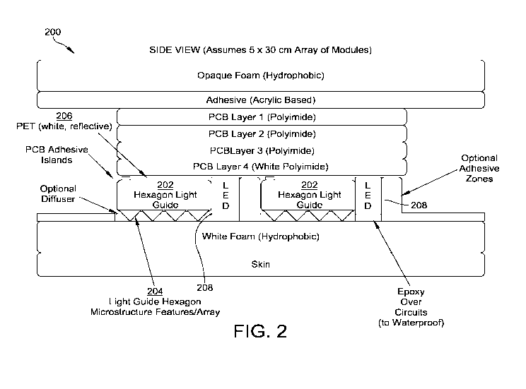
For example, Figure 2 illustrates a side view of a hexagon light guide and
electronics
layout 200. Figure 3 illustrates a top view of the hexagon light guide and
electronics layout 200.
The hexagon light guide and electronics layout 200 includes hexagon light
guides 202.
The hexagon light guides 202 illustrated in Figures 2 and 3 are composed of a
0.5 mm
medical grade PMMA (Evonik PMMA LJ19673/21/1 0.5mm thick material). On the
bottom
surface of the hexagon light guides 202, the surface is flat. On the top, a
pattern of micro-dots
204 is layered to evenly (uniformly) illuminate the entire light guide
surface. The pattern
accounts not only for side-emitting LEDs which illuminate the hexagon but
accounts for other
light diffusion surfaces that provide uniformity including a diffuser (if
needed) and the
hydrophobic/hydrophilic foams described above. Figure 2 has an internal
reflective surface
feature label which represents the pattern of micro-dots and other diffusion
surfaces.
A reflective PET layer 206 (which could be combined with other diffuser,
prismatic, or
polarizing materials) is used as a means to create an effect of total internal
reflection (TIR),
which allows the light emitted by side-emitting LEDs 208 respectively attached
to a side of each
of the hexagon light guides 202 to internally reflect light from one side of
the respective hexagon
light guide 202 to the other side.
The reflective PET layer 206 has a higher index of refraction than the
material of each
hexagon light guide 202 and the side-emitting light entrance of a given
hexagon edge allows
"most" of the light to go from a low index of refraction environment (for
example, air) into the
hexagon material above the critical angle needed for TR. The spacing of the
micro-dots 204 on
the top (the light emission surface facing the treatment site) or bottom of
the light guide creates a
mechanism for the light that is undergoing TIR to bounce out of the hexagon
light emission side
because the light angle changes enough to meet the boundary condition for
refraction (out of the
hexagon light guide surface) rather than reflection and continuing via TIR
down the remainder of
each of the hexagon light guides 202. The spacing of the micro-dots 204 is
generated to make
-23-
CA 03067541 2019-12-16
WO 2018/232163
PCT/US2018/037611
sure that light leaks (breaks the boundary condition) uniformity across the
hexagon light
emission surface.
In certain embodiments, a micro-array pattern of micro-dots can be placed on
the bottom
of the hexagon (facing the reflective white PET, residing below the non-light
emission surface
side of the hexagon), to generate uniform light emission from the top of the
hexagon towards the
treatment site. However, when one presses down on the hexagon light guides
202, a hot spot is
created, because the design assumes there is a small air-gap between the light
guide micro-dots
204 and the PET 206. When the unit is pressed upon the air gap disappears and
more light exits
the hexagon light guides 202 where there is no air gap. To avoid this problem,
the micro-dot was
placed on the top of the hexagon light guides 202 ¨ facing the PET
206/diffuser. This approach
or micro-dot pattern assumes the air gap is completely removed.
In certain embodiments, foams with adhesive coatings on top of the light-
emitting surface
of the light guide can cause light to bounce out of the light guide closest to
the LED input in the
light guide. A suitable micro-dot pattern to avoid the light existence from
the adhesive has not
been successfully developed. The adhesive generates an optical environment
that reduces TIR a
short distance from the LED input. The current solution is to apply foams,
diffusers, polarizers,
etc. without any adhesive that may make contact with the light guide light-
emitting surface.
However, adhesive on the foam, diffuser, and polarizer on the side opposite of
the light guide
contact side is permissible and can work with a given micro-dot pattern. The
adhesive could
consist of an acrylic adhesive, silicon adhesive, or a skin-friendly or trauma-
friendly adhesive.
To get light into the hexagon light guides, the primary mechanism is to use
side-emitting
LEDs from TechLED (Marubeni). The side-emitting LEDs commonly used for wound
care
applications emit 405nm light. In certain embodiments, three edges illuminate
the hexagon, as
illustrated in Figure 4. Figure 4 illustrates a view of side-emitting LED 400
placement. Given the
size of the current hexagon, three side-emitting LEDs can reside on each of
the three edges (total
of nine side-emitting LEDs per hexagon). In future versions, for a given edge,
each LED in the
array could emit different wavelengths for different wound healing therapeutic
purposes.
The backing layer composed of a foam can have adhesive on either side, as
discussed
below with respect to Figure 2. This adhesive layer would allow the PCB
components (but not
the light emission surfaces of any light guide) to stick to the foam backing.
It would also allow
foam (without any adhesive) which is on top of the light-emitting surface of
the light guide to
-24-
CA 03067541 2019-12-16
WO 2018/232163
PCT/US2018/037611
seal to the backing layer. The backing layer could contain other foam,
diffusers, polarizers, or
optical materials (transparent, semi-transparent, or opaque).
The PCB components, such as the LED drivers, LEDs, and other parts can be
domed with
epoxy to make the parts/circuits water proof. The following PCB can include
thermistors to
.. monitor temperature within the wound dressing. Data from the thermistors
can be sent back to
the power pack by a connector cable.
In an embodiment, a plurality, for example, three, of these wound dressings
can be
connected to one another and receive power from the power pack by the
connector cable. Hence
the units are stackable and modular. Multiple dressings (or zones) can be
powered through a
single connector which goes to the power pack. Multiple data lines from a
given dressing can
traverse through multiple dressings so as to only require one location to
acquire the data rather
than multiple ports per dressing.
Table 7 provides a description of an embodiment of a hexagon light guide and
electronics
layout according to one implementation. For example, the properties described
in Table 7 may
.. illustrate properties of an embodiment of the hexagon light guide and
electronics layout 200.
LIGHT GUIDE
Type Side-emitting illumination source, e.g., a Light
Emitting Diode (LED)
Shape Polygonal, e.g., hexagon
Size 5mm to 50mm in the longest dimension; e.g., 20mm
Thickness 0.100 mm to lmm; e.g., 0.500mm
Bottom Surface (facing In contact with PET white reflective material
PCB)
Top Surface (facing Composed of microstructures, microlenses, microdots
to direct light
treatment site/skin) out of the light guide based on total internal
reflection
Microstructure Features Typically under several hundred microns, < 100um
Microstructure Array Typically non-uniform to allow light to exit equally
across the entire
surface. Lower density (fewer microstructures) near the side-emitting
illumination source. Higher density (more microstructures) near the
center of the polygonal shape. Pattern can be linear, or two-
dimensional, where two-dimensional patterns typically assume side-
emission from multiple input faces and the microstructure pattern
emits from each side of illumination to the center of the polygon.
PCB
Shape Polygonal, e.g., hexagon with extra width where LEDs
are placed
Size 5mm to 50mm in the longest dimension; e.g., 20mm
Thickness 0.125mm to 1.6mm; e.g., 0.8mm
Material of PCB FR-4
-25-
CA 03067541 2019-12-16
WO 2018/232163 PCT/US2018/037611
LED
Location Attached to PCB (defined above)
Type Side-Emitting
Size (Footprint) 2.10 mm width, 0.6mm height, 1.0mm length (from lens to
back)
Size (Lens) 1.70 mm width, 0.6mm height, 0.5mm length
Lens/Optic FOV +/- 82 Degrees
X-Dim (Horizontal)
Lens/Optic FOV +/- 67 Degrees
Y-Dim (Vertical)
Radiated Power 20 mW
LED ARRAYS
LEDs in an Array LED Array could be composed of a single LED or multiple
LEDs.
Number of LEDs on any given side of a hexagon that is 20mm will be
up to 3 LEDs. Spacing between LEDs can be linear or non-linear
(linear preferred). Location of array along one side of a hexagon can
be symmetric or non-symmetric from center (symmetrically located
preferred).
Array Location If one side, assume a linear microstructure light guide.
In most cases,
assume two-dimensional microstructure and LEDs on more than one
side of hexagon. Assume an array on three-opposite sides with one
wavelength. All six sides of the hexagon could have an LED array.
Each side could have the same wavelength LED. 3-opposite sides of
the hexagon could have one wavelength while the other 3-opposite
sides of the hexagon could have another wavelength. For example, 3-
opposite sides of the hexagon could have an LED array that emits
405nm light and the other 3-opposite sides of the hexagon could have
an LED array that emits 680nm light.
LED Array A single array on any given side of a hexagon could
include more than
Wavelengths one wavelength. For example, within one array, assume 3
LEDs in the
array, could include two 680nm emitting LEDs and a single 850nm
LED.
LED Control Each LED could be individually controlled. Each LED array
could be
individually controlled (preferred for multiple wavelength variations),
or all LEDs on a single PCB could be controlled (preferred for single
wavelength, this is the current process)
OTHER MATERIALS
PET Reflective, white material laid down on PCB between the
LEDs/arrays
Conformal Coating Over electronics and LEDs (but not lenses) to protect
parts
Adhesive Zones On PCB to lay down PET and other floating materials
Thermally Conductive Manage heat transfer from LEDs and PCB away from skin and
out of
Heatsink Materials bandage. Thermally conductive materials include copper,
aluminum,
other. Surface area key element in reducing heat. Magnets may be
used as a mechanism to transfer heat.
Outer Dressing: Patient-contacting side/skin-side material may be
optically clear to
Silicones (Treatment maximize light throughput while minimizing light
output of LED and
Side) reducing thermal waste from each LED. Thickness 1 to 2
mm.
-26-
CA 03067541 2019-12-16
WO 2018/232163 PCT/US2018/037611
Outer Dressing: In some embodiments, it may be preferable to have a
silicone with
Silicones (Air Side) some heat transfer capability. NuSil provides (a
silicone material
(MED15-2980P and MED20-2955P) that is thermally conductive. Air
side silicone can be opaque, which can aid in reducing any light
projecting towards patient/outside observer's visual field.
Inner Dressing: Silicone with low durometer (<50) with diffusant. This
layer diffuses
Silicone (Interstitial) the LED point source light such that the irradiance
measured over the
LED is similar to that over the remainder of the hexagon light guide.
This layer also acts as a mechanical fixture to keep the hexagon light
guide in place in relationship to the LEDs and LED arrays.
Silicone over Foam Silicone may be implemented as a surface because it can
be optically
Outer Dressing or clear, non-adherent, and can be cleaned easily between
daily uses. It
Equivalent is also very flexible when it has a durometer between 10
Shore A to 60
Shore A (18-30 Shore A preferable). Also, by encapsulating opto-
electronics, the silicone can be ripped off after use and repackaged and
re-sterilized to take advantage of the long shelf-life of the opto-
electronic parts. Utilizing all silicone parts for the outer dressing along
with inner dressing makes it easier/simpler to adhere these materials
together with silicone adhesives or with over-molding.
Adhesive Zones on For burn wounds, no adhesive desired to avoid pulling at
tissue that
Outer Dressing may be healing. For chronic ulcers, like diabetic foot
ulcers,
potentially desirable to have adhesive.
Other Layers Other layers may include foams (hydrophobic or
hydrophilic),
polyurethanes, or other medical grade materials that are flexible,
durable, light-transmitting (patient contact side), and can aid in fluid
management.
Preferred fluid For burn wounds, silicone encapsulated bandage sits over
the top of a
management hydrogel placed in wound (for example, a hydrogel from
Advanced
Medical Solutions, Ltd). Hydrogel can be used on dry-wounds. For
low-medium-high exudating wounds, optimal dressing in the wound
for fluid management is a calcium alginate (for example, a calcium
alginate from Advanced Medical Solutions, Ltd), wetted or wet from
exudate.
HEXAGON SYSTEM
Single Hexagon Layers Primarily composed of PCB, PET, light guide, LED,
localized wire
(Locally) management system, localized interstitial silicone layer,
localized
silicone patient contacting side, localized thermally conductive
material(s) , localized thermally conductive silicone
Hexagon Layers All of the above but full silicone layers, wire
management, and
(Device) thermal conductive layers expanded around all hexagons.
Primary Hexagon Light 3x6 array, lilypad (center hexagon surrounded by 6
outside hexagons).
Patch Arrays in Use
Stacking Instead of larger array sizes, there is the option of
stacking the smallest
site arrays (i.e. the 3x6 array and lilypad)
Ideal Hexagon Size 20mm in longest dimension. Optimal range 5mm to 30mm in
longest
dimension.
-27-
CA 03067541 2019-12-16
WO 2018/232163 PCT/US2018/037611
Ideal Hexagon Array 3x6 array, lilypad (for example, Figure 9), and large
blanket (3 ft. x 3
Sizes ft. or lm x 1m)
Large Blanket Sizes 50 x 50 hexagon array or an array of stacked 3x6 arrays
or stacked
lilypads
Ideal Hexagon Array 3x6 array, lilypad (for example, Figure 9)
Size for 5%-to-15%
TBSA Burn
Ideal Hexagon Array Large blanket (3 ft. x 3 ft. or lm x 1m)
Size for > 15% TBSA
Ideal Hexagon Size for 3x6 array, lilypad
Chronic Ulcers
(Diabetic Foot and
Pressure Ulcers)
Array of Hexagon lx 1, 3x3, 3x6, 6x6, 3x12, 12x12, 25x25, 50x50;
specifically 3x3, 3x6,
Range (when Hexagon and 50 x 50
Diagonal = 20mm)
Hexagon Size Range 5mm, lOmm, 15mm, 20mm, 25mm, 30mm, 35mm, 40mm, 45mm,
(Based on Diagonal) 50mm; specifically 20mm for flexibility around arm,
wrist, leg. 5mm
ideal for smaller extremities like fingers. 50mm ideal for large flat
surfaces like chest, back, or thigh.
HEXAGON ARRAY SPACING
Spacing Between Balance between spacing, flexibility, and light coverage.
Preferred
Hexagons gap between hexagons is between 0.5mm to 3.00mm, with an
ideal
distance of 1.5mm to 2.00mm.
Problem of small air When bending hexagons overlap and crash into near
neighbors.
gap
Problem of large air Light uniformity decreases.
gap
WAVELENGTH AND IRRADIANCE
Wavelength Range 380nm-430nm; for example, 405nm plus/minus lOnm. Other
ranges
(Wavelength 1) of interest 425nm plus/minus lOnm and 470nm plus/minus
lOnm.
Wavelength Range 650nm-700nm; for example, 675nm plus/minus lOnm. Other
ranges
(Wavelength 2) of interest 625nm plus/minus 15nm and 690nm plus/minus
15nm
Wavelength Range 830nm plus/minus 20nm. Other wavelengths of interest
810nm
(Wavelength 3) plus/minus 20nm and 850nm plus/minus 20nm.
Wavelength 1 1mW/cm2 to 10mW/cm2; for example, 3mW/cm2
Irradiance Range
Wavelength 2 0.3mW/cm2 to 2mW/cm2; for example, 0.75mW/cm2
Irradiance Range
Wavelength 3 0.3mW/cm2 to 2mW/cm2; for example, 0.75mW/cm2
Irradiance Range
DURATION OF TREATMENT/WAVELENGTH
Duration of Treatment 24 hours continuously or pulsed.
Wavelength 1
Pulsed Treatment 5 min. on/off, repeat up to 24 hours. If pulsed, vary
irradiance by 2x
Wavelength 1 the irradiance of the continuous treatment. In one
embodiment, range
-28-
CA 03067541 2019-12-16
WO 2018/232163
PCT/US2018/037611
of pulsing 5 min. on/off up to 30 min. on/off. Asynchronous pulsing
is an option (i.e. 10 min. on / 5 min. off, repeat).
Duration of Treatment Greater than 6 hours of continuously or pulsed
treatment. 12 hours to
Wavelength 2 and 3 24 hours ideal.
Combination of 6 hrs. continuously of wavelength 1 followed by 18
hours of
Wavelengths 1 and 2; 1 wavelength 2 or 3 or a combination of wavelengths 2 and
3.
and 3; and 1, 2, and 3 Alternatively, wavelengths 1, 2, and / or 3 run
simultaneously up to 24
hours.
PULSE WIDTH MODULATION
Wavelength 1 PWM Pulse Width Modulation (PWM) is used to tune the
irradiance level by
turning on and off the illumination at 10 to 100 Hz (Tyler range).
Wavelength 1 will have a PWM of 25% to 75%.
PWM Waveform Type Synchronous and asynchronous
PWM Waveform Square wave
Pattern
Wavelengths 2 and 3 Low PWM value to account to lower irradiance
requirement.
PWM
Thermal Management Vary PWM to control thermal temperature
Visual Perception During off-time during treatment cycle, to help aid
people in realizing
the device is still on and running, one can set the PWM in the 1%-to-
10% range rather than 0% and then raise the PWM back to peak value
when the treatment cycle is supposed to be on.
SENSORS
General Description Device has sensors that relay information regarding
the wound to the
power-pack or via wireless communication to a computer
POWER PACK
General Description Device is controlled and powered by a wearable
lightweight power
pack that can run off battery or wall outlet and controls the LEDs
USE-CASE
Example 1 Device is placed directly on the surface of the skin,
skin orifice,
endothelial or epithelial surface, skin wound or implanted within the
body or onto an implantable medical device (e.g., prosthesis)
Example 2 Can be left in contact with the patient continuously for up
to 7 days
Table 7: Example hexagon light guide and electronics layout description.
In at least one embodiment of light patches disclosed herein, light is
generated by LEDs.
LEDs may generate heat, which may raise the temperature of the light patch. In
some
embodiments, it may be disadvantageous for the light patch to be raised to
above 41 C at a
required light dose. The LEDs may be pulsed using Pulse Width Modulation (PWM)
to modify a
total irradiance of the patch, and to reduce the total heat that is generated
by the light patch.
A material of the light patch and of an associated PCB may be selected to
reduce a
temperature of the bandage. For example, a first design may be directed
towards thermal
dissipation with two, four, and six-layer boards using standard FR-4 and
loz/ft of copper. A
-29-
CA 03067541 2019-12-16
WO 2018/232163
PCT/US2018/037611
second design may include a four-layer, 2 oz copper board. A third design may
include
alternatives to FR-4 including, for example, a metal core.
Other thermal management techniques may include changing the layers
surrounding the
light patch opto-electronics (for example, layers encapsulating the LEDs) by
considering: adding
more silicone/polyurethane to a patient side of the light patch to increase
the temperature barrier;
using optically clear materials to reduce LED power requirements; adding heat
sinking materials
to the back of each hexagon PCB; or pulsing a certain number of hexagons at
any one instant,
faster than the human eye can see.
The optics around the light patch may be optimized to be delivered using
hexagonal light
guides with LEDs on 3 edges; where each light guide and LED array is situated
on a rigid PCB
that is also hexagon-shaped. To allow the system to bend, all the flexing may
occur between the
hexagon PCB islands. Rigid flex circuits may be used for connecting the PCB
islands, but
traditional rigid flex boards may not allow for enough flexibility in the
small space allowed
between hexagons, which may be between approximately 1.3 to 2.0 mm. As an
alternative, thin
(28 gauge) wire may be used to connect multiple hexagons together. For
example, Figure 34
illustrates a top view of multiple hexagons 3400 connected by thin wire.
The layout of Figure 34 may be problematic from a manufacturing perspective
and may
have reliability issues in regard to stress on solder joints, particularly if
the Hexagon PCB islands
are flexed often and/or with extreme bending forces. Accordingly, one of at
least three solutions
may be implemented according to the foregoing disadvantages.
In a first solution, flat flexible cables may be used. For example, surface
mount or
through-hole flat cable jumpers may be used to connect the array of hexagons
together. Figure 35
illustrates a top view of a flat flexible cable 3500 according to an
embodiment. Figure 36
illustrates a top perspective view of another flat flexible cable 3600
according to an embodiment.
In the embodiments illustrated by Figures 35 and 36, either surface mount or
through hole
connectors styles could be used such that the connections between hexagon PCBs
could be made
while still in the panel or at any more efficient stage in the PCB
fabrication/assembly process.
In a second solution, a conductive material may be adhered to each of the
hexagon PCB s
for electrical connections. For example, conductive ink may be printed onto a
plastic sheet or a
copper foil with a Kapton backing to be used for the electrical connection.
The hexagon PCBs
are still rigid PCBs but are connected by ¨ ideally one ¨ flexible circuit.
Figure 37 illustrates a
-30-
CA 03067541 2019-12-16
WO 2018/232163
PCT/US2018/037611
layout of a back plane connection layout 3700 according to an embodiment.
Figure 38 illustrates
a layout of a back plane connection layout 3800 according to another
embodiment.
In a third solution, a ZIF style connector may be used to connect each hexagon
to one flat
flex circuit. The flexible PCB may designed to connect all the hexagon PCBs in
the 3x6 array
together in a simpler process than soldering multiple connections. For
example, Figure 39
illustrates shows a layout design for a flat flexible circuit 3900 according
to an embodiment. The
arrows show the direction and approximate location of the connector located on
each of the
hexagon PCBs in this potential arrangement of connectors. The half hexagon
will contain the
connection out to the power source. The flat flexible circuit could be made to
most easily be fit
into place, reducing the number of individual hexagon-to-hexagon connections
to be made.
Power Pack
In an embodiment a device comprises a power pack. In an embodiment the power
pack
is comprised of the following:
= Rechargeable Battery
= PCB control module
= Power/Data Cable
= Separate Power Recharge Station for Depleted Batteries
The rechargeable battery can be inserted and removed from the
structure/housing of the
power pack. When fully charged, the battery will last up to 8-24 hours. Upon
charge depletion, a
new fully charged battery needs to be inserted to continue therapy. The
depleted battery will
need to be recharged on the separate power recharge station.
In an embodiment:
= The power pack is configured to receive power from a wall outlet.
= The power pack is configured to provide warning indicators using LEDs,
sound, and/or
displays.
= The power pack is configured to allow data from the wound dressing to be
processed and
analyzed in the power pack.
= The power pack could send data to a wireless server or network to record
data and take in
instructions or regiment information to individualize treatment.
-31-
CA 03067541 2019-12-16
WO 2018/232163
PCT/US2018/037611
Array
Embodiments of the present disclosure further include varying the size and
shape of each
light module, as well as the spacing between adjacent light modules.
Embodiments of the device include a light patch that is designed and built out
of fiber
optics. The fiber optics are in a bundle at one end which receives light from
an LED source and
then the light undergoes TIR through the fiber up to the other end. At the
other end the fiber
optics fan out into a flat array as shown in Figure 5. Figure 5 illustrates a
fiber optic light guide
500, used for photodynamic therapy applications, where red lines indicate
fiber optics and where
each of the fiber optics is 0.5 mm in diameter. The fiber optic channels in
the flat array zone are
etched in a way to allow light to exit the TR condition and refract out of the
fiber optics. The
etch is optimized to create a uniform light leakage over a 10 cm x 10 cm area.
This design is very flexible and efficient, particularly when the device is
bent causing
"tipping" (generating a bend with a radius of curvature in one-dimension). The
reason the device
is flexible is because the light guides are not a "single body" so they allow
tipping and some
"tilting." Tilting is a bend in the device where the bend has a radius of
curvature in one-
dimension; typically orthogonal to the tipping bending direction. The light
delivery and
uniformity is efficient because the light is already in the body of a given
light guide channel or
fiber optic channel if there is any bending (or tipping).
Due to manufacturing complexities with fiber optics, embodiments include a
bandage
that utilizes a "single body" light guide as shown in Figure 6(a). Figure 6(a)
illustrates a solid
body light guide design 600 for even-illumination phototherapy applications.
Figure 6(b)
illustrates an example implementation 602 of the solid body light guide design
600 according to
an embodiment. Figure 6(c) illustrates a power pack 604 corresponding to the
example
implementation of the solid body light guide design 600 according to an
embodiment.
Instead of discrete light guide channels like fiber optics the light guiding
activity occurs
in a single device (plate) which receives light from multiple and overlapping
light sources (for
example LEDs). The single body light guide design 600 is 0.5 mm and can
receive light from
side emitting LEDs in an array attached to a flexible PCB, wherein the red
arrows illustrated in
Figure 6(a) indicate light rays from the LEDs. This design is easier to
produce and it does allow
for bending/flexibility for high radius of curvatures such as the chest wall
(typically after
-32-
CA 03067541 2019-12-16
WO 2018/232163
PCT/US2018/037611
mastectomy for a woman who has cutaneous metastases of breast cancer). The
design also
allows for more uniform and repeatable uniformity across the light guide
surface. However, this
design is not very flexible because now the light guide (compared to fiber
optic channels
separated from one another like in Figure 5) is a single body so it retains
rigidity despite the
initial flexibility of the 0.5 mm thick material. Additionally, light may NOT
be in the body of the
light guide channel if there is any tipping (particularly extreme tipping).
As an alternative to the fiber optic system or the single body light body
approach,
embodiments of the device further include an LED array allowing flexibility in
not only one
dimension but in both the vertical and horizontal direction. For example,
Figure 7(a) illustrates a
top view of an LED array 700 approach to flexible light delivery. Figure 7(b)
illustrates a side
view of the LED array 700 approach to flexible light delivery.
In embodiments the devices described here have improved flexibility over fiber
optic
channels, and are configured to optimize evenness of illumination, for
example, from an LED
array which might otherwise have issues with even illumination due to the
divergence of the
light from the top emitting LED. Another problem causing a lack of uniformity
is the inability to
diverge and homogenize the light in such a short throw distance from the LED
to the skin (it is
several millimeters).
With fiber optics (Figure 5) the device embodies flexibility (primarily in one
dimension)
but low light uniformity and is difficult to manufacture. With the single body
light guide (Figure
6[a]) the device is configured to have light uniformity but limited
flexibility in both dimensions
but the device is much easier to manufacture. With a discrete LED (light)
system (Figures 7A
and 7B) the design achieves two-dimensional flexibility and manufacturing is
fairly easy, but
uniformity can be compromised.
In embodiments the devices disclosed herein provide discrete light emission
channels
with at least two-dimensional flexibility and have the capability of emitting
uniform light over a
low profile (small thickness) in conjunction with ease of manufacturing.
One approach is to design the single body light guide to act as the fiber
optic channels by
breaking the single body light guide into an array of smaller single body
light guides as shown in
Figure 8. Figure 8 illustrates discrete light guides 800.
With the design in Figure 8, the approach creates "pivot points" for tipping.
Tilting is still
limited. Compared to a single body light guide, this design approach reduces
having light already
-33-
CA 03067541 2019-12-16
WO 2018/232163
PCT/US2018/037611
in the light guide at the pivot points. The main drawbacks to this approach
are that primarily only
one axis has increased flexibility and, since the light is diverging, as
indicated by the red lines in
Figure 8, there may be a decrease in the irradiance at the top of each light
guide channel,
particularly if the length of the channel is long, for example, over 50 mm.
An alternative approach to long/elongated but smaller single body light guides
is to
develop small but multi-faceted shapes that allow light to enter the light
guide from multiple
inputs to create uniformity while also creating a functional shape that allows
for multiple
deflection or multiple dimensions of flexibility. An optimized shape that
meets these criteria
includes hexagons as shown in Figure 9. Figure 9 illustrates a hexagon design
900. This design
also addresses the light divergence problem of long light guides and avoids
the excessive throw
distance/height of an LED array needed to get uniform coverage.
In Figure 9, each hexagon is isolated, tied by a thin flex circuit.
Flexibility is enabled on
six planes, and each hexagon has a single LED. Each hexagon provides even
illumination, which
eliminates the diffusion problem of the LED array, and the hexagon surface
area improves the
light divergence issue.
Other polygon shapes can be used. For example, Figure 10 illustrates an
octagon design
1000. However, the hexagon shape is desirable because it allows for a wide
degree of flexibility
across multiple pivot points but without sacrificing continuous illumination
between the spaces
(aka "dead zones") between each discrete light guide. As can be seen in Figure
10, there are
.. much larger dead zones between each light guide, such that there will be a
much larger effect of
light falloff from light guide to light guide and the area in the dead zone
will be dimmer/darker
compared to the light exiting a given light guide. The dead zone and
brightness effects can be
minimized with a hexagon-shaped array compared to some other polygon shapes.
Other shapes
like triangles and squares could be good light guide shapes but with
triangles, light uniformity
from multiple edges could be a problem and an array of closely stacked squares
(or rectangles)
will have to deal with a greater number of issues pertaining to dead zones,
light uniformity, and
potential buckling when the array is bent.
In one embodiment, a preferred size is of importance based on flexibility
required, the
light output (expressed in milliWatts [mW]) of the LED, and the light input
required for a
therapeutic response. Assuming that a pivot point is based on the longest
diagonal of a hexagon,
then the size (or diagonal) of the hexagon should be set so that the smallest
hexagon can pivot
-34-
CA 03067541 2019-12-16
WO 2018/232163
PCT/US2018/037611
around the smallest-sized anatomy required for treatment. If a finger is to be
treated with light,
for example, then an ideal size for a hexagon light guide is 10 to 15 mm along
the diagonal. For a
leg or torso, the hexagon size could be larger, such as approximately 50 mm.
A tradeoff on the hexagon size is that smaller hexagons require more LEDs if
the
hexagons are built into an array that will cover a larger surface body area.
As the hexagon size
gets larger, the LED requirements also increase ¨ depending on the irradiance
required. If the
light output out of the light guides needs to be above 1 mW/cm2, then the LED
has to have a
large output, when coupled as an LED array, to achieve the irradiance over a
large throw (light
divergence) distance. Essentially, there comes a point where a large hexagon
becomes as big as,
or functions just like, the single body light guide as discussed in Figure
6(a).
For arms and legs, a preferable hexagon size is between 15 mm to 25 mm with 20
mm
and 22.5 mm as a most preferable size. For fingers, nose, or ear anatomy, a
hexagon size of 10
mm to 15 mm is most preferable. For larger anatomical surfaces, 35 mm is
preferably the
maximum hexagon size.
The gap between hexagons or each individual polygon is important. The gap
provides the
pivot points and flexibility. The gap also provides the areas where the
individual light guides and
circuitry are connected and where some hard-mounted circuits such as the LEDs,
resistors, LED
drivers, and other items, sit. In embodiments an optimized gap allows for
flexibility and
placement of electronics while at the same time minimizing dead zones (areas
where light is not
present and where light is uniform from one polygonal light guide or emission
surface to the
next) and making sure that, as the entire electro-optical system is bent, the
individual light guides
do not crash into each other. For the hexagon, an exemplary gap size is
between 0.75 mm and
2.50 mm for hexagon sizes ranging from 15 mm to 25 mm, respectively. For
hexagons that are
sized 22.5 mm, an exemplary gap is approximately 1.6 mm. In general, the
preferable gap to
diagonal width of a hexagon, as pertaining to a percentage, is between 5% and
10%.
As for the layers connecting the individual hexagon light guides, there are,
in
embodiments, one or more polyimide layers that include electrical traces and
positional features
to solder LEDs, resistors, pulse-width-modulators, LED drivers, MOSFETs,
amplifiers, and
other basic electrical components. In embodiments, the layers are between 25
p.m to 500 p.m
thick and although the layers are thin between the hexagon light guides, there
is a more rigid
-35-
CA 03067541 2019-12-16
WO 2018/232163
PCT/US2018/037611
(thicker) layer behind the light guides and where the LEDs sit so as to
provide greater reliability
to the core light-emitting objects even when the connection layers are being
flexed.
In embodiments, connections between the individual hexagon light guides can be
flat
bridges or could be multiple flex connections. For example, Figure 11 flat
connections 1100
between light guides of an LED and light guide array, and Figure 12
illustrates multiple flex
connections 1200 between components of an LED and light guide array.
Additional sensors
(temperature sensors, pH sensors, capacitance sensors, etc.), can be dispersed
around the primary
connections between the individual light guides.
Pulsing
Killing organisms requires light, a photosensitizer, and oxygen.
Administration of the
light at higher irradiance depletes the endogenous photosensitizer and 02. In
some settings, such
as in hypoxic wounds, the light can be pulsed with 2 to 10 minute dark periods
to allow the
organisms to produce photosensitizer and restore the tissue oxygen tension.
The dark periods
.. may need to be longer for certain parasites, such as roundworms and flat
worms, where cell
multiplication is much slower and requires heme from the host. In this setting
the dark time may
be 1 to 4 hours.
Pulsing the light source from light (ON) to dark (OFF) can provide benefits
from a
microbiology perspective and a device-based perspective. From a microbiology
perspective,
when delivering low-irradiance at a higher threshold, pulsing the light will
effectively reduce the
total number of photons delivered and the rate of oxygen and photosensitizer
completion
(photosensitizer in this case would refer to photoacceptors, porphyrins,
flavonoids,
chromophores, etc. already endogenous to the bacteria). The period between
dark periods can
allow the oxygen levels and photosensitizer to recuperate, thereby allowing
for the treatment to
be performed continuously ¨ over 24 hours to 72 hours or longer. The dark
period should be
sufficiently long to account for the intensity or irradiance delivered by the
light-source such that
for higher irradiances a slightly longer dark period would be beneficial
compared to lower
irradiances, where a slightly shorter dark period would be beneficial.
Simultaneously, the dark
period should not be overly long such that bacteria are replicating
(multiplying) or too short such
that no further bactericidal effects can occur naturally (other than thermal
damage) when the
-36-
CA 03067541 2019-12-16
WO 2018/232163
PCT/US2018/037611
biologically affected area has depleted levels of oxygen or photosensitizer
elements available
such that any photons delivered to this area cannot adequately start the ROS
process.
Pulsing the light source to go from light to dark has an advantage for the
device
delivering the light. Higher irradiance and/or long-duration light delivery
requires significant
power to emit light continuously to a given treatment site. Pulsing the light
source will turn the
light off for a given time period which will effectively reduce the power
required. This aids in
the device when it is running off an external battery system that requires
recharging once the
power is depleted. If power is conserved by pulsing the light source, the
external battery can
maintain a charge longer while in operation, thereby allowing for a longer
time period between
recharging the battery by the user.
Pulsing the light source can by symmetric (for example, 5 minutes On and 5
minutes Off)
or asymmetric (for example, 20 minutes On and 10 minutes Off; or 10 minutes On
and 20
minutes Off). The pulsing can consist of different pulses so that the light
intensity changes
during the pulse. The pulse can be a square wave, triangle wave, trapezoid
wave, sinusoidal
wave, etc. The pulsing rate and pulse wave type can change in time during a
given treatment.
The pulsing rate and pulse wave type can vary for any given wavelength emitted
by the device or
system. The pulsing time can be under 1 second, 1 minute, 1 hour, or up to 1
day.
Combination Therapies
Devices and methods disclosed herein can be used with adjunctive or additional
therapeutic modalities, for example, methods described herein can be used in
combination with
an antibiotic, for example, antibiotic primary organisms involved in skin/soft
tissue infections,
which include Staphylococcus aureus (MRSA methicillin RSA and MSSA
methycilllin) and
Staph epidermidis. (coagulase-negative Staph). For these types of infections,
methicillin is most
commonly prescribed, followed by vancomycin or doxycycline. As an adjuvant to
antibiotic
therapy, rifampin is prescribed in conjunction with these drugs given its anti-
biofilm properties
for Staph species (it does not kill off the bacteria, but has been shown to
penetrate through the
biofilm).
In addition to Staph species, the other more significant risk for skin and
soft tissue
infections is Pseudomonas, which is most often managed through Cefepime, Zosyn
and
Carbapenems.
-37-
CA 03067541 2019-12-16
WO 2018/232163
PCT/US2018/037611
Methods and devices described herein can be used with drugs from Tables 3 and
4,
below.
Methods and devices can be used with or without photosensitizers or dyes, for
example,
photosensitizers from Table 1.
Table 1: Dyes and Photo sensitizer
# Trade Name Molecule
1 ALA 5-aminolevulinic acid
2 Foscan Meta-tetra(dyroxyphenyl) chlorin
3 Lu-Tex Lutetium texaphyrin
4 NPe6 Mono-L-aspartyl chlorin-e6
5 Pc4 Silicon phthalocyanine
6 Photochlor Hexyl ether pyropheophorbide-a derivate
7 Photofrin Hematoporphyrin derivative
8 Photolon Chlorin-e6-polyvinylpyrrolidone
9 Photo sens Aluminum phthalocyanine
Purlytin Tin ethyl etiopurpurin
11 Tookad Palladium-bacteriopheophorbide)-a
12 Visudyne Benzoporphyrin derivative monoacid ring A
In addition to the dyes and photosensitizers described in Table 1, other dyes
or
photosensitizers include St. John's wort, topical toluidine blue, methyl blue,
and all other
acridine dyes likely placed on the skin surface, on the biofilm, or on the
wound bed.
Sensors and Processors
In embodiments, the device includes sensors, for example, for monitoring a
parameter,
for example, at the site of irradiation. For example, responsive to a signal
from the sensor
indicating, for example, an increase in temperature, the device or a processor
or computer
connected thereto alters an activity. For example, if the temperature rises,
the pH drops, and
turbidity increases, this signals that an infection is developing and alerts
the user.
-38-
CA 03067541 2019-12-16
WO 2018/232163
PCT/US2018/037611
Pathogens
Devices and methods of the invention can be used against a broad spectrum of
pathogens,
including bacteria, fungi, protozoans, and parasites. Devices and methods of
the invention can
be used against gram positive bacteria and gram negative bacteria.
Some pathogens require a higher energy level. Because of heat and other
concerns, it may
be desirable to start with a higher symmetry value reflecting the need for a
higher energy level,
but as that pathogen is killed or neutralized to decrease the symmetry value.
Klebsiella is a gram negative facultative anerobe, and ferments lactose. A
relatively
higher energy level is needed to kill or neutralize it. Klebsiella lives in a
lower 02 environment,
so it may need more intervening periods. Klebsiella also fixes N, which may
deplete free
radicals, making it more difficult to kill or neutralize.
Bacterial pathogens which can be treated with devices and methods described
herein are
provided in Table 3. Fungal infections can be treated with devices and methods
described herein.
Protozoans are traditionally found in aqueous environments in a wide range of
trophic levels.
Parasitic protozoans exhibit osmotrophy, a process by which they imbibe the
nutrients from their
environment directly, as they are mostly present in nutrient-rich
environments. An interesting
feature about these parasitic protozoans is their dramatic life cycle. The
reproductive cycle
includes short generation times, and alternates between an infective
proliferative stage and a
dormant cyst stage. Parasitic protozoa that affect humans are provided in
Table 2
-39-
CA 03067541 2019-12-16
WO 2018/232163
PCT/US2018/037611
Table 2: Parasitic protozoa that affect humans
= Entamoeba histolytica (causes amoebiasis)
Exoparasites, not related to burn risk:
= Toxoplasma gondii (causes oxoplasmosis)
= Cryptosporidium (causes cryptosporidiosis)
= Trichomonas (causes trichomoniasis)
= Trypanosoma cruzi (causes Chagas disease)
= Leishmania (causes leishmaniasis)
= Trypanosoma brucei (causes African trypanosomiasis)
= Naegleria fowleri (causes Naegleriasis)
_
Parasites will now be discussed in greater detail.
Trypanosoma cruzi. More than 300,000 Americans are infected with Trypanosoma
cruzi,
the parasite that causes Chagas disease, and more than 300 infected babies are
born every year.
Chagas disease is transmitted through a bite from the triatomine bug, which
then deposits its
feces in the skin opening. Chagas disease can cause long-term digestive,
cardiac, and
neurological complications. Death from the infection is often caused by heart
attack. However, if
caught early, the condition is easily cured with medication.
Cysticercosis. This parasitic infection, caused by the taenia solium tapeworm,
makes its
home in human tissues such as the brain and muscles. Larval cysts from the
parasite form in the
body and can cause a number of complications, including seizures. There are at
least 1,000
hospitalizations for cysticercosis per year in the U.S. This tapeworm
infection is often the result
of eating uncooked pork that contains larval cysts.
Toxocara. Approximately, 13.9 percent of the U.S. population has antibodies
against this
parasitic infection. Sadly, the rest of us are at risk for acquiring it
through roundworms often
found in the intestines of dogs and cats. About 14 percent of Americans have
had exposure to
toxocara, and at least 70 people die from the infection each year. According
to the CDC, most of
the infections are in children and many suffer blindness due to related eye
disease.
-40-
CA 03067541 2019-12-16
WO 2018/232163
PCT/US2018/037611
Methods and devices described herein can be used to treat subjects having a
drug
resistant pathogen, for example, a pathogen from Table 3 or a pathogen
resistant to a drug from
Table 3 or 4.
Table 3: Bacteria and resistance
# Bacteria Type Antibiotics Resistant
1 Acinetobacter baumannii Carbapenem
2 Pseudomonas aeruginosa Carbapenem
3 Enterobacteriaceae Carbapenem, ESBL-producing
4 Enterococcus faecium Vancomycin
Staphylococcus aureus Methicillin-resistant, Vancomycin-intermediate
6 Helicobacter pylori Clarithromycin
7 Campylobacter spp. Fluoroquinolone
8 Salmonellae Fluoroquinolone
9 Neisseria gonorrhoeae Cephalosporin-resistant, Fluoroquinolone-
resistant
Streptococcus pneumoniae Penicillin-non-susceptible
11 Haemophilus influenzae Ampicillin
12 Shigella spp. Fluoroquinolone
5
-41-
CA 03067541 2019-12-16
WO 2018/232163
PCT/US2018/037611
Table 4: List of Drugs
# Drug
1 Ampicillin - Ciprofloxacin
2 Methicillin
3 Vancomycin
4 Doxycycline
Carbapenem
6 Cefepime
7 Zosyn
8 Fluoroquinolone
9 Clarithromycin
Cephalosporin
11 Penicillin
_
Killing organisms requires light, a photosensitizer, and oxygen.
Administration of the
light at higher irradiance depletes the endogenous photosensitizer and 02. In
some settings, such
5 as in hypoxic wounds, the light needs to be pulsed with 2-10 minute dark
periods to allow the
organisms to produce photosensitizer and restore the tissue oxygen tension.
The dark periods
may need to be longer for certain parasite such as roundworms and flat worms
where cell
multiplication is much slower and requires heme from the host. In this setting
the dark time may
be 1-4 hours.
10 Targets for irradiation treatment include burns, ulcers, and points of
percutaneous entry.
The target can be on a surface of the subject, for example, the skin or the
surface of a wound, or
the surface of any natural orifice.
Burn patients' wounds are kept in an aqueous environment to prevent
desiccation of the
burn wound. Pseudomonas and MRSA are therefore the most common contaminants in
these
wounds and can cause infection. Pseudomonas thrives in an aqueous environment.
In addition,
Candida albicans is a yeast that can be killed with 405nm light and is also
very common in moist
environments.
-42-
CA 03067541 2019-12-16
WO 2018/232163
PCT/US2018/037611
Free radicals that interfere with bata lactamse production, such as VRE, can
convert
MRSA to make it penicillin sensitivity. The bacteria has plasmids, they code
for small molecules
that form Ab resistance. Free radicals poke holes in the cell membrane. They
may also damage
the ER.
Targets include natural orifices and the contents thereof, for example, the
oral cavity,
nasal passages, urethra, anus, vagina, and ears. Thus infections that enter
through, or occur in, a
natural orifice can be treated with continuous low-irradiance and the devices
that deliver
continuous low-irradiance. Included are infections, for example, bladder
infections and
prostatitis where the organisms swims up the urethra, and sinusitis with the
organism comes in
through the nasal passages, ear canal, etc. Method and devices disclosed
herein can be used to
treat iatrogenic infections in which the organism gains access through a
puncture (intentional or
otherwise) made through the skin or other tissue, for example, a puncture
occurring with a via or
a catheter to generate infections, for example, central line infections,
arthroscopy infections, etc.
or percutaneous implants infections.
NEGATIVE PRESSURE WOUND THERAPY AND NON-ADHERENT WOUND BED-FACING MEMBERS
Devices described herein can be configured to place the wound bed at sub-
atmospheric
pressure, sometimes referred to herein as negative pressure wound therapy
(NPWT). Unwanted
substances, including exudates that inhibit healing, or materials that
comprise infectious agents,
or mediators of inflammation, for example, T cells, B cells, or macrophage,
can thus be
suctioned away and the amount thereof reduced at the wound bed.
Devices described herein can be configured to comprise a non-adherent member
adjacent
to the wound bed. In embodiments this optimizes healing, minimizes, reduces,
or inhibits, the
growth or level of unwanted organisms, for example, a bacterium, spore, or
fungal element, and
.. minimizes negative effects of dressing changes or device removal.
These embodiments can also be combined. Thus, in embodiments a device
described
herein is configured to provide NPWT and a non-adherent member adjacent to the
wound bed.
Components for use in the devices described herein can be adapted from known
components, see, for example, US 8,444,611, US 7,857,806, US 7,534,240, US
5,636,643, US
9,717,829, US 9,642,950, US 9,352,076, US 9,302,034, US 9,089,630, US
8,772,567, all of
which are hereby incorporated by reference.
-43-
CA 03067541 2019-12-16
WO 2018/232163
PCT/US2018/037611
In an embodiment a light-emitting element, for example, an array of a
plurality of light
emitting modules, is disposed between the wound bed and a gas-impermeable
member which
allows a pressure differential between the wound bed, or the space defined by
the gas-
impermeable membrane (the reduced pressure space), and ambient atmosphere. The
gas-
impermeable member separates the wound or the reduced pressure space from the
outside
environment, and allows the negative pressure to act on the area of the wound.
In embodiments
the gas-impermeable membrane forms a seal with the surface of the subject.
The reduced pressure space is typically configured to be continuous with a
vacuum or
reduced-pressure source, for example, a suction device, for example, a pump,
or wall suction.
The connection to the vacuum source can be controlled, for example, by a
valve. The valve or
application of negative pressure can be under manual control, computer
control, or both. The
application of vacuum can be programmed to occur at predefined times, periods,
or conditions.
The reduced pressure space can be connected to the source of vacuum by way of
a fenestrated
tube or disc.
In an embodiment the application of negative pressure is constant throughout
the use of
the device or throughout a portion of the time the device is contacted with
the subject. In
embodiments, the device is configured to allow different pressures, for
example, at different
times of the day, at different stages of treatment or healing, or with
different wavelengths of light
being applied. For example, in an embodiment a first level of negative
pressure is applied at a
first point of a preselected period, for example, a 24 hour period, and a
second level of negative
pressure is applied at a second point of the preselected period. In an
embodiment a first level of
negative pressure is applied at a first stage of healing or treatment, and a
second level of negative
pressure is applied at a second stage of healing or treatment. In an
embodiment a first level of
negative pressure is applied during irradiation at a first wavelength, and a
second level of
.. negative pressure is applied during irradiation with a second wavelength.
In an embodiment a
high level of negative pressure (more suction) is applied during irradiation
with a first
wavelength and a lower level of negative pressure is applied during
irradiation with a second
wavelength. In an embodiment the first wavelength is shorter than the second
wavelength, for
example, the first wavelength comprises light in the blue region of the
spectrum and the second
wavelength comprises light in the red region of the spectrum. Control of
pressure can be effected
automatically or manually. Control can be effected by a device, for example, a
device
-44-
CA 03067541 2019-12-16
WO 2018/232163
PCT/US2018/037611
comprising a computer or microprocessor, which device can also control other
parameters, for
example, wavelength, intensity, temperature, and the like.
Application of vacuum can be continuous or intermittent. In an embodiment
negative
pressure is provided at between -75 mm Hg to -125 mm Hg.
Devices described herein, for example, devices configured for providing
negative
pressure at the wound bed, can include a non-adherent member disposed adjacent
to or in contact
with the wound bed, for example, disposed between the subject, for example,
the wound bed, and
other elements of the device, for example, an array of a plurality of light
emitting modules. In
embodiments the non-adherent member minimizes fibroblast, keratinocyte, or
other cell growth
into the device or a component of the device such as the non-adherent member.
In embodiments
growth into the non-adherent member is minimized as compared to what is seen
with a porous
material, for example, an open cell foam or gauze. The non-adherent member
allows separation
from the wound bed, for example, in changing a dressing, or removal or
adjustment of a device
described herein with minimized removal of new cells. In an embodiment use of
a non-adherent
.. member, or other material that minimizes open cells, minimizes bacterial
growth, which can
occur in the cells of porous materials.
Non-adherent members, for example, a light-emitting element, for example, an
array of a
plurality of light-emitting modules, can comprise a synthetic rayon mesh
material, a closed-cell
foam, or low-surface coatings and materials. In embodiments the non-adherent
member
comprises a woven element, for example, gauze, coated with a non-adherent
material, for
example, Teflon or polytetrafluoroethylene. In an embodiment a non-adherent
member
comprises a Telfa coated woven mesh or other element.
A non-adherent member can be separate from, or integral with, another element
of the
device, for example, a light-emitting member or array, for example, hexagonal
members. In an
.. embodiment a light emitting element, for example, an array of a plurality
of light-emitting
modules, has a non-adherent member, for example, a layer, disposed, for
example, formed or
coated on, a surface that faces the wound bed. The non-adherent member can be
disposed, for
example formed or coated, directly on the light-emitting surface of a light-
emitting array, or on
an additional optical layer disposed on the light-emitting array. In an
embodiment the device
comprises an array of light-emitting modules having a non-adherent surface
exposed to the
wound bed, an absorbent element positioned to accept exudate or other liquid
produced or
-45-
CA 03067541 2019-12-16
WO 2018/232163
PCT/US2018/037611
present at the wound bed, and an element that seals the device with the
subject allowing for the
maintenance of negative pressure at the wound bed.
The non-adherent member can comprise a closed-cell foam or other non-adherent
material, including porous materials provided with, for example, coated with,
a non-adherent
surface.
In embodiments the light-emitting array comprises an element, for example, a
coating,
for example, a conformal coating, that inhibits contact of liquid, for
example, water, with the
light-emitting array or components thereof. This can inhibit damage by liquid,
water, or other
environmental corruption. The layer, for example, a conformal coating, can be
used in
conjunction with other non-adherent layers.
In an embodiment, an element of a device described herein, for example, a non-
adherent
member or element, for example, a light-emitting array which comprises a non-
adherent surface,
can be configured to allow fluid transfer, for example, transfer away from the
wound bed. For
example, the element can comprise one or a plurality of conduits or channels,
for example, holes,
which provide for transfer of liquid away from the wound bed. A conduit,
channel, or hole can
be several micrometers to millimeters in diameter or perimeter. In an
embodiment the device
comprises a reservoir to receive transferred liquid. The reservoir can
comprise an absorbent
member, for example, which can comprise open cell foam or gauze-like
materials. In an
embodiment the reservoir is disposed on the surface of the light-emitting
array that does not face
the wound bed and the light-emitting array is configured to channel fluid away
from the wound
bed to the reservoir. In an embodiment the reservoir, for example, open cell
foam or gauze, is
attached to the light-emitting array by direct contact and application of a
gas-impermeable
member, for example, a drape/semi-occlusive dressing, to create a seal for
NPWT. In an
embodiment a reservoir, for example, open cell foam or gauze, is adhered, for
example, by an
acrylic or silicone adhesive, to the back (non-wound side) layer of the light-
emitting array.
Distal to the wound bed, on the side of the light-emitting array that does not
face the wound, a
gas-impermeable member, for example, a drape or semi-occlusive dressing is
used to seal the
wound for NPWT.
In an embodiment the light-emitting array, for example, acts as a single "non-
adherent"
surface in a NPWT dressing. This allows for epithelization to occur without
disrupting new
growth. In an embodiment, the non-adherent light-emitting array provides anti-
microbial light-
-46-
CA 03067541 2019-12-16
WO 2018/232163
PCT/US2018/037611
based effects to the wound site and to the liquid, for example, exudate,
disposed in or traveling
throughout the pores of the device into a reservoir, for example, a reservoir
comprising open-cell
foam or gauze. The light from the light-emitting array can decrease the rate
of colonization of
bacteria and formation of biofilms in both the wound bed and adjacent
materials that interact
with the wound. Thus, in embodiments, wound healing, for example, the rate of
wound healing,
is optimized.
Some embodiments are discussed in more detail below.
Figures 22 and 23 show elements of an exemplary device 2200 from the side
profile and
top view, respectively. The hexagon light guide is discussed earlier, but the
electronics include
LEDs, LED drivers, resistors, and other electrical circuits reside on PCB
layers with copper
traces connecting the circuitry to an external power source. The PCB layers
are typically made of
polyimide of varying thicknesses from 10 microns to 1 millimeter or thicker,
and the layers can
be composed of varying color. A white layer is chosen where the hexagon light
guide is
positioned. This white layer could potentially be used as a white reflective
substrate to bounce
the light from the LEDs emitting light from a side of a hexagon light guide.
The electronics and
optics are kept in place with several strategic adhesive zones. The
electronics and optics are
sandwiched between various diffusers, reflectors, and foams which can be
hydrophobic (repel
fluids) or hydrophilic (absorb fluids).
In Figure 23, the view is a top view; however the most immediate layer is
nearest to the
skin. An element that can be used instead of epoxy 2300 (green color
rectangles labeled in
Figure 23) over the LEDs 2302 (LED array, yellow color rectangles labeled in
Figure 23) is
either a white PET opaque material to cut down or reduce stray light coming
from the side
emitting LEDs which is not directly projected into the hexagon light guides
2304 (light blue
colored hexagons labeled in Figure 23). Alternatively, the epoxy can be
substituted with a resin
which can be transparent, or coated or embedded with a diffusive material like
reflective glass or
plastic beads (Cospheric Solid Soda Lime Glass Microspheres 2.5g/cc d50-4um ¨
Uncoated)
which can cut back on stray light but also allow the light to be equal in
irradiance (or designer
specific light output based on effective use case desire) to the irradiance at
the center or non-
LED array edge of the hexagon light guide arrays.
Figures 24 and 25 show a side and top view profile of an embodiment comprising
a
NPWT vacuum dressing 2400. All the electronic and optical components are water
proofed and
-47-
CA 03067541 2019-12-16
WO 2018/232163
PCT/US2018/037611
the most immediate layer making contact with the skin can be either
hydrophobic or hydrophilic.
An exemplary option is for the layers in direct contact with the top or bottom
of the electronics
and optics contain hydrophobic foam 2402 (see white foam layer by the skin and
layer C. in
Figure 24). Fluid from the wound is wicked away or is directed through fluid
flow channels 2404
(yellow channels shown in Figure 24) which reside on the corners of adjacent
hexagons 2406
(yellow channels shown in Figure 25). In Figure 24, Layer A is made of the
typical NPWT
hydrophilic foam, which takes in the fluid from the wound that has traveled
past the hexagon
electronics and light guide array. The vacuum dressing layer takes the fluid
and transports it to
the vacuum canister.
Figure 26 shows an example application of the embedded hexagon electronics and
light
guide array 2600 (also referred to as the light-emitting antimicrobial layer)
with the foam and
semi-occlusive dressing in a NPWT vacuum dressing on an wound with fluids and
exudate.
Fluid 2602 (yellow arrows) flows into the dressing through the "Fluid Flow
Channels" in the
hexagon electronics and light guide array area up into the hydrophilic foam
which is in direct
contact with the tubing and section of the vacuum system. Simultaneously, the
hexagon
electronics and light guide array are projecting out light, quantified as
irradiance, at various
wavelengths, specifically 405 nm (+/-10 nm) into the wound bed 2604 (blue and
white dotted
arrows). The light acts as an antimicrobial, killing bacteria, fungi, spores,
and other infectious-
related substances and materials that impact wound healing.
In some embodiments discussed above, hexagon light guides and corresponding
electronics layouts are described. Table 5 indicates exemplary design
parameters for components
of the hexagon light guides and corresponding electronics layouts described
above.
-48-
CA 03067541 2019-12-16
WO 2018/232163
PCT/US2018/037611
Table 5: Exemplary Design Parameters
PCB Hexagon Bend Radius of Min. Air Max. Air
LEDs Spacing LED Half
Thickness Maximal Curvature (mm) Gap (mm) Gap (mm) Per Side of LEDs
Angle (Deg.)
(mm) Width (mm)
1.6 5 25 1.22 3.41 1 Equal 55
1.6 5 50 1.11 3.30 1 Equal 55
1.6 5 100 1.05 3.24 1 Equal 55
1.6 5 250 1.02 3.21 1 Equal 55
1.6 20 25 1.75 2.75 3 Equal 55
1.6 20 50 1.43 2.43 3 Equal 55
1.6 20 100 1.22 2.22 3 Equal 55
1.6 20 250 1.09 2.09 3 Equal 55
1.6 50 25 2.56 5.24 5 Equal 55
1.6 50 50 1.95 4.64 5 Equal 55
1.6 50 100 1.53 4.22 5 Equal 55
1.6 50 250 1.22 3.90 5 Equal 55
0.8 5 25 1.14 3.33 1 Equal 55
0.8 5 50 1.07 3.26 1 Equal 55
0.8 5 100 1.03 3.22 1 Equal 55
0.8 5 250 1.01 3.20 1 Equal 55
0.8 20 25 1.48 2.48 3 Equal 55
0.8 20 50 1.27 2.27 3 Equal 55
0.8 20 100 1.14 2.14 3 Equal 55
0.8 20 250 1.06 2.06 3 Equal 55
0.8 50 25 1.99 4.68 5 Equal 55
0.8 50 50 1.61 4.30 5 Equal 55
0.8 50 100 1.34 4.02 5 Equal 55
0.8 50 250 1.14 3.83 5 Equal 55
Examples
Example 1: Methicillin-Resistant Staphylococcus Aureus Killing
-49-
CA 03067541 2019-12-16
WO 2018/232163
PCT/US2018/037611
Phase 1: The experimental setup of the study in Phase 1 involved cultures of
methicillin-
resistant Staphylococcus aureus (MRSA) suspended in Tryptic Soy Broth (TSB),
and prepared to
densities of 105 colony forming units per milliliter (CFU/mL), as confirmed
through
measurement of the solutions' optical densities (0D600), as well as through
standard plate
.. counts. Two hundred seventy-five microliters (275 pt) of the suspended
cultures were loaded
into each well of a 24-well microplate to receive light exposure. A total of
four microplates were
used in a given trial, wherein the microplates were randomly assigned to one
of the following
cohorts: (1) Control Microplate (Receiving No Light Treatment); (2) 75 J/cm2
LIMB system
delivered over 2 hours (10.44 mW/cm2 irradiance); (3) 75 J/cm2 LIMB delivered
over 4 hours
(5.22 mW/cm2 irradiance); and (4) 75 J/cm2 LIMB system delivered over 6 hours
(3.48 mW/cm2
irradiance). To ensure that each well within a given microplate was receiving
identical
irradiances, a THORLABS Optical Power Meter (Thor Laboratories, Newton, NJ)
was placed
over each well to quantitate the exact irradiance being delivered. Throughout
the course of this
experiment, there were three separate trials conducted to ensure consistency
and to evaluate both
the intraplate and interplate bactericidal effects. During each trial, the
optical density at 600 nm
(0D600) of the cultures was recorded at baseline and following treatment.
Additionally, fifty-
microliter aliquots were taken from four randomly selected wells during those
increments to be
aseptically transferred onto Tryptic Soy Agar (TSA) plate using a Whitley
Automated Spiral
Plating system for analysis. Data throughout the course of this study was
analyzed post-hoc
using an ANOVA (a=0.05) followed by a two-sided t-test. Each illumination
condition was
compared to both their control and accompanying experimental conditions. P
values <0.05 were
considered to be statistically significant.
Figure 13 illustrates a chart 1300 which indicates viability of MRSA clinical
isolates
following exposure to 75 J/cm2 LIMB system at varying irradiances and exposure
durations.
Statistical analysis was conducted post-hoc, and consisted of ANOVA and two-
sided t-test.
Asterisks identify statistically significant variance (P<0.05) when compared
to both control and
experimental conditions.
Figure 13 indicates that there was a correlation associated with a greater
bacterial load
reduction when an identical fluence of 75 J/cm2 405-nm LLLT was administered
at a lower
irradiance and subsequently an increased exposure time. A statistically
significant bacterial load
-50-
CA 03067541 2019-12-16
WO 2018/232163
PCT/US2018/037611
reduction was observed when the irradiance was decreased from 10.44 mW/cm2 and
5.22
mW/cm2 (95.71% reduction) to 3.48 mW/cm2 (99.63% reduction [p <0.004]).
Based on these statistically significant findings, the antimicrobial potential
of the LIMB
system further was evaluated by administering treatments over the course of 24
hours at
irradiances reduced by as much as over 1000-fold compared to prior studies.
Through this study,
it was determined if there was a particular irradiance threshold of the LIMB
system by exposing
MRSA cultures to irradiances of: 145 i.t.W/cm2; 290 i.t.W/cm2; 580 i.t.W/cm2;
1.16 mW/cm2 and
2.31 mW/cm2. Through this matrix of conditions each culture received the LIMB
system for 24
hours continuously. During each trial, the optical density at 600 nm (0D600)
of the cultures was
recorded at baseline and in 6-hour increments throughout the LIMB system
treatment.
Additionally, fifty-microliter aliquots were taken from four randomly selected
wells during those
six-hour increments to be aseptically transferred onto Tryptic Soy Agar (TSA)
plate using a
Whitley Automated Spiral Plating system for analysis. Data throughout the
course of this study
was analyzed post-hoc using an ANOVA (a=0.05) followed by a two-sided t-test.
Each
illumination condition was compared to both their control and accompanying
experimental
conditions. P values <0.05 were considered to be statistically significant.
Figure 14 illustrates a chart 1400 which indicates the viability of MRSA
clinical isolates
following exposure to the LIMB system continuously for 24 hours at varying
irradiances.
Aliquots were collected from each treatment condition in 6-hour increments
throughout the
course of the 24 hour exposure periods. Statistical analysis was conducted
post-hoc, and
consisted of ANOVA and two-sided t-test. Asterisks identify statistically
significant variance
(P<0.05) when compared to both control and experimental conditions.
As illustrated in Figure 14, continuous delivery of the LIMB system for 24
hours at each
of the tested irradiances (145 i.t.W/cm2 ¨ 2.31 mW/cm2) provided a
statistically significant
reduction of MRSA bacterial density when compared to the control, untreated
aliquots. In
addition, it was determined as early as 6 hours across all three replicate
trials, that there was a
statistically significant (p<0.001) variation in the reduction of aliquots
treated at 1.16 and 2.31
mW/cm2 among the other irradiance ranges, respectively. This finding suggests
that there is
potentially a discrete range for continuous LIMB system delivery, and that
irradiances below
said range could demonstrate limited antimicrobial efficacy. Therefore, based
on initial criteria,
-51-
CA 03067541 2019-12-16
WO 2018/232163
PCT/US2018/037611
the lowest-irradiance to administer an antimicrobial LIMB system and achieve a
minimum of
99.0% bacterial load reduction was 1.16 mW/cm2.
Upon completion of Phase 1, a discrete dose-range can be optimized in Phase 2
to deliver
a minimum 2.0 log (99.0%) bacterial load reduction within a single LIMB system
treatment of
the following multidrug-resistant organisms (MDR0s): MRSA, Pseudomonas
aeruginosa (P.
aeruginosa), carbapenem-resistant Klebsiella pneumoniae (CRE), New Delhi
metallo-beta-
lactamase K. pneumoniae (NDM-1) and Vancomycin-resistant Enterococcus faecium
(VRE).
To validate the antimicrobial effects of LIMB system at this particular
dosimetry for both
Gram Positive and Gram Negative MDR0s, samples of P. aeruginosa were first
treated under the
identical parameters outlined in Figure 14 and observed a bacterial load
reduction of 99.21%
[p<0.001 compared to control species] at irradiances as low as 1.16 mW/cm2.
Following this procedure, the bactericidal properties of LIMB system on each
of the
aforementioned MDROs can be investigated at irradiances ranging from 2.78
mW/cm2 ¨ 8.33
mW/cm2 (at fluences ranging between 240-720 J/cm2) delivered over a period of
24 hours.
Example 2: Inhibition of MDRO Colonization
Two hundred microliter (200 L) aliquots of overnight cultures of P. aeruginosa
suspended in Tryptic Soy Broth (at cell density of 105 CFU/mL) were loaded
into individual
wells of a Corning clear bottom 96-well microplate (n=48 wells per organism
per plate).
Following bacterial seeding, each microplate was transferred into an incubator
at 37 C and 5%
CO2 to allow for optimal bacterial growth conditions. Within each given trial,
there were 5
microplates used. Each microplate was randomly assigned to one of the
following conditions
within the incubator: (1) Control plate (receiving no intervention); (2) 60
J/cm2 LIMB system
exposure over 24 hours; (3) 120 J/cm2 LIMB system exposure over 24 hours; (4)
240 J/cm2
LIMB system exposure over 24 hours; and (5) 5.0 mg/L Ciprofloxacin over 24
hours. The LIMB
system was delivered below each microplate via a light emitting system with an
appropriate heat
sink of an embodiment of the disclosure, and was designed ensure light
uniformity across the
course of a given treatment. All treatment parameters were repeated in
triplicates to demonstrate
intraplate and interplate consistency.
-52-
CA 03067541 2019-12-16
WO 2018/232163
PCT/US2018/037611
The rate of bacterial growth and biofilm formation of each experimental cohort
was
evaluated at both 18 and 24 hours into therapy. The rate of biofilm formation
was completed
using a Crystal Violet assay, as described by O'Toole. Bacterial growth was
monitored using
serial dilutions and plating 10i.tL aliquots of each experimental parameter on
Cetrimide Agar
plates using the Track Dilution Plating Method to determine bacterial density
(CFU/mL). In
order to account for biofilm encapsulated organisms, each well plate was
placed on a microplate
shaker at 800 rpm for 10 minutes to ensure mechanical disruption of the
biofilm prior to aliquot
collection.
Figure 15 illustrates a graph 1500 indicating delivery of a single cycle of
405 nm LIMB
system over a 24 hour time period at irradiances of 1.39 mW/cm2, 2.78 mW/cm2,
and 5.56
mW/cm2 on cultures of P. aeruginosa in growth conditions of 37 C and 5% CO2.
A crystal
violet stain was completed on the cultures throughout the course of treatment
to demonstrate the
formation of microbial biofilms. Assay performed: Crystal Violet Stain.
Figure 16 illustrates a chart 1600 indicating a delivery of a single 24-hour
cycle of LIMB
system at fluences of: 60 J/cm2; 120 J/cm2 and 240 J/cm2, and exposure to
ciprofloxacin (5mg/L)
on cultures of P. aeruginosa in growth conditions of 37 C and 5% CO2.
Aliquots were collected
upon completion of treatment, and were analyzed using sonication and serial
dilution to
determine the percent reduction of viable P. aeruginosa organisms in both
control and treated-
samples.
As illustrated in Figures 15 and 16, delivery of the LIMB system at varying
irradiances to
planktonic cultures of P.aeruginosa for 24 hours provided a statistically
significant inhibition of
bacterial colonization (>99.0% reduction) and biofilm density when compared to
the control,
untreated aliquots (p<0.05). In addition, it was determined that
administration of the LIMB
system at higher energy levels (240 J/cm2) provided a statistically similar
antimicrobial response
as Ciprofloxacin (p > 0.10) in regards to biofilm formation and bactericidal
properties. These
finding suggests that administration of the LIMB system holds the potential to
delay the onset of
bacterial colonization and biofilm formation through a mechanism with
comparable efficacy to
clinical relevant antibiotic agents.
Example 3: Reduction and Elimination of Biofilms in Wounds
-53-
CA 03067541 2019-12-16
WO 2018/232163
PCT/US2018/037611
Two hundred microliter (200 L) aliquots of overnight cultures of P. aeruginosa
suspended in Tryptic Soy Broth (at cell density of 105 CFU/mL) were loaded
into individual
wells of a Corning clear bottom 96-well microplate (n = 48 wells per organism
per plate).
Following bacterial seeding, each microplate was transferred into an incubator
at 37 C and 5%
CO2, and was allowed to grow under static conditions for either 24 or 48
hours. Prior to initiation
of the LIMB system or Ciprofloxacin exposure, the growth media from each
biofilm was
discarded, and the biofilms were carefully rinsed with 200i.tL phosphate
buffered saline (PBS).
Within each given trial, there were 5 microplates used. Each microplate was
randomly
assigned to one of the following conditions after growing for 24 hours: (1)
Control plate
(receiving no intervention); (2) 120 J/cm2 LIMB system exposure over 24 hours;
(3) 240 J/cm2
LIMB system exposure over 24 hours; (4) 360 J/cm2 LIMB system exposure over 24
hours; and
(5) 5.0 mg/L Ciprofloxacin over 24 hours. The LIMB system was delivered below
each
microplate via a light emitting system with an appropriate heat sink
developed, and was designed
ensure light uniformity across the course of a given treatment. All treatment
parameters were
repeated in triplicates to demonstrate intraplate and interplate consistency.
The rate of bacterial growth and biofilm formation of each experimental cohort
was
evaluated at both 18 and 24 hours into therapy. The rate of biofilm formation
was completed
using a Crystal Violet assay, as described by O'Toole. Bacterial growth was
monitored using
serial dilutions and plating 10i.tL aliquots of each experimental parameter on
Cetrimide Agar
plates using the Track Dilution Plating Method to determine bacterial density
(CFU/mL). In
order to account for biofilm encapsulated organisms, each well plate was
placed on a microplate
shaker at 800rpm for 10 minutes to ensure mechanical disruption of the biofilm
prior to aliquot
collection.
Figure 1700 illustrates a graph 1700 which indicates delivery of a single
cycle of 405 nm
LIMB system over a 24 hour time period at fluences of 120J/cm2; 240 J/cm2 and
360 J/cm2 on P.
aeruginosa biofilms previously grown for 24 hours at 37 C and 5% CO2. The
LIMB system
exposure was completed at room temperature. A crystal violet stain was
completed on the
cultures throughout the course of treatment to demonstrate the remaining
fraction of microbial
biofilms.
Figure 18 illustrates a chart 1800 indicating delivery of a single cycle of
the LIMB
system over a 24 hour time period at fluences of 120 J/cm2; 240 J/cm2; and 360
J/cm2, as well as
-54-
CA 03067541 2019-12-16
WO 2018/232163
PCT/US2018/037611
ciprofloxacin concentrations of 5 mg/L; 500 mg/L; and 5g/L on P. aeruginosa
biofilms
previously grown for 24 hours at 37 C and 5% CO2. The LIMB system exposure
was completed
at room temperature. A crystal violet stain was performed upon completion of
each condition to
demonstrate the remaining fraction of microbial biofilms. Statistical analysis
was conducted
post-hoc, and consisted of ANOVA and two-sided t-test.
Figures 17 and 18 demonstrate the antimicrobial properties of the LIMB system
in
comparison to Ciprofloxacin therapy following 24 hour exposure at varying
treatments. It was
also determined in Figure 18 that significant variance (p<0.001) was observed
among control
biofilms and all experimental conditions. Furthermore, significant variance
(p<0.05) was
observed when comparing 500mg/L ciprofloxacin treated biofilms to when
compared to biofilms
treated with 5 g/L ciprofloxacin and 240 and 360 J/cm2 LIMB system,
respectively.
Example 4: Disruption of Biofilms
Two hundred microliter (200 L) aliquots of overnight cultures of P. aeruginosa
or
MRSA suspended in Tryptic Soy Broth (at cell density of 105 CFU/mL) were
loaded into
individual wells of a Corning clear bottom 96-well microplate (n=24 wells per
organism per
plate). Following bacterial seeding, each microplate was transferred into an
incubator at 37 C
and 5% CO2 to allow for optimal bacterial growth conditions. Within each given
trial, there were
2 microplates used. Each microplate was randomly assigned to one of the
following conditions
within the incubator: (1) Control plate (receiving no intervention); (2) LIMB
system exposure
over 24 hours. The LIMB system was delivered below each microplate via a light-
emitting
system with an appropriate heat sink developed, and was designed to ensure
light uniformity
across the course of a given treatment. All treatment parameters were repeated
in triplicates to
demonstrate intraplate and interplate consistency. All images were evaluated
using a FilmTracer
LIVE/DEAD Biofilm Viability Kit (Invitrogen) upon completion of the exposure
periods, and
were quantitatively analyzed using the program Comstat 2.1 through ImageJ.
Figure 19 illustrates a chart 1900 indicating quantitative analysis of
Live/Dead Confocal
Microscopy Staining of mature P. aeruginosa and MRSA biofilms exposed to a
single LIMB
system treatment over 18 hours. Mean Biomass ratios were collecting using the
biofilm analysis
-55-
CA 03067541 2019-12-16
WO 2018/232163
PCT/US2018/037611
software Comstat 2.1 , and this ratio serves as a direct measurement of
presence of live and
intact microbial biofilms.
Figure 20 illustrates an image 2000 of a Live/Dead Staining Assay of MRSA (A-
B) and
P. aeruginosa (C-D) following LIMB system treatment. A) MRSA and C) P.
aeruginosa Control
Groups, Receiving Sham Light Treatment; B) MRSA and D) P. aeruginosa following
the LIMB
system over 18 hours. (Green indicates intact cell membrane and Red indicates
damaged/lysed
membranes).
Figure 19 demonstrates that a single treatment of the LIMB system provided a
statistically significant reduction (p<0.01) in microbial biomass when
compared to control, non-
illuminated biofilms. These findings, derived from confocal analysis
illustrated in Figure 8,
support the underlying mechanism of action of the LIMB system, and suggest
that the LIMB
system's capabilities to penetrate through microbial biofilms can serve as a
promising adjuvant
to conventional antibiotics rendered otherwise ineffective in biofilms.
To further evaluate this theory, a matrix of three discrete LIMB system doses
(240J/cm2
[irradiance 2.78 mW/cm2]; 240 J/cm2 [irradiance 5.56 mW/cm2 and 480 J/cm2
[5.56mW/cm2])
was delivered in conjunction with varying concentrations of Ciprofloxacin
(5i.t.g/mL; 0.5mg/mL
and 5mg/mL) on P. aeruginosa biofilms.
Figure 21 illustrates a chart 2100 indicating a delivery of a single cycle of
405 nm LIMB
system over a 24 hour time period at fluences of 240J/cm2; and 480 J/cm2 in
the presence and
absence of Ciprofloxacin on P. aeruginosa biofilms previously grown for 24
hours at 37 C and
5% CO2. The LIMB system exposure was completed at room temperature. A crystal
violet stain
was completed on the cultures to demonstrate the remaining fraction of
microbial biofilms.
Statistical analysis was conducted post-hoc, and consisted of ANOVA and two-
sided t-test.
Asterisks identify statistically significant variance (p<0.05 or p<0.001) when
compared to both
control and experimental LIMB system conditions within a given Ciprofloxacin
cohort.
Figure 21 demonstrates that across each Ciprofloxacin concentration employed,
there was
a statistically significant (p<0.05) reduction of P. aeruginosa biofilm at all
three discrete LIMB
system fluences.
Discussion will now be directed to light guides and Light Guide Films (LGFs).
A light
guide or LGF is a device designed to transport light from a light source to a
point at some
distance with minimal loss. Light is transmitted through a light guide by
means of total internal
-56-
CA 03067541 2019-12-16
WO 2018/232163
PCT/US2018/037611
reflection (TIR). Light guides are usually made of optical grade materials
such as acrylic resin,
polycarbonate, epoxies, and glass. A light guide can be used to transmit light
from an LED lamp
on a Printed Circuit Board (PCB) to a front panel for use as status
indication, can be used to
collect and direct light to backlight an LCD display or legend, and can be
used as the means to
illuminate a grid pattern on a see-through window. For the purposes of certain
products, the
LGF is used to create precision Light Emitting Surfaces (LES) to deliver
exact, within +/-20%
of the mean irradiance (mW/cm2), uniform light of one or more wavelengths to a
therapy site.
Uniformity is crucial to guarantee all locations in the treatment site receive
identical
illumination and reduce variability in treatment and treatment outcomes.
Light delivery in a LGF is achieved similar to the principal behind LED edge-
lit displays.
In short, LEDs are placed in a sideways orientation and coupled to a thin,
optically clear material
with a surface pattern design to extract light in a specific way from the
material.
One feature of light delivery through an LGF is taking advantage of TIR and
the critical
angle where light within a higher index of refraction medium or material is
surrounded by a
lower index of refraction medium or material. For example, Figure 27
illustrates a schematic
diagram 2700 illustrating light behavior at a material boundary. As
illustrated by Figure 27, the
higher index of refraction medium is water surrounded by the lower index of
refraction medium
of air.
When light traveling through the higher index of refraction material hits the
boundary of
the material at an angle less than the critical angle, the light primarily
refracts out of the material
into the lower index of refraction material. If the light hits this boundary
at an angle greater than
the critical angle, the light total internally reflects within the higher
index of reflection material,
as if the boundary of the material acts like a mirror, where the light
reflects at the same angle as
when it hit the material boundary.
The critical angle (fc) can be determined using Equation 1,
n
sin k =f
(1)
ni
where nf is the low (typically outside) index of refraction material and ni is
the high index of
refraction material.
Once light within the higher index of refraction material has met the TIR
condition from
having an angle larger than the critical angle, this light can be trapped in
this material (a/k/a the
-57-
CA 03067541 2019-12-16
WO 2018/232163
PCT/US2018/037611
propagation material) and continue to bounce off each side of the material
boundaries like a
mirror as long as several conditions are met, primarily: a) the top and bottom
boundaries remain
flat and parallel to one another; b) the index of refraction of materials
surrounding the
propagation material remains lower than the index of refraction of the
propagation material; or c)
if one or both sides of the propagating material are surrounded by minor-like
reflection materials
that will bounce any refracted light back into the propagation material. For
example, see Figure
28, which illustrates a schematic diagram 2800 of TIR conditions where nf < n.
In regard to creating uniform light delivery across an LGF, methods to allow
light rays
that are trapped by TIR to reach a condition in which the ray's angle becomes
less than the
critical angle and can escape the LGF are disclosed herein. One simple method
of creating this
effect is to create surface features that present controlled or random angles
to the light rays in the
propagating material. In many cases a white reflective PET layer is used to
create an efficient
mirror like surface (reflectance up to 98%) on the bottom (non-light-emission-
side) of the LGF
and to have a top-most layer with a diffuser layer which has nanometer or
micrometer sized
features to disrupt the angular context of the light. For example, see Figure
29, which illustrates a
schematic diagram 2900 of disrupting 'FIR within an LGF.
These nanorneter and micrometer structures can be applied to the LOP
propagating
materials in many different forms including diffusion materials or sheets laid
on top of the
propagating material. Alternatively, the nano- and micro-structures can be
embossed or cured
onto the propagating material. Regarding the reflective material typically
used on one side of the
leGF, other highly reflective mirror like substrates can be substituted for
the white reflective PET
layer such as silver foil or a white painted surface.
Typically, the objective of using an LGF as a light delivery source is to
create a uniform
light distribution across the output interface. As mentioned, creating
surfaces that bend the light
inside the LGF to fall under the critical angle for TIR allows the light to
exit. However, if the
surface for disrupting the ray angles is too extreme, too much light can exit
the LGF on the side
closest to the light source (side-emitting LEDs) and result in little light
exiting the opposite side
of the LGF resulting in a non-uniform light distribution field across the LES.
To generate a more uniform light distribution over a large surface area, when
dealing
with a one-dimensional LGF where light is only delivered along one input face
(as seen in
Figure 29 and Figure 30, discussed below), the nanostructures or
microstructures, as one moves
-58-
CA 03067541 2019-12-16
WO 2018/232163
PCT/US2018/037611
away from the light input surface, need to vary in size, going from larger and
deeper structures
closest to the light input and smaller and shallower structures furthest away
from the light input.
Additionally, the spacing or density between structures ideally becomes
tighter the further away
the structure is from the light input source. For example, Figures 30 and 31
show an example of
the microstructure size and location as the structure moves further from the
light source.
More specifically, Figure 30 is a schematic diagram 3000 of microstructure
size and
location. With reference to Figure 30, micro dots or micro lenses are
considered structures that
disrupt light ray angles inside the LGF that will allow rays to slowly break
the critical angle and
TIR conditions. By varying the structure in size and location across the LGF,
light exitance can
be more precisely controlled to create a uniform light output surface. Figure
31 is a schematic
diagram 3100 of microstructure size and location according to another
embodiment. With
reference to Figure 31, the micro dot or micro lens structures can be
imprinted on either the front
or back side of the LGF. The structures can be convex, concave, or a
combination of varying
shapes.
An alternative to a one-dimensional or one-sided light source-based LGF is to
have light
enter the LGF from multiple input faces. An advantage of this approach is to
address the limited
efficiency from the side-emitting light sources when more light output is
required from the light-
emission surface and to account for optical light losses that may occur over
the length of travel
in the LGF. An example of a multisided illumination input interface LGF is
shown in Figure 32.
Figure 32 illustrates a schematic view 3200 of multiple-sided light input
sources according to an
embodiment.
Light input can come from multiple sides. In a multi-sided light input
interface, such as
the embodiment illustrated in FIG. 32, the nanometer and micrometer scale
structure size and
density will be two-dimensional, dependent upon the LGF shape. For example,
the size of the
structures will be larger and deeper closest to the illumination sources and
in the center of the
LGF, smaller and deeper. The density of the structures will increase as the
structures move
closest to the illumination source to the center of the LGF. If the LGF has
light source input
from more than 2 sides, the likely structural pattern is radial with
structures becoming smaller
and denser the further the structures are from the light input sources.
There are several techniques to create the nanometer and micrometer sized
structures for
the LGF. The simplest approach with very little precision is to roughen the
surface. Sample
-59-
CA 03067541 2019-12-16
WO 2018/232163
PCT/US2018/037611
production of this technique can be demonstrated on one surface of the
propagating material with
sandpaper. For more precision using this technique, another possible setup is
to bring up small
rough-surfaced dots on one side of the propagating material. The dots can be
created with typical
sanding/etching processes.
For more precision and to match with current optical design and modeling tools
is to use
modern manufacturing technologies with electron beam lithography, direct laser
beam
lithography, or diamond turning. Each of these techniques enables highly
accurate tooling of
nanostructures and microstructures. The preferred approach is using a nickel
electroforming
approach for tooling since it enables cost effective copy tools for mass
production, while
preserving nanoscale accuracy. Table 6 provides specifications for each of the
processes that are
generally available for LGF manufacturing.
1111174b),TROMOINNIONNtIBIROOROMOtitli$DMOMMIlpirpoilaftgootogllogtm
NiElktrootatmLithcogrotohyeartireetWititeLakttiithowophpgginDiattiondiatimingEm
= sub-micron structures, = structure size
over a = micrometer scale
feature sizes less than micrometer structures
100nm
= binary / continuous structure = circular / 1-
= binary / multilevel / profile
dimensional line
continuous structure patterns
profiles = patterned area up to 45 cm
squared = v-groove /
triangle
= typical
patterned area up to structure profiles
square centimeters = typical structure depth < 15-
20um = small acute
angle
= typical
structure depth < 1- radius a high optical
2um quality
= structure depths deeper
than 1-3um
-60-
CA 03067541 2019-12-16
WO 2018/232163
PCT/US2018/037611
In low-volume production a master tool ¨ a reverse imprint of the
nanostructures and
microstructures or, depending on the replication technique, the positive
version of the structures
¨ will be made and then embossed using standard techniques and tools into
embossing material,
such as UV-curable lacquer, that resides on a base substrate material, like
transparent PET / PC /
PMMA / TPU. Together the embossed structure coating and the substrate film
make up the LGF,
as illustrated in Figure 33. Figure 33 illustrates a schematic view 3300 of an
LGF, a combination
of an embossed structure coating with a substrate film. The removable
protective film of Figure
33 is applied to protect the structures prior to deployment/use.
In large-scale production, roll-to-roll production is a preferred mass
manufacturing
technology for nanostructures and microstructures, offering cost efficiency
and nanometer
accuracy. Again, as in the low-volume production process, the nanostructures
and
microstructures are printed on a UV-curable lacquer on a substrate film.
Typically, all LGF
production is performed in a cleanroom with machine vision and individual
component markings
to ensure controlled manufacturing. Cutting of parts is typically performed
with precision die-
cutting or laser-cutting.
Enumerated Embodiments
Method of treating a subject
1. A method of treating a subject, the method comprising:
irradiating the subject with light having a wavelength between 380 nm and 500
nm, for
example, at 405 nm, at.25 to 25 milliWatts/cm2,
wherein the irradiation is for a time sufficient to treat a subject, and
wherein treating
comprises:
a) treating a subject at risk for a pathogen infection;
b) treating a subject having a pathogen infection;
c) preventing the infection by a pathogen;
d) reducing the level of a pathogen;
-61-
CA 03067541 2019-12-16
WO 2018/232163
PCT/US2018/037611
e) reducing the virulence of a pathogen in the subject, for example, reducing
its ability to
damage the subject, slowing the growth of the pathogen, or reducing the
release of a toxin by the
pathogen;
f) reducing or otherwise ameliorating an unwanted manifestation of infection
by a
pathogen;
g) reducing the level or transmission of a transmissible nucleic acid, for
example, a
plasmid or an RNA, by a pathogen, for example, to a second pathogen; or
h) modulating, for example, inhibiting, reducing, or degrading the structure
or integrity
an extracellular matrix;
i) modulating the microbiome of the subject, for example, at the site of
irradiation or at
site outside the site of irradiation, for example, reducing one or more
members of a
polymicrobial community; or
j) irradiating a site at which a device, for example, a catheter or conductor,
enters the
subject's body.
2. The method of numbered embodiment 1, further comprising treating a
subject at
risk for a pathogen infection.
3. The method of any of numbered embodiments above, further comprising
treating
a subject having a pathogen infection.
4. The method of numbered embodiment above, further comprising preventing
the
infection by a pathogen, of a subject.
5. The method of numbered embodiment above, further comprising reducing the
level of a pathogen in a subject.
6. The method of any of numbered embodiments above, further
comprising reducing
the virulence of a pathogen in the subject, for example, reducing its ability
to damage the subject,
slowing the growth of the pathogen, or reducing the release of a toxin by the
pathogen.
-62-
CA 03067541 2019-12-16
WO 2018/232163
PCT/US2018/037611
6b. The method of any of numbered embodiments above, further
comprising reducing
or otherwise ameliorating an unwanted manifestation of infection by a
pathogen.
7. The method of any of numbered embodiments above , further
comprising
reducing the level or transmission of a transmissible nucleic acid, for
example, a plasmid or an
RNA, by a pathogen, for example, to a second pathogen.
7a. The method of any of numbered embodiments above , wherein the
transmissible
nucleic acid comprises a sequence that confers resistance to an antibiotic.
7b. The method of numbered embodiment any of above, further comprising
modulating, for example, inhibiting, reducing, or degrading an extracellular
matrix, for example,
a biofilm, for example, in the area irradiated.
7c. The method of any of numbered embodiments above, further comprising
increasing the porosity of a biofilm, for example, increasing the porosity to
a drug, for example,
an antibiotic.
7d. The method of any of numbered embodiments above, further comprising
modulating, for example, inhibiting, reducing, or degrading the structure or
integrity a biofilm,
for example, forming fenestrations in the biofilm.
7e. The method of any of numbered embodiments above, further comprising
modulating the microbiome of the subject, for example, at the site of
irradiation or at site outside
the site of irradiation for example, decreasing the proportion or numbers of a
first microbe, for
example, a pathogen, for example, MRSA, VRE, and optionally, increasing the
proportion of
numbers of a second microbe, for example, a non-pathogen, for example,
Lactobacillus.
7f. The method of any of numbered embodiments above , further comprising
irradiating a site at which a device, for example, a catheter or conductor,
enters the subject's
body.
-63-
CA 03067541 2019-12-16
WO 2018/232163
PCT/US2018/037611
8. The method of any of numbered embodiments above, wherein the
subject has a
wound.
8a. The method of any of numbered embodiments above, wherein the subject
has an
acute wound such as a trauma, surgical, or burn wound.
8b. The method of any of numbered embodiments above, wherein the subject
has a
chronic wound such as from decubitus, pressure, diabetic, venous stasis
ulcers.
8c. The method of any of numbered embodiments above, wherein the subject
has
compromised renal function, for example, renal function that has been impaired
by a disorder or
a medical treatment, for example, antibiotic treatment.
8d. The method of any of numbered embodiments above, wherein the subject
has
compromised hepatic function, for example, hepatic function that has been
impaired by a
disorder or a medical treatment, for example, antibiotic treatment.
9. The method of any of numbered embodiments above, wherein the
subject has a
burn, for example, a burn that is greater than a Grade 1 burn, for example, a
superficial first-
degree burn of the epidermis, or outer layer of skin.
9a. The method of any of numbered embodiments 1-9, wherein the subject has
a
burn, for example, a burn that is greater than a Grade 1 Burn, covering at
least 1%, 10%, 50%, or
100% of Total Body Surface Area (TBSA).
9b. The method of any of numbered embodiments 1-9, wherein the subject has
a
burn, for example, a burn that is greater than a Grade 1 burn, covering 1% to
100%; 5% to 80%;
or 10% to 50%, of TBSA.
-64-
CA 03067541 2019-12-16
WO 2018/232163
PCT/US2018/037611
10. The method of any of numbered embodiments 1-9b, wherein the subject is
less
than 1, 2, 5, 10, 18, 30, 50, 60 75 or 100 years of age.
11. The method of any of numbered embodiments 1-9b, wherein the subject is
between 30 days and 100 years, or 1 and 5, 3 and 18, 18 and 50, 50 and 60 or
60 and 80 years of
age.
12. The method of any of numbered embodiments 1-9b, wherein the subject
more
than 30 days of age.
13. The method of any of numbered embodiments above, wherein the subject is
immune-compromised, for example, the subject has a hereditary or acquired or
induced immune
deficiency, or compromised organ function, for example, compromised hepatic or
renal function.
13a. The method of any of numbered embodiments above, wherein the site
irradiated
comprises skin.
13b. The method of any of numbered embodiments above, wherein the site
irradiated
is disposed in whole or part on the arm, leg, torso, genitals, back, neck,
head, face, hand, or foot.
13c The method of any of numbered embodiments above, wherein the
site irradiated
is disposed in whole or part in a natural orifice, for example, in the nose,
sinus, urethra, ear canal,
male or female genital tract, nasal passage, mouth, throat, upper GI tract and
rectum.
13d. The method of any of numbered embodiments above, wherein the site
irradiated
comprises entry point of a medical device, for example, the point of entry of
a conduit, catheter,
PIC line, Hickman catheter.
13e. The method of any of numbered embodiments above, wherein the site
irradiated
comprises entry point of a conductor, for example, from a power source, for
example, the power
source for an LVT assist device.
-65-
CA 03067541 2019-12-16
WO 2018/232163
PCT/US2018/037611
13f. The method of any of numbered embodiments above, wherein the site
irradiated
comprises entry point of a conductor or conduit to an implanted medical
device, for example, a
stent, for example, a biliary stent.
14. The method of any of numbered embodiments 1-13e, wherein the
light has a
wavelength between 380 nm and 500 nm.
14a. The method of any of numbered embodiments 1-13e, wherein the light has a
wavelength between 390 nm and 430 nm.
14b. The method of any of numbered embodiments 1-13e, wherein the light has a
wavelength between 395 nm and 415 nm.
14c. The method of any of numbered embodiments 1-13e, wherein the light has a
wavelength between: 380 nm and 415 nm.
15. The method of any of numbered embodiments 1-13e, wherein the
light has a
wavelength 405 nm +/-10 nm.
16. The method of any of numbered embodiments 1-13e, wherein the
light has a
wavelength 405 nm +/-20 nm.
17. The method of any of numbered embodiments 1-13e, wherein the
light has a
wavelength 405 nm.
18. The method of any of numbered embodiments above, wherein the
light is
provided at between 0.25 and 25 milliWatts/cm2.
-66-
CA 03067541 2019-12-16
WO 2018/232163
PCT/US2018/037611
18b. The method of any of numbered embodiments 1-17, wherein the light is
provided
at between 1 and 15 milliWatts/cm2.
18c. The method of any of numbered embodiments above, wherein the light is
provided at between 5 and 10 milliWatts/cm2.
19. The method of any of numbered embodiments 1-17, wherein the light is
provided
at 470 +/-10.
19. The method of any of numbered embodiments 1-17, wherein the light is
provided
at 470+/-20.
20. The method of any of numbered embodiments 1-17, wherein the light is
provided
at 5-10 mW/cm2.
20a. The method of any of numbered embodiments 1-17, wherein the light is
provided
at 5.5-8.33 mW/cm2.
20b. The method of any of numbered embodiments 1-20a, wherein the subject has
an
acute infection, for example, an acute MRSA, MSSA, or S. epidermis infection
and the light is
provided at 5.5-8.33 mW/cm2.
20c. The method of any of numbered embodiments 1-20a, wherein the subject has
a
chronic infection, for example, a chronic infection or a chronic antibiotic
infection, a VRE, KPC,
or NDM1, and the light is provided at 5-10 mW/cm2, for example, 8.33 mW/cm2.
21. The method of any of numbered embodiments above, wherein the light is
provided for a time sufficient to prevent the infection of a subject by a
pathogen.
22. The method of any of numbered embodiments above, wherein the light is
provided for a time sufficient reduce the level of a pathogen in a subject.
-67-
CA 03067541 2019-12-16
WO 2018/232163
PCT/US2018/037611
23. The method of any of numbered embodiments above, wherein the light is
provided for a time sufficient reduce the level of viable pathogen at the site
of irradiation by 1.5,
2, 3, 4, 5, 6, 7, 8, 9, 10, 20, 50, or 100 fold.
24. The method of any of numbered embodiments 1-23, wherein the light is
provided
for at least 6, 24, 72, or 168 hours.
25. The method of any of numbered embodiments 1-23, wherein the light is
provided
for 6 to 168; 12 to 120; or 24 to 72 hours.
26. The method of any of numbered embodiments above, wherein the light is
provided at a total fluence sufficient 240 J/cm2 a pathogen in a subject.
27. The method of any of numbered embodiments 1-25, wherein the light is
provided
at a total fluence of at least 60, 240, 6,480, or 15,120 J/cm2.
28. The method of any of numbered embodiments1-25, wherein the light is
provided
at a total fluence of 60 to 15,120; 120 to 10,800; or 240 to 6,480 J/cm2.
29. The method of any of numbered embodiments 1-25, wherein the light is
provided
at a total fluence of 60; 240; 6,480; or 15,210 J/cm2.
30. The method of any of numbered embodiments above, wherein the light
provided
is sufficient to kill the pathogen but does not result in damage to normal
surrounding healthy
tissue, such as fibroblasts, keratinocytes, nerves and blood vessels.
31. The method of any of numbered embodiments above, wherein the level of
pathogen is reduced sufficiently such that there is at least 99.0% or 99.9%
reduction in colony
forming units/milliliter (cfu/ml), for example, at the site of irradiation.
-68-
CA 03067541 2019-12-16
WO 2018/232163
PCT/US2018/037611
31a. The method of any of numbered embodiments above, wherein the level of
pathogen is reduced sufficiently to confer antibiotic sensitivity.
32. The method of any of numbered embodiments above, wherein the level of
the
pathogen in the irradiated tissue is reduced.
33. The method of any of numbered embodiments above, wherein the systemic
or
circulatory level of the pathogen is reduced.
34. The method of any of numbered embodiments 1-33, wherein 0.1 to 2000.0;
0.25
to 1000.0; 0.5 to 100.0; and 1.0 to 50.0, cm2 of the surface of the subject is
irradiated.
35. The method of any of numbered embodiments 1-33, wherein the surface
irradiated comprises: 0.1, 1.0, 100.0, or 2000.0 cm2 of any cutaneous and
mucutaneous surface.
36. The method of any of numbered embodiments above, wherein the surface
irradiated comprises: a wound, a burn, an ulcer, rash, surgical incision, cut,
catheter, bone, cast,
orthopedic implant, or bandage dressing.
37. The method of any of numbered embodiments above, wherein the surface
irradiated comprises a diabetic ulcer, a pressure ulcer, a decubitus ulcer, or
a venous stasis ulcer.
38. The method of any of numbered embodiments above, wherein the
irradiation is
administered in a health care facility, for example, a hospital, clinic, or
physician's office.
39. The method of any of numbered embodiments 1-37, wherein the irradiation
is
administered at a place other than a health care facility, for example, a
hospital, clinic, or
physician's office, for example, the irradiation is administered after
discharge or exit from a
health care facility, for example, a hospital, clinic, or physician's office.
-69-
CA 03067541 2019-12-16
WO 2018/232163
PCT/US2018/037611
40. The method of any of numbered embodiments above, wherein the
irradiation is
initiated in a health care facility, for example, a hospital, clinic, or
physician's office.
41. The method of any of numbered embodiments above, wherein the
irradiation is
initiated at a place other than a health care facility, for example, a
hospital, clinic, or physician's
office, for example, the irradiation is administered after discharge or exit
from a health care
facility, for example, a hospital, clinic, or physician's office.
42. The method of any of numbered embodiments 1-40, wherein the irradiation
is
initiated in a health care facility, for example, a hospital, clinic, or
physician's office and is
continued at a place other than a health care facility, for example, a
hospital, clinic, or
physician's office.
43. The method of any of numbered embodiments above, wherein the
irradiation is
provided as a single treatment, for example, without a period where the
irradiation ceases.
44. The method of any of numbered embodiments 1-42 wherein the irradiation
is
provided as a plurality of treatments, for example, the irradiation is
initiated and continues for a
time, is halted, and is initiated a second time.
45. The method of any of numbered embodiments 1-42, wherein the irradiation
is
initiated in a health care facility, for example, a hospital, clinic, or
physician's office and is
continued for at least 6 hours, 1 day, 7 days, or 30 days in the health care
facility.
46. The
method of any of numbered embodiments 1-42, wherein the irradiation is
continued or reinitiated at a place other than the health care facility, and,
for example, is
continued for at least 6 hours, 1 day, 7 days, or 30 days at the place other
than the healthcare
facility.
46a. The method of any of numbered embodiments above, wherein the irradiation
is
provided by a wearable device.
-70-
CA 03067541 2019-12-16
WO 2018/232163
PCT/US2018/037611
46b. The method of any of numbered embodiments above, wherein the irradiation
is
provided by a device weighing less than 15, 10, 5, or 2 kilograms.
46c. The method of any of numbered embodiments above, wherein the irradiation
is
provided by a device comprising a power source, for example, a wearable power
source.
46d. The method of any of numbered embodiments above, wherein the irradiation
is
provided by a device comprising a battery.
46e. The method of any of numbered embodiments above, wherein the irradiation
is
provided by a device described herein, for example, in any of numbered
embodiments above.
46f. The method of any of numbered embodiments above, wherein the light is
delivered at a radiance that does not deplete 02 in the pathogen.
46g. The method of any of numbered embodiments above, wherein the light is
delivered at a radiance that does not bleach a chromophore, for example, an
endogenous
chromophore, in the pathogen.
46gi. The method of any of numbered embodiments above, wherein a light related
parameter, for example, wavelength, intensity, duration, or cycle can be
varied (the alternation of
periods of irradiation with an intervening period in which irradiation is not
provided, can be
varied over area and or time).
46gii. The method of any of numbered embodiments above, wherein light related
parameter can be provided at a first value at a first location, for example, a
location with
relatively more healing, and a second value at a second location, for example,
a location with
relatively less healing.
-71-
CA 03067541 2019-12-16
WO 2018/232163
PCT/US2018/037611
46giii. The method of any of numbered embodiments above, wherein the light is
delivered at a first intensity for a first period of time and at a second
intensity for second period
of time.
46h. The method of any of numbered embodiments above, wherein the light is
delivered at a first intensity to a first site on the subject and at a second
intensity at a second site
on the subject.
46i. The method of any of numbered embodiments above, wherein the light is
delivered at a first wavelength for a first period of time and at a second
wavelength for second
period of time.
46j. The method of numbered embodiment above, wherein the light at the first
wavelength is optimized for killing a pathogen, for example, blue light, for
example, light having
.. a wavelength of between 390 nm and 420 nm, and the light at the second
wavelength is
optimized for promoting wound healing, for example, red or infrared light, for
example, light
having a wavelength between 600 nm and 700 nm, for example, light having a
wavelength
between 700 nm and 1000 nm.
46k. The method of numbered embodiment above, wherein the first period of time
occurs before the second period of time.
461. The method of any of numbered embodiments above, wherein the light is
delivered at a first wavelength to a first site on the subject and is
delivered at a second
wavelength to a second site on the subject.
46m. The method of numbered embodiment above, wherein the first site comprises
a
first injury or lesion and the second site comprises a second injury or
lesion.
46n. The method of numbered embodiment above, wherein the first site comprises
a
burn and the second site comprises a burn.
-72-
CA 03067541 2019-12-16
WO 2018/232163
PCT/US2018/037611
46o. The method of numbered embodiment above, wherein the burn at the first
site
comprises burn having a different severity than the burn at the second site.
46p. The method of numbered embodiment above, wherein the first site comprises
a
third or fourth degree burn.
46q. The method of numbered embodiment above, wherein the second site
comprises a
first or second degree burn.
46r. The method of any of numbered embodiments above, wherein the first site
is
irradiated with light of wavelength of less than 400 nm, for example, between,
280 and 315 nm
(UV-B) or 315 nm and 400 nm (UV-A).
46s. The method of any of numbered embodiments above, wherein the second site
is
irradiated with light of wavelength between, 390 nm and 420 nm, for example,
405 nm.
46t. The method of any of numbered embodiments above, wherein the method
includes a period or pulse of irradiation, an intervening period when
irradiation is not provided,
and a subsequent period or pulse of irradiation.
46u. The method of numbered embodiment above, wherein the intervening period
is
sufficient in duration to allow an increase in 02 in the pathogen, as compared
to what is present
at the beginning of the intervening period.
46i. The method of any of numbered embodiments above, wherein irradiation is
provided as a plurality of periods or pulses wherein the pulses are separated
by intervening
periods when irradiation is not provided, for example, darkness.
46ii. The method of any of numbered embodiments above, further comprising
providing a plurality of periods or pulses of irradiation of at least 0.1,
3,600, or 86,400 seconds
-73-
CA 03067541 2019-12-16
WO 2018/232163
PCT/US2018/037611
each, separated by a intervening periods of at least 0.1, 3,600, or 86,400
seconds each when
irradiation is not provided.
46iii. The method of any of numbered embodiments above, wherein each pulse of
the
plurality is of equal duration.
46iv. The method of any of numbered embodiments above, wherein a first pulse
and a
second pulse of the plurality are of different duration.
46v. The method of any of numbered embodiments above, wherein each intervening
period is of equal duration.
46vi. The method of any of numbered embodiments above, wherein a first
intervening
period and a second intervening period are of different duration.
46vii. The method of any of numbered embodiments above, wherein the device is
configured such that ambient light does not reach the surface covered by the
area, for example,
such that the surface is in darkness when the irradiation is not provided.
46viii. The method of any of numbered embodiments 1-46vii, wherein at least 1,
100,000, 1,000,000, or 1,000,000,000 pulses of irradiation are provided.
46ix. The method of any of numbered embodiments 1-46vii, wherein irradiation
is
provided at 3600, 30, 15, 5 or 1 cycle(s) per hour, wherein a cycle is a
period or pulse of
irradiation and intervening period.
46x. The method of any of numbered embodiments 1-46vii, wherein irradiation is
provided at 3600 to 1; 30 to 5; or 20 to 10 cycle(s) per hour, wherein a cycle
is a period or pulse
of irradiation and intervening period.
-74-
CA 03067541 2019-12-16
WO 2018/232163
PCT/US2018/037611
46xi. The method of any of numbered embodiments 1-46vii, wherein a period of
irradiation (for example, over a 24-hour period) delivers 0.00025 (0.25
mW*1sec), 1, 10, 100,
1000, or 2,160 (25 mW*86,400 sec) J/cm2.
46xii. The method of any of numbered embodiments above, wherein a period of
irradiation (for example, over a 24-hour period) delivers 0.00025 to 2,160; 1
to 1,000; or 100 to
500 J/cm2
46xiii. The method of any of numbered embodiments above, wherein a period of
irradiation delivers sufficient light that bacteria cell death occurs, for
example, 99.0% or 99.9%
Log reduction in CFU/ml.
46xiv. The method of any of numbered embodiments above, wherein a period of
irradiation is sufficiently limited that it does not result in damage to
surrounding normal healthy
tissue.
46xv. The method of any of numbered embodiments above, wherein intervening
period
is of sufficient duration that:
i) there is regeneration of chromophores that absorb at the irradiated
frequency;
ii) 02 in the wound increases, for example, increases sufficiently that the
photodynamic
reaction can occur; or
iii) diffusion of 02 from surrounding tissues occurs.
46xvi. The method of any of numbered embodiments above, wherein the
irradiation is
pulsed and the symmetry remains constant throughout the treatment.
46xvii. The method of any of numbered embodiments above, wherein the
irradiation is
pulsed and the symmetry value changes over time.
46xvii. The method of any of numbered embodiments above, wherein the
irradiation is
pulsed and the symmetry value increases over time.
-75-
CA 03067541 2019-12-16
WO 2018/232163
PCT/US2018/037611
46xix. The method of any of numbered embodiments above, wherein the
irradiation is
pulsed and the symmetry value decreases over time.
46xx. The method of any of numbered embodiments above, wherein the irradiation
is
pulsed and the symmetry value changes or is changed over time in response to
the condition of
the subject.
46xxi. The method of any of numbered embodiments above, wherein the
irradiation is
pulsed and the wave form of the irradiation period is step or square wave, a
saw-tooth wave
form, a triangle wave form, a discrete piece wise wave form, or a sinusoidal
wave form.
46v. The method of numbered embodiment above, wherein the intervening period
is
sufficient to allow an increase in a chromophore in the pathogen, as compared
to what is present
at the beginning of the intervening period.
46w. The method of numbered embodiment 46v, wherein the intervening period is
0.00167 to 60, 1 to 20, for example, 1, 2, 3, 4, or 5, minutes in duration.
46wi. The method of numbered embodiment 46v, wherein the intervening period is
at
least 1, 2, 3 4, 5, 6, 7, 8, 9 or 10 hours in duration.
46x. The method of any of numbered embodiments above, wherein irradiation is
cycled between periods of irradiation and intervening periods for at least
0.0000277, 1, 10, 24,
48, 72, or 96 hours.
47. The method of any of numbered embodiments above, wherein the
pathogen
comprises a bacterium, fungus, protozoan, spore, virus, helminthes (for
example, a. Nematode,
flatworm, roundworm), or an extoparasite.
-76-
CA 03067541 2019-12-16
WO 2018/232163
PCT/US2018/037611
48. The method of any of numbered embodiments above, wherein the pathogen
comprises a bacterium from Table 3, a fungus, or a protozoan from Table2.
49. The method of any of numbered embodiments above, wherein the pathogen
comprises a drug resistant pathogen.
50. The method of any of numbered embodiments above, wherein the pathogen
comprises a bacterium and is resistant to a drug from Table 3 or 4.
51a. The method of any of numbered embodiments above, wherein the pathogen
comprises Acinetobacter baumannii, for example, carbapenem-resistant
Acinetobacter
baumannii.
51b. The method of any of numbered embodiments above, wherein the pathogen
comprises Pseudomonas aeruginosa, for example, carbapenem-resistant
Pseudomonas
aeruginosa.
51c. The method of any of numbered embodiments above, wherein the pathogen
comprises Enterobacteriaceae, for example, carbapenem-resistant or ESBL-
producing
Enterobacteriaceae.
51d. The method of any of numbered embodiments above, wherein the pathogen
comprises Enterococcus faecium, for example, vancomycin-resistant Enterococcus
faecium.
51e. The method of any of numbered embodiments above, wherein the pathogen
comprises Staphylococcus aureus, for example, methicillin-resistant,
vancomycin-intermediate
and resistant Staphylococcus aureus.
51f. The method of any of numbered embodiments above, wherein the pathogen
comprises Helicobacter pylori, for example, clarithromycin-resistant
Helicobacter pylori.
-77-
CA 03067541 2019-12-16
WO 2018/232163
PCT/US2018/037611
51g. The method of any of numbered embodiments above, wherein the pathogen
comprises Campylobacter spp, for example, fluoroquinolone-resistant
Campylobacter spp.
51h. The method of any of numbered embodiments above, wherein the pathogen
comprises Salmonellae, for example, fluoroquinolone-resistant Salmonellae.
51i. The method of any of numbered embodiments above, wherein the pathogen
comprises Neisseria gonorrhoeae, for example, cephalosporin-resistant or
fluoroquinolone-
resistant Neisseria gonorrhoeae.
51j. The method of any of numbered embodiments above, wherein the pathogen
comprises Streptococcus pneumoniae, for example, penicillin-non-susceptible
Streptococcus
pneumoniae.
51k. The method of any of numbered embodiments above, wherein the pathogen
comprises Haemophilus influenzae, for example, ampicillin-resistant
Haemophilus influenzae.
511. The method of any of numbered embodiments above, wherein the pathogen
comprises Shigella spp., for example, fluoroquinolone-resistant Shigella spp.
51m. The method of any of numbered embodiments above, wherein the pathogen
comprises a parasitic infection, and the parasite obtains heme from the
subject.
51n. The method of any of numbered embodiments above, wherein the pathogen
comprises Trypanosoma cruzi.
51o. The method of any of numbered embodiments above, wherein the pathogen
comprises taenia solium.
51p. The method of any of numbered embodiments above, wherein the pathogen
comprises toxocara.
-78-
CA 03067541 2019-12-16
WO 2018/232163
PCT/US2018/037611
52. The method of any of numbered embodiments above, wherein the pathogen
comprises Staphylococcus aureus (MRSA methicillin RSA and MSSA methycilllin)
and Staph.
epidermidis (coagulase-negative Staph) and is resistant to methicillin,
vancomycin, or
doxycycline.
53. The method of any of numbered embodiments above, wherein the pathogen
is a
pathogen from Table 3 and is resistant to a drug from Table 3 or 4.
55. The method of any of numbered embodiments above, wherein the subject
comprises a second, third, fourth, fifth, sixth or seventh pathogen.
56. The method of any of numbered embodiments above, wherein the subject
has a
burn and the burn is infected with, or at risk for infection with, the
pathogen.
57. The method of any of numbered embodiments above, wherein the subject
has an
injury to the skin or mucosa resulting in a partial- or full-thickness wound.
59. The method of any of numbered embodiments above, wherein the subject
has not
been treated with an exogenous compound, for example, a dye or
photosensitizer, for example,
one selected from Table 1, for example, photofrin or ALA.
59. The method of any of numbered embodiments 1-57, wherein the subject has
been
treated with an exogenous compound, for example, a dye or photosensitizer, for
example, one
selected from Table 1, for example, photofrin or ALA.
60. The method of any of numbered embodiments above, wherein, at a time
during
irradiation, for example, at initiation, or for the entire course of
irradiation, the irradiated tissue
does not comprise an exogenous compound which absorbs light at 380 nm to 500
nm, for
example, an exogenous compound, for example, a dye or photosensitizer, for
example, photofrin
or ALA.
-79-
CA 03067541 2019-12-16
WO 2018/232163
PCT/US2018/037611
61. The method of any of numbered embodiments above, wherein a second
therapeutic agent is provided, for example, administered, to the subject.
62. The method of numbered embodiment above, wherein the second therapeutic
agent comprises an antibiotic, for example, Ampicillin, Methicillin, or
Vancomycin.
63. The method of numbered embodiment above, wherein the antibiotic
comprises an
antibiotic from Table 3 or 4.
64. The method of any of numbered embodiments above, wherein the second
therapeutic agent is provided systemically, for example, by intra vascular,
for example,
intravenous administration.
65. The method of any of numbered embodiments above, wherein treatment with
the
second therapeutic agent is initiated prior to initiation of irradiation, at
the same time as initiation
of irradiation, after initiation of irradiation, during the course of
irradiation, or after the course of
irradiation.
66. The method of any of numbered embodiments 1-65, wherein irradiation is
initiated prior to initiation of the provision of the second therapeutic
agent, at the same time as
initiation of provision of the second therapeutic agent, after initiation of
provision of the second
therapeutic agent, during the course of provision of the second therapeutic
agent, or after the
provision of the second therapeutic agent.
67. The method of any of numbered embodiments above, wherein the second
therapeutic agent comprises an agent from Table 3, 4 or 0.5.
67a. The method of any of numbered embodiments above, comprising the
application
of negative pressure to the wound bed.
-80-
CA 03067541 2019-12-16
WO 2018/232163
PCT/US2018/037611
67b. The method of numbered embodiment 67a, wherein the negative pressure is
constant throughout the use of the device or throughout a portion of the time
the device is
contacted with the subject.
67c. The method of any of numbered embodiments 67a-67b, wherein different
pressures, for example, at different times of the day, at different stages of
treatment or healing, or
with different wavelengths of light being applied.
67d. The method of any of numbered embodiments 67a-67c, wherein a first level
of
negative pressure is applied at a first point of a preselected period, for
example, a 24 hour period,
and a second level of negative pressure is applied at a second point of the
preselected period.
67e. The method of any of numbered embodiments 67a-67c, wherein a first level
of
negative pressure is applied at a first stage of healing or treatment, and a
second level of negative
pressure is applied at a second stage of healing or treatment.
67f. The method of any of numbered embodiments 67a-67c, wherein a first level
of
negative pressure is applied during irradiation at a first wavelength, and a
second level of
negative pressure is applied during irradiation with a second wavelength.
Method of treating a subject having a burn
68. A method of treating a subject having a burn, the method
comprising:
irradiating the subject with light having a wavelength between 380 nm and 500
nm at
0.25 to 25 milliWatts/cm2,
wherein the irradiation is for a time sufficient to prevent infection of the
subject by a
pathogen reducing the level of a pathogen (for example, in the burn or
systemically), or reducing
or otherwise ameliorating an unwanted manifestation of infection by a pathogen
(for example, in
the burn or systemically) in a subject.
-81-
CA 03067541 2019-12-16
WO 2018/232163
PCT/US2018/037611
69. The method of numbered embodiment 68, wherein the subject at risk for a
pathogen infection (for example, in the burn or systemically).
70. The method of numbered embodiment above, further comprising preventing
the
infection of the subject (for example, in the burn or systemically), by the
pathogen.
71. The method of numbered embodiment above, further comprising reducing
the
level of pathogen (for example, in the burn or systemically).
72. The method of numbered embodiment above, further comprising reducing or
otherwise ameliorating an unwanted manifestation of infection by a pathogen
(for example, in
the burn or systemically).
73. The method of numbered embodiment above, further comprising reducing
toxins
released by or created by a pathogen or making the pathogen more sensitive to
an antimicrobial
agent.
74. The method of any of numbered embodiments above, wherein the subject is
less
than 1, 2, 5, 10, 18, 30, 50, 60 75 or 100 years of age.
75. The method of any of numbered embodiments above, wherein the subject is
between 30 days and 100 years, or 1 and 5, 3 and 18, 18 and 50, 50 and 60, or
60 and 80 years of
age.
76. The method of any of numbered embodiments above, wherein the subject
more
than 30 days of age.
77. The method of any of numbered embodiments above, wherein the subject
has a
burn wound beyond 1st degree burn and greater than 10% total body surface area
(TBSA).
-82-
CA 03067541 2019-12-16
WO 2018/232163
PCT/US2018/037611
78. The method of any of numbered embodiments above, wherein the burn
comprises
a first-, second- or third-degree burn.
79. The method of any of numbered embodiments above, wherein the burn
covers
more than 1%, 5%, 10%, 25% or 50% of the subject's body.
80. The method of any of numbered embodiments above, wherein the burn
covers
from: 1% to 100%; from 2% to 90%; 5% to 80%; or 10% to 50% of the subject's
body.
81. The method of any of numbered embodiments above, wherein the burn
comprises
the subject's arm, leg, torso, face, back, genitals, or extremities (fingers,
toes).
82. The method of any of numbered embodiments above, wherein the burn is a
thermal burn.
83. The method of any of numbered embodiments above, wherein the burn is a
fire/flame burn, a scald, a burn from contact with a hot object, an electrical
burn, or chemical
burn.
84. The method of any of numbered embodiments above, wherein irradiation is
initiated within 0, 24, 72, or 168 hours of infliction of the burn.
85. The method of any of numbered embodiments above, wherein irradiation is
initiated more than 0, 4, 72, or 168 hours after infliction of the burn.
87. The method of any of numbered embodiments above, wherein the light has
a
wavelength between: 380 nm and 500 nm; 390 nm and 430 nm; and 395 nm and 415
nm.
88. The method of any of numbered embodiments above, wherein the light has
a
wavelength 405 +/-10.
-83-
CA 03067541 2019-12-16
WO 2018/232163
PCT/US2018/037611
88. The method of any of numbered embodiments above, wherein the light has
a
wavelength 405 +/-20.
89. The method of any of numbered embodiments above, wherein the light has
a
wavelength 405 nm.
90. The method of any of numbered embodiments above, wherein the light is
provided at between 0.25 and 25 milliWatts/cm2.
91. The method of any of numbered embodiments above, wherein the light is
provided at 6 +/-3 milliWatts/cm2.
92. The method of any of numbered embodiments above, wherein the light is
provided at 5.5 mW/cm2.
93. The method of any of numbered embodiments above, wherein the light is
provided for a time sufficient to prevent the infection of a subject by a
pathogen.
94. The method of any of numbered embodiments above, wherein the light is
provided for a time sufficient reduce the level of a pathogen in a subject.
95. The method of any of numbered embodiments above, wherein the light is
provided for a time sufficient kill or neutralize a pathogen in a subject.
96. The method of any of numbered embodiments above, wherein the light is
provided for at least 6, 24, 72, or 168 hours.
97. The method of any of numbered embodiments above, wherein the light is
provided for 6 to 168; 12 to 120; or 24 to 72 hours.
-84-
CA 03067541 2019-12-16
WO 2018/232163
PCT/US2018/037611
98. The method of any of numbered embodiments 68-97, wherein the light is
provided at a total fluence sufficient 90 J/cm2 a pathogen in a subject.
99. The method of any of numbered embodiments 68-97, wherein the light is
provided at a total fluence of at least 60, 240, 6,480, or 15,120 J/cm2.
100. The method of any of numbered embodiments 68-97, wherein the light is
provided at a total fluence of 60 to 15,120; 120 to 880; or 240 to 6,480
J/cm2.
101. The method of any of numbered embodiments 68-97, wherein the light is
provided at a total fluence of 60, 240, 6,480, or 15,210 J/cm2.
102. The method of any of numbered embodiments above, wherein the light
provided
is sufficient to kill bacteria but does not result in damage to healthy
tissue.
103. The method of any of numbered embodiments above, wherein the level of
pathogen is reduced such that there is a 3 log reduction in the number of
colony forming units
(cfu) of pathogens per milliliter (m1) (i.e. cfu/ml).
104. The method of any of numbered embodiments above, wherein the level of the
pathogen in the irradiated tissue is reduced.
105. The method of any of numbered embodiments above, wherein the systemic or
circulatory level of the pathogen is reduced.
106. The method of any of numbered embodiments 68-105, wherein 0.1 to 2000;
0.25
to 1000; 0.5 to100; and 1.0 to 50, cm2 of the surface of the burn is
irradiated.
107. The method of any of numbered embodiments 68-105, whereinl to 100; 2 to
90; 5
to 80; and 10 to 50, % of the surface of the burn is irradiated.
-85-
CA 03067541 2019-12-16
WO 2018/232163
PCT/US2018/037611
109. The method of any of numbered embodiments 68-107, wherein the irradiation
is
administered in a health care facility, for example, a hospital, clinic, or
physician's office.
110. The method of any of numbered embodiments 68-107, wherein the irradiation
is
.. administered at a place other than a health care facility, for example, a
hospital, clinic, or
physician's office, for example, the irradiation is administered after
discharge or exit from a
health care facility, for example, a hospital, clinic, or physician's office.
111. The method of any of numbered embodiments 68-107, wherein the irradiation
is
initiated in a health care facility, for example, a hospital, clinic, or
physician's office.
112. The method of any of numbered embodiments 68-107, wherein the irradiation
is
initiated at a place other than a health care facility, for example, a
hospital, clinic, or physician's
office, for example, the irradiation is administered after discharge or exit
from a health care
facility, for example, a hospital, clinic, or physician's office.
113. The method of any of numbered embodiments 68-107, wherein the irradiation
is
initiated in a health care facility, for example, a hospital, clinic, or
physician's office and is
continued at a place other than a health care facility, for example, a
hospital, clinic, or
.. physician's office.
114. The method of any of numbered embodiments above, wherein the irradiation
is
provided as a single treatment, for example, without a period where the
irradiation ceases.
115. The method of any of numbered embodiments 68-113, wherein the irradiation
is
provided as a plurality of treatments, for example, the irradiation is
initiated and continues for a
time, is halted, and is initiated a second time.
116. The method of any of numbered embodiments 68-107, wherein the irradiation
is
.. initiated in a health care facility, for example, a hospital, clinic, or
physician's office and is
continued for at least 6 hours, 1 day, 7days, or 30 days in the health care
facility.
-86-
CA 03067541 2019-12-16
WO 2018/232163
PCT/US2018/037611
117. The method of any of numbered embodiments, wherein the irradiation is
continued or reinitiated at a place other than the health care facility, and,
for example, is
continued for at least 6 hours, 1 day, 7 days, or 30 days at the place other
than the healthcare
facility.
118. The method of any of numbered embodiments above, wherein the pathogen
comprises a bacterium, fungus, protozoan, or spore or cyst stage of pathogen.
119. The method of any of numbered embodiments above, wherein the pathogen
comprises a bacterium from Table 3, a fungus, or a protozoan from Table 2.
120. The method of any of numbered embodiments above, wherein the pathogen
comprises a drug resistant pathogen.
121. The method of any of numbered embodiments above, wherein the pathogen
comprises a bacterium and is resistant to a drug from Table 3 or 4.
122. The method of any of numbered embodiments above, wherein the pathogen
comprises Acinetobacter baumannii, for example, carbapenem-resistant
Acinetobacter
baumannii.
123. The method of any of numbered embodiments above, wherein the pathogen
comprises Pseudomonas aeruginosa, for example, carbapenem-resistant
Pseudomonas
aeruginosa.
124. The method of any of numbered embodiments above, wherein the pathogen
comprises Enterobacteriaceae, for example, carbapenem-resistant or ESBL-
producing
Enterobacteriaceae.
-87-
CA 03067541 2019-12-16
WO 2018/232163
PCT/US2018/037611
125. The method of any of numbered embodiments above, wherein the method
reduces
the virulence of the pathogen, reduces the amount of toxin release by a
pathogen, increases the
sensitivity of the pathogen to an antimicrobial agent, or renders the pathogen
unable to replicate.
126. The method of any of numbered embodiments above, wherein the subject
comprises a second pathogen.
127. The method of any of numbered embodiments above, wherein the subject has
not
been treated with an exogenous compound, for example, a dye or
photosensitizer.
127b. The method of any of numbered embodiments 1-126, wherein the subject has
been treated with an exogenous compound, for example, a dye or
photosensitizer.
128. The method of any of numbered embodiments above, wherein, at a time
during
.. irradiation, for example, at initiation, or for the entire course of
irradiation, the irradiated tissue
does not comprise an exogenous compound which absorbs light at 380 nm to 500
nm, for
example, an exogenous compound, for example, a dye or photosensitizer, for
example, Photofrin
or ALA.
129. The method of any of numbered embodiments above, wherein a second
therapeutic agent is provided, for example, administered, to the subject.
130. The method of numbered embodiment above, wherein the second therapeutic
agent comprises an antibiotic, Ampicillin, Methicillin, or Vancomycin.
140. The method of numbered embodiment above, wherein the antibiotic comprises
an
antibiotic from Table 3 or 4.
145. The method of any of numbered embodiments above, wherein the second
therapeutic agent is provided systemically, for example, by intra vascular,
for example,
intravenous administration.
-88-
CA 03067541 2019-12-16
WO 2018/232163
PCT/US2018/037611
146. The method of any of numbered embodiments 68-145, wherein treatment with
the
second therapeutic agent is initiated prior to initiation of irradiation, at
the same time as initiation
of irradiation, after initiation of irradiation, during the course of
irradiation, or after the course of
irradiation.
147. The method of any of numbered embodiments 68-145, wherein irradiation is
initiated prior to initiation of the provision of the second therapeutic
agent, at the same time as
initiation of provision of the second therapeutic agent, after initiation of
provision of the second
therapeutic agent, during the course of provision of the second therapeutic
agent, or after the
provision of the second therapeutic agent.
148. The method of any of numbered embodiments above, wherein the second
therapeutic agent comprises an agent from Table 3, 4, or 0.5.
148a. The method of any of numbered embodiments above, further comprising
administering to the subject and anesthetic, for example, a general or local
anesthetic.
148b. The method of any of numbered embodiments above, where the site
irradiated is
in contact with an aqueous liquid, for example, saline or water.
148c. The method of any of numbered embodiments above, further comprising
providing the site irradiated with an aqueous liquid, for example, saline or
water.
148d. The method of any of numbered embodiments 68-148c, comprising the
application of negative pressure to the wound bed.
148e. The method of numbered embodiment 148d, wherein the negative pressure is
constant throughout the use of the device or throughout a portion of the time
the device is
contacted with the subject.
-89-
CA 03067541 2019-12-16
WO 2018/232163
PCT/US2018/037611
148f. The method of any of numbered embodiments 148d-148e, wherein different
pressures, for example, at different times of the day, at different stages of
treatment or healing, or
with different wavelengths of light being applied.
148g. The method of any of numbered embodiments 148d-148e, wherein a first
level of
negative pressure is applied at a first point of a preselected period, for
example, a 24 hour period,
and a second level of negative pressure is applied at a second point of the
preselected period.
148h. The method of any of numbered embodiments 148d-148e, wherein a first
level of
negative pressure is applied at a first stage of healing or treatment, and a
second level of negative
pressure is applied at a second stage of healing or treatment.
148i. The method of any of numbered embodiments 148d-148e, wherein a first
level of
negative pressure is applied during irradiation at a first wavelength, and a
second level of
negative pressure is applied during irradiation with a second wavelength.
150. A device for providing light to the surface of a subject, the device
comprising:
a) an array of a plurality of light emitting modules,
each module of the plurality being flexibly connected to another module of the
plurality, and
each module of the plurality being capable of emitting light,
wherein the array is configured to conform to the surface of the subject.
151. The device of numbered embodiment 150, further comprising:
b) light or energy source.
152. The device of numbered embodiment above, further comprising:
c) a connector for transmitting current or light from b to a.
153. The device of any of numbered embodiments above, wherein two or more
modules of the plurality are configured so as to be able to emit light
simultaneously.
-90-
CA 03067541 2019-12-16
WO 2018/232163
PCT/US2018/037611
153a. The device of any of numbered embodiments above, wherein the device is
configured to allow changing the intensity of light across the wound bed so
that some areas
receive more light than other areas, for example, responsive to the degree of
wound healing or
closure.
153b. The device of any of numbered embodiments above, wherein two or more
modules of the plurality are configured so as be separately controllable, for
example, as to
intensity.
154. The device of any of numbered embodiments above, wherein one or more
modules of the plurality is configured so as to be able to simultaneously emit
light at more than
one wavelength.
154a. The device of any of numbered embodiments above, wherein the array of
modules is flexible, stretchable, or can be molded to a surface.
155b. The device of any of numbered embodiments above, wherein the array of
modules can be bent to conform to surface or body part of the subject and when
bent to a
conforming shape retains the conforming shape.
155c. The device of any of numbered embodiments above, wherein the array of
modules can be bent to conform to a surface or body party of the subject in a
plurality of
dimensions, for example, in two dimensions.
155. The device of any of numbered embodiments 150-155c, wherein each module
of
the plurality is configured to provide light having a wavelength between 250
nm and 500 nm,
and a wavelength between 280 nm and 315 nm.
-91-
CA 03067541 2019-12-16
WO 2018/232163
PCT/US2018/037611
156. The device of any of numbered embodiments 150-155c, wherein each module
of
the plurality is configured to provide light at .25 to 25 milliWatts/cm2, for
example, at the surface
of the subject.
157. The device of any of numbered embodiments 150-155c, wherein each module
of
the plurality is configured to provide light having a wavelength between: 380
nm and 500 nm;
390 nm and 430 nm; and 395 nm and 415 nm.
157. The device of any of numbered embodiments 150-155c, wherein each module
of
the plurality is configured to provide light having a wavelength between: 625-
690 nm, for
example, for wound healing.
158. The device of any of numbered embodiments 150-155c, configured to provide
light having a wavelength of 405 nm +/-10 nm.
158. The device of any of numbered embodiments 150-155c, configured to provide
light having a wavelength of 405 nm +/-20nm.
159. The device of any of numbered embodiments 150-155c, configured to provide
light having a wavelength 405 nm.
160. The device of any of numbered embodiments 150-155c, wherein each module
of
the plurality is configured to provide light between 0.25 and 25
milliWatts/cm2.
161. The device of any of numbered embodiments 150-155c, wherein each module
of
the plurality is configured to provide light at 6+/-3 mW/cm2.
162. The device of any of numbered embodiments 150-155c, wherein each module
of
the plurality is configured to provide light at 6 mW/cm2.
-92-
CA 03067541 2019-12-16
WO 2018/232163
PCT/US2018/037611
163. The device of any of numbered embodiments above, further comprising at
least 2,
4, 6, 10, 20, 30, 40 or 50 modules.
164. The device of any of numbered embodiments 150-162, further comprising no
more than 2, 4, 6, 10, 20, 30, 40, 50, 75, 100, 150, 200, or 400 modules.
165. The device of any of numbered embodiments 150-162, further comprising 2
to
400; 3 to 200; 4 to 100; 5 to 50; 10 to 40; or 20 to 30, modules.
166. The device of any of numbered embodiments 150-162, wherein modules of the
plurality of modules are present at a density of at least 62,000 (5.0 mm
hexagon diagonal area =
0.00001624 m2 and gives a density of 61,729), 6,800 (15.0 mm hexagon diagonal
area =
0.00014614 m2 and gives a density of 6,843), 3,000 (22.5 mm hexagon diagonal
area =
0.00032882 m2 and gives a density of 3,042), 600 (50.0 mm hexagon diagonal
area = 0.0016238
m2 and gives a density of 616) modules/meter2.
167. The device of any of numbered embodiments 150-162, wherein modules of the
plurality of modules are present at a density of no more than 500, 3,000,
6,800, 62,000 or
modules/meter2.
168. The device of any of numbered embodiments 150-162, wherein modules of the
plurality of modules are present at a density of 600 to 62,000; 1200 to
15,000; 1700 to 6,800;
2,400 to 3,800 (20 mm); 2,900 (23 mm) to 3,200; modules/meter2.
168a. The device of any of numbered embodiments 150-162, wherein a module has
a
longest apex to apex distance, or a longest dimension of at least 5, 10, 20,
30, or 50 millimeters.
168b. The device of any of numbered embodiments 150-162, wherein a module has
a
longest apex to apex distance, or a longest dimension of no more than 5, 10,
20, 30, or 50
millimeters.
-93-
CA 03067541 2019-12-16
WO 2018/232163
PCT/US2018/037611
168c. The device of any of numbered embodiments 150-162, wherein a module has
a
longest apex to apex distance, or a longest dimension of 2.5-100; 5-50; 10-40;
15-30;or 20-30;
millimeters.
168d. The device of any of numbered embodiments 150-162, wherein a module, for
example, a module with a hexagonal perimeter, has a longest apex to apex
distance, or a longest
dimension of 20-25 millimeters.
168e. The device of any of numbered embodiments 150-162, wherein a module, for
example, a module with a hexagonal perimeter, has a longest apex to apex
distance, or a longest
dimension of 10-50 millimeters.
168f. The device of any of numbered embodiments 150-162, wherein a module, for
example, a module with a hexagonal perimeter, has a longest apex to apex
distance, or a longest
dimension of 22.5 millimeters.
168g. The device of any of numbered embodiments 150-162, wherein the module,
for
example, a hexagonal module, has a side of 2.50 mm to 25.00 mm, for example,
11.25 mm.
169. The device of any of numbered embodiments above, wherein each module of
the
plurality of modules comprises a light emitting device.
170. The device of numbered embodiment 169, wherein the light emitting device
comprises a light emitting diode, an optical fiber, laser diodes, organic
light emitting diodes
(OLEDs) or quantum dots.
171. The device of any of numbered embodiments above, wherein the light
emitting
device is configured to emit a single wavelength.
-94-
CA 03067541 2019-12-16
WO 2018/232163
PCT/US2018/037611
172. The device of any of numbered embodiments 150-171, wherein a module
comprises a first light emitting device which emits light at a first
wavelength and a second light
emitting device that emits light at a second wavelength.
173. The device of any of numbered embodiments above, wherein each module of
the
plurality comprises a polygonal perimeter.
174. The device of any of numbered embodiments above, wherein each module of
the
plurality comprises a hexagonal perimeter.
175. The device of any of numbered embodiments above, wherein a module
comprises
a layer configured to receive light, for example, from an edge, which is
internally reflective, and
comprises one or a plurality of ports for emission of light.
176. The device of any of numbered embodiments above, further comprising a
diffusing member, which results in a substantially uniform level of
irradiation, for example, as
measured by mW/cm2.
177. The device of any of numbered embodiments above, wherein the module is
configured such that, and the level of light delivered is such that,
sufficient heat to cause thermal
injury, to inhibit kearatinocyte growth, to inhibit fibroblast growth, or to
inhibit wound healing,
is not transferred to the subject.
178. The device of any of numbered embodiments above, wherein the plurality of
modules is provided as an array.
179. The device of any of numbered embodiments 150-178, wherein the array
comprises at least 2, 4, 6, 10, 20, 30, 40 or 50 modules.
180. The device of any of numbered embodiments 150-178, wherein the array
comprises no more than 2, 4, 6, 10, 20, 30, 40, 50, 75, 100, 150, 200, or 400
modules.
-95-
CA 03067541 2019-12-16
WO 2018/232163
PCT/US2018/037611
181. The device of any of numbered embodiments 150-178, wherein the array
comprises 2 to 400; 3 to 200; 4 to 100; 5 to 50; 10 to 40; or20 to 30,
modules.
182. The device of any of numbered embodiments150-178, wherein modules are
present in the array at a density of at least 250, 3,000, 6,800, 100,000
modules/meter2.
183. The device of any of numbered embodiments 150-178, wherein modules of the
plurality of modules are present at a density of no more than 500, 3,000,
6,800, 62,000 or
modules/meter2.
184. The device of any of numbered embodiments 150-178, wherein modules of the
plurality of modules are present at a density of 600 to 62,000; 1200 to
15,000; 1700 to 6,800;
2,400to 3,800 (20 mm); 2,900 (23 mm) to 3,200; modules/meter2.
185. The device of any of numbered embodiments above, wherein a major
perimeter
side of a first module, for example, a hexagonal module, and a major perimeter
side of a second
module, for example, a hexagonal module, are spaced apart, for example, spaced
apart so as to
optimize 1) flexibility and 2) maximize uniformity of the light filed.
185a. The device of any of numbered embodiments above, wherein the device, for
example, the module array of the device, is configured such that the surface
of the subject under
a plurality of modules, or under the module array, receives a uniform level of
irradiation, for
example, the level of irradiation does not differ by more than 1%, 5%, 10%,
20%, 25%, or 30%.
185b. The device of any of numbered embodiments above, wherein the device, for
example, the module array of the device, is configured such that it has a bend
radius of 5 mm.
185c. The device of any of numbered embodiments above, wherein the device, the
module array of the device, is configured such that the array can be applied
to a site on the
-96-
CA 03067541 2019-12-16
WO 2018/232163
PCT/US2018/037611
surface of the subject with the faces of the modules that against the subject
lie flat against the
subject.
185d. The device of numbered embodiment above, wherein the site comprises an
arm, a
leg, the neck, the torso, or the head, and the array covers at least 25%, 50%,
75%, or 100% of the
circumference of the subject.
186. The device of any of numbered embodiments above, wherein the spacing
between
a major perimeter side of a first module and a major perimeter side of a
second module is:
less than 2%, 5%, 10% or 15% of the longest apex to apex dimension of a
module.
187. The device of any of numbered embodiments above, wherein the spacing
between
a major perimeter side of a first module and a major perimeter side of a
second module is:
less than 2% to 15%; 3% to 12%; or 4% to 8 % of the longest apex to apex
dimension of
a module.
188. The device of any of numbered embodiments 150-186, wherein the spacing
between a major perimeter side of a first module and a major perimeter side of
a second module
is:
less than 0.75 mm, 1.5 mm, 3.0 mm, or 7.5 mm.
189. The device of any of numbered embodiments 150-186, wherein the spacing
between a major perimeter side of a first module and a major perimeter side of
a second module
is:
less than 0.75 mm to 7.5 mm; 1.0 mm to 3.0 mm; or 1.5mm to 2.0 mm.
190. The device of any of numbered embodiments 150-186, wherein the spacing
between a major perimeter side of a first module and a major perimeter side of
a second module
is:
0.75 mm, 1.5 mm, 3.0 mm, or 7.5 mm.
-97-
CA 03067541 2019-12-16
WO 2018/232163
PCT/US2018/037611
191. The device of any of numbered embodiments 150-186, wherein the spacing
between a major perimeter side of a first module and a major perimeter side of
a second module
is:
1.6 +/-10% millimeters.
192. The device of any of numbered embodiments 150-186, wherein the spacing
between a major perimeter side of a first module and a major perimeter side of
a second module
is:
1.6 mm.
193. The device of numbered embodiment above, wherein a module has a proximal
face that faces the surface of the subject and a distal face that faces way
from the surface of the
subject.
193a. The device of any of numbered embodiments above, wherein the array
comprises:
a backing member, for example, flexible material, for example, a layer of
foam, which
covers or contacts a plurality of modules of the array; and
b) optionally, an adhesive member disposed between the backing member and a
module.
193c. The device of numbered embodiment above, wherein the backing member is
adjacent the distal face of a module.
193d. The device of any of numbered embodiments above, wherein the array
comprises
a diffusion member, for example, a translucent member which allows the passage
of light from a
plurality of modules but results in a more uniform field of irradiation than
would be seen in its
absence.
193e. The device of numbered embodiment above, wherein the diffusion member is
adjacent the proximal face of a module.
-98-
CA 03067541 2019-12-16
WO 2018/232163
PCT/US2018/037611
193f. The device of any of numbered embodiments above, wherein the array
comprises
a reflective member or layer configured so as to reflect or transmit light in
a way to homogenize
the light uniformity or to generate specific Bi-directional Reflection
Distribution functions
(BDRF) that can limit the light profile to specific angular and radiometric
light output.
194. The device of any of numbered embodiments above, wherein modules are
present
in the array having an X axis and a Y axis and the array is at least 1, 3, 10,
or 100 modules in
length along the X axis and at least 1, 3, 10, or 100 modules in length along
the Y axis.
194a. The device of numbered embodiment 194, wherein X is 3, or more, and Y is
12 or
more.
195. The device of any of numbered embodiments 1-194a, wherein modules are
present in the array having an X axis and a Y axis and the array is no more
than 5 mm, 10 mm,
25 mm, or 50 mm modules in length along the X axis and no more than 5 mm, 10
mm, 25 mm,
or 100 mm modules in length along the Y axis.
196. The device of any of numbered embodiments 1-194a, wherein modules are
present in the array having an X axis and a Y axis and the array is 5 mm to 50
mm; 10 mm to 40
mm; 15 mm to 30 mm; or 20 mm to 25 mm, modules in length along the X axis and
is 5 mm to
50 mm; 10 mm to 40 mm; 15 mm to 30 mm; or 20 mm to 25 mm, modules in length
along the Y
axis.
197. The device of any of numbered embodiments 1-194a, wherein modules are
present in the array having an X axis and a Y axis and the array is at least
0.5, 1.0, 2.5, or 5.0
centimeters in length along the X axis and at least 0.5, 1.0, 2.5, or 5.0
centimeters in length along
the Y axis.
198. The device of any of numbered embodiments 1-194a, wherein modules are
present in the array having an X axis and a Y axis and the array is no more
than 0.5, 1.0, 2.5, or
-99-
CA 03067541 2019-12-16
WO 2018/232163
PCT/US2018/037611
5.0 centimeters in length along the X axis and no more than 0.5, 1.0, 2.5, or
5.0 centimeters in
length along the Y axis.
199. The device of any of numbered embodiments 1-194a, wherein modules are
present in the array having an X axis and a Y axis and the array is 0.5 to
5.0; 1.0 to 4.0; 1.5 to
3.0; or 2.0 to 2.5, centimeters in length along the X axis and is 0.5 to 5.0;
1.0 to 4.0; 1.5 to 3.0; or
2.0 to 2.5, centimeters in length along the Y axis.
200. The device of any of numbered embodiments above, wherein the array is
configured to cover the head, neck, back, torso, an arm, a leg, genitals, a
finger, or toe.
201. The device of any of numbered embodiments above, further comprising an
array
of modules configured for engagement with a second array of modules.
202. The device of any of numbered embodiments above, further comprising an
array
of modules engaged with a second array of modules.
202. The device of any of numbered embodiments above, further comprising an
array
of modules configures so as to be coupled with a second array of modules.
203. The device of any of numbered embodiments above, further comprising a
sensor.
204. The device of any of numbered embodiments above, wherein the sensor
comprises a temperature sensor, for example, a thermistor.
205. The device of any of numbered embodiments above, wherein the sensor
comprises a pH sensor.
206. The device of any of numbered embodiments above, wherein the sensor
comprises an 02 sensor, for example, a sensor which allows evaluation of
oxyhemoglobin/deoxyhemoglobin levels.
-100-
CA 03067541 2019-12-16
WO 2018/232163
PCT/US2018/037611
207. The device of any of numbered embodiments above, wherein the sensor
comprises a pressure sensor.
208. The device of any of numbered embodiments above, wherein the sensor
comprises a turbidity sensor.
209. The device of any of numbered embodiments above, wherein the sensor
comprises a fluid sensor.
210. The device of any of numbered embodiments above, further comprising one,
two,
three, four, five or all of: a temperature sensor, a pH sensor, an 02 sensor,
a pressure sensor, a
turbidity sensor, or a fluid sensor.
211. The device of any of numbered embodiments above, wherein a sensor is
connected, for example, wireles sly connected, with a processor or computer.
212. The device of any of numbered embodiment above, responsive to a signal
from
the sensor, the device, or a processor or computer connected thereto, provides
a signal, for
example, an alert, to another device or a person, for example, the subject or
a caregiver.
213. The device of any of numbered embodiment above, responsive to a signal
from
the sensor, the device, or a processor or computer connected thereto, alters
an activity or property
of the device.
214. The device of numbered embodiment above, wherein the device is responsive
to a
signal from the sensor, or a processor or computer connected thereto, to alter
a level of
irradiation.
-101-
CA 03067541 2019-12-16
WO 2018/232163
PCT/US2018/037611
215. The device of any of numbered embodiments above, further comprising an
element for positioning the device or the array against the subject, for
example, an inflatable
device.
216. The device of numbered embodiment above, wherein the device is responsive
to a
signal from the sensor, or a processor or computer connected thereto, to alter
a parameter, for
example, pressure, of the element for positioning.
216a. The device of any of numbered embodiments above, wherein the irradiation
is
provided by a wearable device.
216b. The device of any of numbered embodiments above, wherein the irradiation
is
provided by a device weighing less than 15, 10, 5, or 2 kilograms.
216c. The device of any of numbered embodiments above, wherein the irradiation
is
provided by a device comprising a power source, for example, a wearable power
source.
216d. The device of any of numbered embodiments above, wherein the irradiation
is
provided by a device comprising a battery.
216e. The device of any of numbered embodiments above, wherein the irradiation
is
provided by a device described herein, for example, in any of numbered
embodiments above.
216f. The device of any of numbered embodiments above, configured to function
in a
wet environment, for example, when applied to a site on the subject comprising
an aqueous
liquid, for example, saline or water.
216g. The device of any of numbered embodiments above, wherein the device is
implanted within the subject, for example, the device is a component of an
implantable medical
device, for example, a stent, for example, a biliary stent.
-102-
CA 03067541 2019-12-16
WO 2018/232163
PCT/US2018/037611
216h. The device of numbered embodiment above, wherein the device is powered
by an
external power source, a battery, or an implanted power source, for example, a
battery, or an
implanted power source that is charged, for example, inductively, for example,
by a charger that
is not implanted.
216i. The device of any of numbered embodiments 150-216h, wherein the device
is
configured for placement and use in a natural orifice, for example, the mouth,
ear, nose, rectum,
vagina or uterus.
216j. The device of any of numbered embodiments 150-216h, wherein the device
is
configured for areas with tight bend radius of curvature, for example, the
face or distal
extremities.
216k. The device of any of numbered embodiments 150-216h, wherein the device
is
configured as a glove (full or partial) for burns on the hand or one or more
fingers, or a skin
mask for burns on the face.
216.1 The device of any of numbered embodiments above, wherein the device
comprises a material that functions as a heat sink.
216m. The device of any of numbered embodiments above, wherein the device
comprises a cooling device, for example, a fan.
216n. The device of any of the numbered embodiments above, configured to place
the
wound bed at sub-atmospheric (negative) pressure.
216o. The device of any of the numbered embodiments above, comprising a non-
adherent member configured to be adjacent to the wound bed.
216p. The device of any of the numbered embodiments above, configured such
that an
array of a plurality of light emitting modules, is disposed between the wound
bed and a gas
-103-
CA 03067541 2019-12-16
WO 2018/232163
PCT/US2018/037611
impermeable member which allows a pressure differential between the wound bed,
or the space
defined by the gas impermeable membrane (the reduced pressure space), and
ambient
atmosphere.
216q. The device of any of the numbered embodiments 216o-216p, wherein the non-
adherent member, for example, a light emitting element, for example, an array
of a plurality of
light emitting modules, comprises a synthetic rayon mesh material, a closed-
cell foam, or a low
surface coatings and materials.
216r. The device of any of the numbered embodiments 216o-216q, wherein the non-
adherent member, non-adherent member is separate from or is integral with
another element of
the device, for example, a light emitting member or array, for example,
hexagonal members.
216s. The device of any of the numbered embodiments above, wherein a light
emitting
element, for example, an array of a plurality of light emitting modules, has a
non-adherent
member, for example, a layer, disposed, for example, formed or coated on a
surface that faces
the wound bed.
216t. The device of any of the numbered embodiments above, comprising an array
of
light emitting modules having a non-adherent surface exposed to the wound bed,
an absorbent
element positioned to accept exudate or other liquid produced or present at
the wound bed, and
an element that seals the device with the subject allowing for the maintenance
of negative
pressure at the wound bed.
216u. The device of any of the numbered embodiments above, comprising an
element,
for example, a non-adherent member or element, configured to allow fluid
transfer, for example,
transfer away from the wound bed.
220. A device for providing light to the surface of a subject, comprising:
(a) an array of a plurality of light emitting modules,
-104-
CA 03067541 2019-12-16
WO 2018/232163
PCT/US2018/037611
wherein each module of the plurality is flexibly connected to another module
of the
plurality; and each module of the plurality comprises
(i) a light emitting device,
(ii) an internally reflective layer configured to receive light from the light
emitting
device,
(iii) a port for emission of light from the internally reflective layer,
(iv) a diffusing member, and
(v) a polygonal perimeter,
wherein the array,
(i) is configured to conform to the surface of the subject, and
(ii) comprises at least 4 modules;
(b) a light or energy source; and
(c) a connector for transmitting current or light from (b) to (a).
221. The device of numbered embodiment 220, wherein each module of the
plurality
comprises a hexagonal perimeter.
222. The device of any of numbered embodiments 220-221, wherein each module of
the plurality is configured to provide light at0.25 to 25 milliWatts/cm2, for
example, at the
surface of the subject.
223. The device of any of numbered embodiments 220-221, wherein each module of
the plurality is configured to provide light having a wavelength between: 380
nm and 500 nm;
390 nm and 430 nm; and 395 nm and 415 nm.
224. The device of any of numbered embodiments above, wherein a module has a
longest apex to apex distance, or a longest dimension of 5-50; 10-40; 15-30;
20-25; or 22-23;
millimeters.
225. The device of any of numbered embodiments above, wherein modules are
present
in the array at a density of wherein modules of the plurality of modules are
present at a density of
-105-
CA 03067541 2019-12-16
WO 2018/232163
PCT/US2018/037611
600 to 62,000; 1200 to 15,000; 1700 to 6,800; 2,400 to 3,800 (20 mm); 2,900
(23 mm) to 3,200;
modules/m2.
226. The device of any of numbered embodiments above, wherein a major
perimeter
side of a first module, for example, a hexagonal module, and a major perimeter
side of a second
module, for example, a hexagonal module, are spaced apart, for example, spaced
apart so as to
optimize 1) flexibility and 2) maximize uniformity of the light filed.
227. The device of any of numbered embodiments above, wherein the device, for
example, the module array of the device, is configured such that it has a bend
radius of 5 mm.
228. The device of numbered embodiment above, wherein the site comprises an
arm, a
leg, the neck, the torso, or the head, and the array covers at least 25, 50,
75, or 100% of the
circumference of the subject.
229. The device of any of numbered embodiments above, further comprising a
sensor.
230. The device of any of numbered embodiments above, comprising one, two,
three,
four, five or all of: a temperature sensor, a pH sensor, an 02 sensor, a
pressure sensor, a turbidity
sensor, or a fluid sensor.
231. The device of any of numbered embodiments above, wherein a sensor is
connected, for example, wireles sly connected, with a processor or computer.
232. The device of any of numbered embodiment above, responsive to a signal
from
the sensor, the device, or a processor or computer connected thereto, provides
a signal, for
example, an alert, to another device or a person, for example, the subject or
a caregiver.
233. The device of any of numbered embodiment above, responsive to a signal
from
.. the sensor, the device, or a processor or computer connected thereto,
alters an activity or property
of the device.
-106-
CA 03067541 2019-12-16
WO 2018/232163
PCT/US2018/037611
233a. The device of any of the numbered embodiments above, configured to place
the
wound bed at sub-atmospheric (negative) pressure.
233b. The device of any of the numbered embodiments above, comprising a non-
adherent member configured to be adjacent to the wound bed.
233c. The device of any of the numbered embodiments above, configured such
that the
array is disposed between the wound bed and a gas impermeable member which
allows a
pressure differential between the wound bed, or the space defined by the gas
impermeable
membrane (the reduced pressure space), and ambient atmosphere.
233d. The device of any of numbered embodiments 233b-233c, wherein the non-
adherent member, for example, a light emitting element, for example, an array
of a plurality of
light emitting modules, comprises a synthetic rayon mesh material, a closed-
cell foam, or a low
surface coatings and materials.
233e. The device of any of the numbered embodiments 233b-233d, wherein the non-
adherent member, non-adherent member is separate from or is integral with
another element of
the device, for example, the array.
233f. The device of any of the numbered embodiments above, wherein array has a
non-
adherent member, for example, a layer, disposed, for example, formed or coated
on a surface that
faces the wound bed.
233g. The device of any of the numbered embodiments above, the array comprises
a
non-adherent surface exposed to the wound bed, an absorbent element positioned
to accept
exudate or other liquid produced or present at the wound bed, and an element
that seals the
device with the subject allowing for the maintenance of negative pressure at
the wound bed.
-107-
CA 03067541 2019-12-16
WO 2018/232163
PCT/US2018/037611
233h. The device of any of the numbered embodiments above, comprising an
element,
for example, a non-adherent member or element, configured to allow fluid
transfer, for example,
transfer away from the wound bed.
234. The device of any of numbered embodiments above, wherein the device is
configured such different wavelengths of light can administered at different
stages of wound
healing, for example, an early stage comprises delivering anti-microbial
wavelengths and a later
stage comprises delivering wavelengths, for example, longer wavelengths, that
promote healing.
235. A device for treating a subject, the device comprising:
a wound surface contact layer;
a rigid-flex circuit layer configured in a gapped-geometric pattern for even
distribution of
light and flexibility to conform to body surfaces of a wound; and
a backing layer which, with the wound surface contact layer, is configured to
enclose or
substantially enclose the rigid-flex circuit layer therein.
236. The device of numbered embodiment 235, wherein the rigid-flex circuit
layer is a
gapped-hexagon pattern.
237. The device of numbered embodiment 236, wherein the device is 5 cm X 30
cm,
and is configured in an offset pattern.
238. The device of numbered embodiment 236, wherein the rigid-flex circuit
layer
includes a plurality of hexagon-shaped light guides.
239. The device of numbered embodiment 238, wherein each light guide includes
an
LED provided along a side of the light guide.
240. The device of numbered embodiment 239, wherein the LED of each light
guide
includes an epoxy layer to protect the LED.
-108-
CA 03067541 2019-12-16
WO 2018/232163
PCT/US2018/037611
241. The device of numbered embodiment 238, wherein each light guide includes
an
internal reflective surface feature.
242. The device of numbered embodiment 241, wherein each light guide further
includes an optional diffuser.
243. The device of numbered embodiment 238, wherein a bottom surface of the
device
is flat and a top surface of the device includes a pattern of micro-dots that
are layered to evenly
(and uniformly) illuminate an entire light guide surface.
244. The device of 243, wherein the pattern accounts not only for the side
emitting
LEDs that illuminate the hexagon-shaped light guides but accounts for other
light diffusion
surfaces that provide uniformity including a diffuser.
245. The device of 238, wherein the reflective PET layer (which could be
combined
with other diffuser, prismatic, or polarizing materials) is used as a means to
create an effect of
total internal reflection (TIR), which allows the light emitted by a side
emitting LED attached to
the side of the hexagon light guide to internally reflect light from one side
of the hexagon light
guide to the other side.
246. The device of numbered embodiment 235, wherein the backing layer includes
a
plurality of layers, including an opaque foam layer, an adhesive layer, and a
plurality of PCB
layers.
247. The device of numbered embodiment 246, wherein the backing layer is
secured to
the rigid-flex circuit layer by a plurality of adhesive locations.
248. The device of numbered embodiment 235, wherein the wound surface contact
layer is fabricated from white foam.
249. The device of numbered embodiment 235, further comprising a power pack.
-109-
CA 03067541 2019-12-16
WO 2018/232163
PCT/US2018/037611
250. The device of numbered embodiment 249, wherein the power pack includes a
rechargeable battery, a PCB control module, a power/data cable, and optionally
a separate power
recharge station for depleted batteries.
251. The device of numbered embodiment 250, wherein the rechargeable battery
can
be inserted and removed from a structure/housing of the power pack.
252. The device of numbered embodiment 251, wherein, when fully charged, the
rechargeable battery can last up to 8-24 hours, and, upon charge depletion, a
new fully charged
battery can be inserted into the structure/housing of the power pack.
253. The device of numbered embodiment 250, wherein the power pack further is
configured to receive power from a wall outlet.
254. The device of numbered embodiment 250, wherein the power pack further is
configured to provide warning indicators using LEDs, sound, and/or displays.
255. The device of numbered embodiment 250, wherein the power pack further is
configured to receive data from the wound dressing, which is processed and
analyzed in the
power pack.
256. The device of numbered embodiment 250, wherein the power pack further is
configured to send data to a wireless server/network to record data and take
in instructions or
regiment information to individualize treatment.
257. The device of numbered embodiment 235, further comprising a light patch
designed and built out of fiber optics.
-110-
CA 03067541 2019-12-16
WO 2018/232163
PCT/US2018/037611
258. The device of numbered embodiment 257, wherein the fiber optics are in a
bundle
at one end thereof to receive light from an LED source and then the light
undergoes TIR through
the fiber up to an opposite end thereof.
259. The device of numbered embodiment 235, further comprising a single body
light
guide including a single device (plate) that receives light from multiple and
overlapping light
sources, for example, LEDs.
260. The device of numbered embodiment 259, wherein the single body light
guide is
0.5 mm and can receive light from side emitting LEDs in an array attached to a
flexible PCB.
261. The device of numbered embodiment 235, further comprising an LED array
associated with the rigid-flex circuit layer.
262. The device of numbered embodiment 261, wherein the LED array is
configured to
enable flexibility in both the vertical and horizontal directions.
263. The device of numbered embodiment 262, wherein the LED array includes a
plurality of hexagon-shaped light guides, each having a size is between 15 mm
to 25 mm, with a
preferable size between 20 mm and 22.5 mm.
264. The device of numbered embodiment 263, wherein there is a gap between
each
hexagon-shaped light guide, the gap providing a pivot point and flexibility
between the hexagon-
shaped light guides.
265. The device of numbered embodiment 264, wherein the gap is between 0.75 mm
and 2.50 mm for hexagon-shaped light guides ranging from 15 mm to 25 mm,
respectively.
266. The device of numbered embodiment 264, wherein the gap is approximately
1.6
mm for hexagon-shaped light guides each approximately 22.5 mm.
-111-
CA 03067541 2019-12-16
WO 2018/232163
PCT/US2018/037611
266a. The device of any of the numbered embodiments above, configured to place
the
wound bed at sub-atmospheric (negative) pressure.
266b. The device of any of the numbered embodiments above, comprising a non-
.. adherent member configured to be adjacent to the wound bed.
266c. The device of any of the numbered embodiments above, configured such
that the
array is disposed between the wound bed and a gas impermeable member which
allows a
pressure differential between the wound bed, or the space defined by the gas
impermeable
membrane (the reduced pressure space), and ambient atmosphere.
266d. The device of any of numbered embodiments 266b-266c, wherein the non-
adherent member, for example the rigid-flex circuit layer, comprises a
synthetic rayon mesh
material, a closed-cell foam, or a low surface coatings and materials.
266e. The device of any of the numbered embodiments above, comprising an
element,
for example, a non-adherent member or element, configured to allow fluid
transfer, for example,
transfer away from the wound bed.
267. A device for providing light to the surface of a subject, comprising:
(a) an array of a plurality of light emitting modules, wherein
(i) the plurality comprises four light emitting modules;
(ii) each module of the plurality is flexibly connected to another module of
the
plurality;
(iii) one, two, three of four of the modules of the plurality comprise(s):
(A) a polygonal perimeter having 4, 5, or 6 major sides;
(B) a light source;
(C) a longest apex-to-apex dimension for a module of 5-50
millimeters; and (optionally)
(b) a non-adherent member configured to be adjacent to the subject.
-112-
CA 03067541 2019-12-16
WO 2018/232163
PCT/US2018/037611
268. The device of embodiment 267, wherein the light source comprises a light
emitting
diode.
269. The device of embodiment 268, wherein the light source comprises a
plurality of light emitting diodes.
270. The device of any of embodiments 267 to 268, wherein the light source
comprises a side emitting light emitting diode.
271. The device of any of embodiments 267 to 270, further comprising an
energy source or energy conduit functionally coupled to the array of a
plurality of light
emitting modules.
272. The device of any of embodiments 267 to 271, wherein the polygonal
perimeter is a
hexagonal perimeter.
273. The device of any of embodiments 267 to 272, wherein the longest apex-to-
apex of
dimension of a module is 20+/-5 millimeters.
274. The device of any of embodiments 267 to 273, wherein the average longest
apex-to-apex of dimension of the plurality of modules is 20+/-5 millimeters.
275. The device of any of embodiments 267 to 274, wherein the array is
configured to allow conformation to a surface of the body of the subject.
276. The device of embodiment 267, wherein the array is configured to allow
conformation to a surface of the body of the subject.
277. The device of any of embodiments 267 to 276, wherein each module of the
plurality of light emitting modules comprises:
-113-
CA 03067541 2019-12-16
WO 2018/232163
PCT/US2018/037611
(i) an internally reflective member configured to receive light from the
light emitting diode,
(ii) a port for emission of light from the internally reflective member, and
(iii) a diffusing member.
278. The device of any of embodiments 267 to 277 wherein the device, or a
module of the plurality, emits light at a first wavelength of 675+/-15 nm and
at a second
wavelength of 830+/-20 nm.
279. The device of embodiment 277, wherein the combination of light at the
first
and the second wavelength is delivered at an irradiance 1.0+/-.5 mW/cm2.
280. The device of any of embodiments 267 to 277, wherein each module of the
plurality of light emitting modules is configured to emit light at a
wavelength that
reduces microbial levels or growth.
281. The device of any of embodiments 267 to 277, wherein each module of the
plurality of light emitting modules is configured to emit light at 380-430 nm.
282. The device of any of embodiments 267 to 277, wherein each module of the
plurality of light emitting modules is configured to emit light at 405+/-10
nm.
283. The device of any of embodiments 267 to 277, wherein each module of the
plurality of light emitting modules is configured to emit light at 405+/-15
nm.
284. The device of any of embodiments 267 to 277, wherein each module of the
plurality of light emitting modules is configured to emit light at 425+/-10
nm.
285. The device of any of embodiments 267 to 277, wherein each module of the
plurality of light emitting modules is configured to emit light at 425+/-15
nm.
-114-
CA 03067541 2019-12-16
WO 2018/232163
PCT/US2018/037611
286. The device of any of embodiments 267 to 277, wherein each module of the
plurality of light emitting modules is configured to emit light at 470+/-10
nm.
287. The device of any of embodiments 267 to 277, wherein each module of the
plurality of light emitting modules is configured to emit light at 470+/-15
nm.
288. The device of any of embodiments 280 to 286, wherein light is delivered
at
an irradiance of 1mW/cm2 to 10 mW/cm2.
289. The device of any of embodiments 280 to 286, wherein light is delivered
at
an irradiance of 2 mW/cm2 to 4 mW/cm2.
290. The device of any of embodiments 280 to 286, wherein light is delivered
at
an irradiance of 1 mW/cm2 to 4 mW/cm2.
291. The device of any of embodiments 280 to 286, wherein light is delivered
at
an irradiance of 2 mW/cm2 to 5 mW/cm2.
292. The device of any of embodiments 280 to 286, wherein light is delivered
at
an irradiance of 1 mW/cm2 to 5 mW/cm2.
293. The device of any of embodiments 280 to 286, wherein light is delivered
at
an irradiance of about 3+/- 0.5 mW/cm2.
294. The device of any of embodiments 280 to 286, wherein light is delivered
at
an irradiance of about 3 mW/cm2.
295. The device of any of embodiments 288 to 294, wherein the irradiance is
the
irradiance of the single recited wavelength.
-115-
CA 03067541 2019-12-16
WO 2018/232163
PCT/US2018/037611
296. The device of any of embodiments 288 to 294, wherein the irradiance is
the
combined irradiance of all wavelengths emitted.
297. The device of any of embodiments 267 to 277, wherein each module of the
plurality of light emitting modules is configured to emit light at a
wavelength that
promotes wound healing.
298. The device of any of embodiments 267 to 277, wherein each module of the
plurality of light emitting modules is configured to emit light at 650-700 nm.
299. The device of any of embodiments 267 to 277, wherein each module of the
plurality of light emitting modules is configured to emit light at 675+/-10
nm.
300. The device of any of embodiments 267 to 277, wherein each module of the
plurality of light emitting modules is configured to emit light at 675+/-15
nm.
301. The device of any of embodiments 267 to 277, wherein each module of the
plurality of light emitting modules is configured to emit light at 675+/-20
nm.
302. The device of any of embodiments 267 to 277, wherein each module of the
plurality of light emitting modules is configured to emit light at 625+/-15
nm.
303. The device of any of embodiments 267 to 277, wherein each module of the
plurality of light emitting modules is configured to emit light at 690+/-15
nm.
304. The device of any of embodiments 297 to 303, wherein light is delivered
at
an irradiance of 0.3 mW/cm2 to 2 mW/cm2.
305. The device of any of embodiments 297 to 303, wherein light is delivered
at
an irradiance of 0.75+/-.25 mW/cm2.
-116-
CA 03067541 2019-12-16
WO 2018/232163
PCT/US2018/037611
306. The device of any of embodiments 297 to 303, wherein light is delivered
at
an irradiance of 1.0+/-.5 mW/cm2.
307. The device of any of embodiments 297 to 303, wherein light is delivered
at
an irradiance of about 0.75 mW/cm2.
308. The device of any of embodiments 304 to 307, wherein the irradiance is
the
irradiance of the single recited wavelength.
309. The device of any of embodiments 304 to 307, wherein the irradiance is
the
combined irradiance of all wavelengths emitted.
310. The device of any of embodiments 267 to 277, wherein each module of the
plurality of light emitting modules is configured to emit light at 830+/-20
nm.
311. The device of any of embodiments 267 to 277, wherein each module of the
plurality of light emitting modules is configured to emit light at 810+/-20
nm.
312. The device of any of embodiments 267 to 277, wherein each module of the
plurality of light emitting modules is configured to emit light at 850+/-20
nm.
313. The device of any of embodiments 310 to 312, wherein light is delivered
at
an irradiance of 0.3 mW/cm2 to 2 mW/cm2.
314. The device of any of embodiments 310 to 312, wherein light is delivered
at
an irradiance of 0.75+/-.25 mW/cm2.
315. The device of any of embodiments 310 to 312, wherein light is delivered
at
an irradiance of about 0.75 mW/cm2.
-117-
CA 03067541 2019-12-16
WO 2018/232163
PCT/US2018/037611
316. The device of any of embodiments 313 to 315, wherein the irradiance is
the
irradiance of the single recited wavelength.
317. The device of any of embodiments 313 to 315, wherein the irradiance is
the
combined irradiance of all wavelengths emitted.
318. The device of any of embodiments 267 to 317, wherein the device, or a
module of the plurality of modules, is configured to emit light of a plurality
of
wavelengths.
319. The device of embodiment 318, wherein the device, or a module of the
plurality of modules, is configured to emit light at a wavelength from two or
all of (i) any
of embodiments 280 to 287; (ii) any of embodiments 297 to 303; and (iii) any
of
embodiments 310 to 312.
320. The device of embodiment 319, wherein the device, or a module of the
plurality of modules, is configured to emit light at a wavelength from (i) and
(ii).
321. The device of embodiment 319, wherein the device, or a module of the
plurality of modules, is configured to emit light at a wavelength from (i) and
(iii).
322. The device of embodiment 319, wherein the device, or a module of the
plurality of modules, is configured to emit light at a wavelength from (ii)
and (iii).
323. A device for providing light to the surface of a subject, comprising:
(a) an array of a plurality of light emitting modules, wherein
(i) the plurality comprises four light emitting modules;
(ii) each module of the plurality is flexibly connected to another module of
the
plurality;
(iii) the modules of the plurality each comprises:
-118-
CA 03067541 2019-12-16
WO 2018/232163
PCT/US2018/037611
(A) a polygonal perimeter having 6 major sides;
(B) a light emitting diode;
(C) an internally reflective member configured to receive light
from the light emitting diode,
(D) a port for emission of light from the internally reflective
member, and
(E) a diffusing member.
(F) a longest apex-to-apex dimension for a module of 20+/-5
millimeters; and
(b) a non-adherent member configured to be adjacent to the subject.
324. A method for providing light to a subject comprising:
providing light to the surface of a subject with a device, comprising:
(a) an array of a plurality of light emitting modules, wherein
(i) the plurality comprises four light emitting modules;
(ii) each module of the plurality is flexibly connected to
another module of the plurality;
(iii) one, two, three of four of the modules of the plurality
comprise(s):
(A) a polygonal perimeter having 4, 5, or 6 major
sides;
(B) a light source;
(C) a longest apex-to-apex dimension for a module
of 5-50 millimeters; and (optionally)
(b) a non-adherent member configured to be adjacent to the
subject, thereby providing light to the subject.
325. The method of embodiment 324, wherein the device comprises the device of
any of embodiments 267-322.
-119-
CA 03067541 2019-12-16
WO 2018/232163
PCT/US2018/037611
326. The method of embodiment 324, wherein the device comprises the device of
embodiment 323.
327. The method of any of embodiments 324 to 326, wherein the subject has a
wound and light is delivered to the wound.
328. The method of any of embodiments 324 to 327, wherein the subject has an
acute wound such as a trauma, surgical, or burn wound and light is delivered
to the acute
wound.
329. The method of any of embodiments 324 to 327, wherein the subject has a
chronic wound such as from decubitus, pressure, diabetic, venous stasis,
vascular or
neurotrophic ulcers and light is delivered to the chronic would.
330. The method of any of embodiments 324 to 329, wherein the wound comprises
a
microbial infection and the light delivered is sufficient to reduce the level
of microbial infection.
331. The method of any of embodiments 324 to 330, wherein the light delivered
is
sufficient to promote healing of the wound.
332. The device of any of embodiments 324-331 wherein the device, or a module
of the plurality, emits light at a first wavelength of 675+/-15 nm and at a
second
wavelength of 830+/-20 nm.
333. The device of embodiment 332, wherein the combination of light at the
first
and the second wavelength is delivered at an irradiance 1.0+/-.5 mW/cm2.
334. The method of any of embodiments 323 to 331, wherein is the light is of a
wavelength that reduces microbial levels or growth.
-120-
CA 03067541 2019-12-16
WO 2018/232163
PCT/US2018/037611
335. The method of any of embodiments 323 to 331, wherein is the light is of a
wavelength of 380-430 nm.
336. The method of any of embodiments 323 to 331, wherein is the light is of a
wavelength of 405+/-10 nm.
337. The method of any of embodiments 323 to 331, wherein is the light is of a
wavelength of 405+/-10 nm and at an irradiance of 2 mW/cm2 to 4 mW/cm2.
338. The method of any of embodiments 323 to 331, wherein is the light is of a
wavelength of 405+/-10 nm and at an irradiance of 1 mW/cm2 to 3 mW/cm2.
339. The method of any of embodiments 323 to 331, wherein is the light is of a
wavelength of 405+/-10 nm and at an irradiance of 2 mW/cm2 to 4 mW/cm2.
340. The method of any of embodiments 323 to 331, wherein is the light is of a
wavelength of 405+/-10 nm and at an irradiance of 1 mW/cm2 to 5 mW/cm2.
341. The method of any of embodiments 323 to 331, wherein is the light is of a
wavelength of 405+/-15 nm and at an irradiance of 2 mW/cm2 to 4 mW/cm2.
342. The method of any of embodiments 323 to 331, wherein is the light is of a
wavelength of 405+/-15 nm and at an irradiance of 1 mW/cm2 to 3 mW/cm2.
343. The method of any of embodiments 323 to 331, wherein is the light is of a
wavelength of 405+/-15 nm and at an irradiance of 2 mW/cm2 to 4 mW/cm2.
344. The method of any of embodiments 323 to 331, wherein is the light is of a
wavelength of 405+/-15 nm and at an irradiance of 1 mW/cm2 to 5 mW/cm2.
-121-
CA 03067541 2019-12-16
WO 2018/232163
PCT/US2018/037611
345. The method of any of embodiments 323 to 331, wherein is the light is of a
wavelength of 425+/-10 nm.
346. The method of any of embodiments 323 to 331, wherein is the light is of a
.. wavelength of 470+/-10 nm.
347. The method of any of embodiments 334 to 346, wherein light is delivered
at
an irradiance of 1mW/cm2 to 10 mW/cm2.
348. The method of any of embodiments 334 to 346, wherein light is delivered
at
an irradiance of 2 mW/cm2 to 4 mW/cm2.
349. The method of any of embodiments 334 to 346, wherein light is delivered
at
an irradiance of about 3+/- 0.5 mW/cm2.
350. The method of any of embodiments 334 to 346, wherein light is delivered
at
an irradiance of about 3 mW/cm2.
351. The method of any of embodiments 347 to 350, wherein the irradiance is
the
irradiance of the single recited wavelength.
352. The method of any of embodiments 347 to 350, wherein the irradiance is
the
combined irradiance of all wavelengths emitted.
353. The method of any of embodiments 323 to 331, wherein each module of the
plurality of light emitting modules is configured to emit light at a
wavelength that
promotes wound healing.
354. The method of any of embodiments 323 to 331, wherein the light is of a
wavelength of 650-700 nm.
-122-
CA 03067541 2019-12-16
WO 2018/232163
PCT/US2018/037611
355. The method of any of embodiments 323 to 331, wherein the light is of a
wavelength of 675+/-10 nm.
356. The method of any of embodiments 323 to 331, wherein the light is of a
wavelength of 675+/-10 nm and at an irradiance of 0.75+/-.25 mW/cm2.
357. The method of any of embodiments 323 to 331, wherein the light is of a
wavelength of 675+/-15 nm and at an irradiance of 0.75+/-.25 mW/cm2.
358. The method of any of embodiments 323 to 331, wherein the light is of a
wavelength of 675+/-10 nm and at an irradiance of 1.0+/-.5 mW/cm2.
359. The method of any of embodiments 323 to 331, wherein the light is of a
wavelength of 675+/-15 nm and at an irradiance 1.0+/-.5 mW/cm2.
360. The method of any of embodiments 323 to 331, wherein the light is of a
wavelength of 830+/-20 nm and at an irradiance of 0.75+/-.25 mW/cm2.
361. The method of any of embodiments 323 to 331, wherein the light is of a
wavelength of 830+/-20 nm and at an irradiance of 1.0+/-.5 mW/cm2.
362. The method of any of embodiments 323 to 331, comprising irradiating with
light of 830+/-20 nm and light of a wavelength of 675+/-15 nm and at an
irradiance
1.0+/-.5 mW/cm2.
363. The method of any of embodiments 323 to 331, wherein the light is of a
wavelength of 625+/-15 nm.
364. The method of any of embodiments 323 to 331, wherein the light is of a
wavelength of 690+/-15 nm.
-123-
CA 03067541 2019-12-16
WO 2018/232163
PCT/US2018/037611
365. The method of any of embodiments 353 to 364, wherein light is delivered
at
an irradiance of 0.3 mW/cm2 to 2 mW/cm2.
366. The method of any of embodiments 353 to 364, wherein light is delivered
at
an irradiance of 0.75+/-.25 mW/cm2.
367. The method of any of embodiments 353 to 364, wherein light is delivered
at
an irradiance of about 0.75 mW/cm2.
368. The method of any of embodiments 360 to 367, wherein the irradiance is
the
irradiance of the single recited wavelength.
369. The method of any of embodiments 360 to 367, wherein the irradiance is
the
combined irradiance of all wavelengths emitted.
370. The method of any of embodiments 323 to 331, the light is of a wavelength
of 830+/-20 nm.
371. The method of any of embodiments 323 to 331, the light is of a wavelength
.. of 810+/-20 nm.
372. The method of any of embodiments 323 to 331, the light is of a wavelength
of 850+/-20 nm.
373. The method of any of embodiments 370 to 372, wherein light is delivered
at
an irradiance of 0.3 mW/cm2 to 2 mW/cm2.
374. The method of any of embodiments 370 to 372, wherein light is delivered
at
an irradiance of 0.75+/-.25 mW/cm2.
-124-
CA 03067541 2019-12-16
WO 2018/232163
PCT/US2018/037611
375. The method of any of embodiments 370 to 372, wherein light is delivered
at
an irradiance of about 0.75 mW/cm2.
376. The method of any of embodiments 373 to 375, wherein the irradiance is
the
irradiance of the single recited wavelength.
377. The method of any of embodiments 373 to 375, wherein the irradiance is
the
combined irradiance of all wavelengths emitted.
378. The device of any of embodiments 324 to 377, wherein the device, or a
module of the plurality of modules, is configured to emit light of a plurality
of
wavelengths.
379. The device of embodiment 378, wherein the device, or a module of the
plurality of modules, is configured to emit light at a wavelength from two or
all of (i) any
of embodiments 334-347; (ii) any of embodiments 353 to 364; and (iii) any of
embodiments 370 to 372.
380. The device of embodiment 379, wherein the device, or a module of the
plurality of modules, is configured to emit light at a wavelength from (i) and
(ii).
381. The device of embodiment 379, wherein the device, or a module of the
plurality of modules, is configured to emit light at a wavelength from (i) and
(iii).
382. The device of embodiment 379, wherein the device, or a module of the
plurality of modules, is configured to emit light at a wavelength from (ii)
and (iii).
-125-
CA 03067541 2019-12-16
WO 2018/232163
PCT/US2018/037611
Other Embodiments are within the following claims:
What is claimed is:
-126-