Language selection

Search

Patent 3067884 Summary

Third-party information liability

Some of the information on this Web page has been provided by external sources. The Government of Canada is not responsible for the accuracy, reliability or currency of the information supplied by external sources. Users wishing to rely upon this information should consult directly with the source of the information. Content provided by external sources is not subject to official languages, privacy and accessibility requirements.

Claims and Abstract availability

Any discrepancies in the text and image of the Claims and Abstract are due to differing posting times. Text of the Claims and Abstract are posted:

  • At the time the application is open to public inspection;
  • At the time of issue of the patent (grant).
(12) Patent Application: (11) CA 3067884
(54) English Title: HIGH-SPEED DEWATERING AND PULVERIZING TURBINE
(54) French Title: TURBINE DESHYDRATEUSE ET PULVERATRICE HAUTE VITESSE
Status: Deemed Abandoned
Bibliographic Data
(51) International Patent Classification (IPC):
  • F01D 05/00 (2006.01)
  • A23L 02/00 (2006.01)
  • A23L 02/08 (2006.01)
  • B02C 09/00 (2006.01)
  • F01D 05/14 (2006.01)
(72) Inventors :
  • ARAOS ALMENDRAS, ROBERTO ENRIQUE (Chile)
(73) Owners :
  • BIODRYINGTECH SPA
  • EMPRESAS IANSA S.A.
(71) Applicants :
  • BIODRYINGTECH SPA (Chile)
  • EMPRESAS IANSA S.A. (Chile)
(74) Agent: BERESKIN & PARR LLP/S.E.N.C.R.L.,S.R.L.
(74) Associate agent:
(45) Issued:
(86) PCT Filing Date: 2017-06-21
(87) Open to Public Inspection: 2018-12-27
Examination requested: 2022-02-04
Availability of licence: N/A
Dedicated to the Public: N/A
(25) Language of filing: English

Patent Cooperation Treaty (PCT): Yes
(86) PCT Filing Number: PCT/CL2017/050026
(87) International Publication Number: CL2017050026
(85) National Entry: 2019-12-19

(30) Application Priority Data: None

Abstracts

English Abstract

The present invention relates to a high-speed dewatering and pulverising turbine (1) for obtaining solid pulverised particles and separating the water present, which is formed by: a) a stator (6) having circular geometry with a duct (7) at one end for the outlet of the solid pulverised particles and a duct (10) in the bottom part for the inlet of solid particles to be pulverised; b) a wheel or rotor with paddles or blades, located inside the stator; and c) a central securing assembly for adjusting and securing all the elements that form the wheel or rotor. Also described is a method for obtaining solid pulverised and dewatered particles, wherein the water present is separated.


French Abstract

L'invention concerne une turbine déshydrateuse et pulvératrice haute vitesse (1) pour obtenir des particules solides pulvérisées et dissocier l'eau présente. Ladite turbine comprend a) un stator (6) de géométrie circulaire avec un conduit à une extrémité pour la sortie (7) des particules solides pulvérisées et un conduit dans la partie inférieure (10) pour l'entrée des particules solides à pulvériser ; b) une roue ou rotor à palettes ou aubes, se trouvant à l'intérieur du stator ; et c) un ensemble de fixation centrale pour le réglage et la fixation de tous les éléments formant la roue ou le rotor. En outre, l'invention concerne un procédé pour obtenir des particules solides pulvérisées et déshydratées, selon lequel l'eau présente est dissociée.

Claims

Note: Claims are shown in the official language in which they were submitted.


8
CLAIMS
1. - High-speed dewatering and pulverizing turbine (1) for obtaining solid
pulverized particles and dissociating water from, e.g. food raw materials, in
producing
vegetable and fruit powder and flours, in agro-industrial wastes, in final
disposition
sludge from sanitation industries, and sludge and byproducts from several
manufacturing industries such as fishing, livestock, poultry, forestry and
mining
industry, CHARACTERIZED in that it consists of the following elements:
a) a stator (6) having circular geometry with a duct at one end (7) for the
output
of the solid pulverized particles and a duct in the bottom part (10) for the
input
of solid particles to be pulverized;
b) a wheel or rotor (8) with vanes or blades (2), located inside the stator,
which
contains the following elements:
i) two vane fixing and mounting plates (9) of circular shape;
ii) a central axis (11) to fit the fixing plates (9);
iii) at least four separating and mounting bars (12) that run parallel to the
central axis (11) and attached perpendicularly through one of its ends to
the fixing and mounting plates (9); and
iv) at least four vanes or blades (2) that are joined to the central axis
(11) and located radially, generally flat, where each vane or blade (2)
has a lower inner slot (13) located at the bottom of one of its sides and
close to the turbine inlet, which generates a low-frequency signal and
higher-frequency harmonics to allow the material and the water particles
inside the turbine to be atomized; and
c) a central securing assembly for adjusting and securing all the elements
that
form the wheel or rotor (8).
2. - The high-speed dewatering and pulverizing turbine according to claim 1,
CHARACTERIZED in that the vanes or blades (2) also have two upper open-chute-
type holes (14) at each side of the vane, located immediately below the top of
each
vane, which allow as the wheel or rotor rotates inside the stator for the free
circulation
of the vanes inside the stator (6) and a speed increase of the solid
particles.

9
3. - The high-speed dewatering and pulverizing turbine according to any one of
claims 1 or 2, CHARACTERIZED in that the outer shape of the top of the vanes
or
blades (2) can be sinusoidal (3) with square teeth or with vertices,
triangular (4) or
polygonal (5) and where said shape of the upper part allows to prevent the
material
buildup in the stator walls, thus avoiding friction or restraint of the
turbine.
4.- The high-speed dewatering and pulverizing turbine according to any one of
the above claims, CHARACTERIZED in that, each vane or blade presents a
straight
shape (15) at the bottom on one of the sides thereof (profile) and a concave
shape (16)
on the other, wherein the same side that has the concave shape has the inner
slot (13),
so as, on the straight (15) and concave (16) form of the rotor (8) vanes, a
resonance
chamber, with acoustic amplitudes and frequencies that generate an ultrasound
condition, with measures higher than 120 dB caused by the high speed and the
sound
as generated by the inner slot (13) due to the passage of air, is formed.
5.- The high-speed dewatering and pulverizing turbine according to any one of
the above claims, CHARACTERIZED in that the turbine is also mounted on a drive
system supportive of its central axis (11), which allows the turbine to work
at high
speed and comprises a double gear box to attain its high speed.
6. - The high-speed dewatering and pulverizing turbine according to any one of
the above claims, CHARACTERIZED in that the rotor (8) of the turbine can have
6, 8,
10, 12, 16 or more pairs of vanes or blades (2), and wherein the vanes or
blades are
located along the turbine's stator shape keeping a distance as defined around
said
stator (6).
7.- Procedure for obtaining solid pulverized and dewatered particles, wherein
the water present is dissociated from, e.g., food raw materials, in producing
vegetable
and fruit powder and flours, in agro-industrial wastes, in final disposition
sludge from
sanitation industries, and sludge and byproducts from several manufacturing
industries
such as fishing, livestock, poultry, forestry and mining industry,
CHARACTERIZED in
that it comprises:
l) having a high-speed dewatering and pulverizing turbine (1) that
comprises the following elements:

10
a) a stator (6) having circular geometry with a duct at one end
(7) for the output of the solid pulverized particles and a duct in the
bottom part (10) for the input of solid particles to be pulverized;
b) a wheel or rotor (8) with vanes or blades (2), located inside
the stator, which contains the following elements:
i) two vane fixing and mounting plates (9) of circular
shape;
ii) a central axis (11) to fit the fixing plates (9);
iii) at least four separating and mounting bars (12) that
run parallel to the central axis (11) and attached
perpendicularly through one of its ends to the fixing and
mounting plates (9); and
iv) at least four vanes or blades (2) that are joined to
the central axis (11) and located radially, generally flat,
where each vane or blade (2) has a lower inner slot
(13) located at the bottom of one of its sides and close
to the turbine inlet, which generates a low-frequency
signal and higher-frequency harmonics to allow the
material and the water particles inside the turbine to be
atomized; and
c) a central securing assembly for adjusting and securing all the
elements that form the wheel or rotor (8);
II) putting the turbine into operation for the turbine to attain the required
high speed;
III) inputting a current of air-borne solid particles under a condition of
negative pressure or suction at the bottom (10) of the turbine (1); and
IV) pulverizing the solid particles and dissociating the water within the
solid particles.
8.- The procedure according to claim 7, CHARACTERIZED in that the current of
air-borne solid particles entering the high-speed turbine at the bottom (10)
by suction or
negative pressure go through the vanes or blades (2) at high speed.

11
9.- The procedure according to claim 8, CHARACTERIZED in that the turbine is
also mounted on a drive system supportive of its central axis (11), which
allows the
turbine to work at high speed and in that the travel speed of the solid
particles in the
turbine inlet is from about 40 m/s to about 90 m/s.
10.- The procedure according to claim 9, CHARACTERIZED in that the
rotational speed is preferably in the range comprised from about 2,000 RPM to
about
10,000 RPM.
11. - The procedure according to any of the claims 7-10, CHARACTERIZED in
that the vanes or blades (2) also have two upper open-chute-type holes (14) at
each
side of the vane, located immediately below the top of each vane, which allow
as the
wheel or rotor rotates inside the stator for the free circulation of the vanes
inside the
stator (6) and a speed increase of the solid particles.
12. - The procedure according to any one of claims 7-11, CHARACTERIZED in
that the outer shape of the top of the vanes or blades (2) can be sinusoidal
(3) with
square teeth or with vertices, triangular (4) or polygonal (5) and where said
shape of
the upper part allows to prevent the material buildup in the stator walls,
thus avoiding
friction or restraint of the turbine.
13.- The procedure according to any of the claims 7-12, CHARACTERIZED in
that, each vane or blade presents a straight shape (15) at the bottom on one
of the
sides thereof (profile) and a concave shape (16) on the other, wherein the
same side
that has the concave shape has the inner slot (13), so as, on the straight
(15) and
concave (16) form of the rotor (8) vanes, a resonance chamber, with acoustic
amplitudes and frequencies that generate an ultrasound condition, with
measures
higher than 120 dB caused by the high speed and the sound as generated by the
inner
slot (13) due to the passage of air, is formed.

Description

Note: Descriptions are shown in the official language in which they were submitted.


CA 03067884 2019-12-19
1
HIGH-SPEED DEWATERING AND PULVERIZING TURBINE
Scope of the Invention
The invention relates to dewatering and pulverizing organic and inorganic
solid
products in different areas of the state of the art, e.g. products such as
food raw
materials, in producing vegetable and fruit powder and flours, in agro-
industrial wastes,
in final disposition sludge from sanitation industries, and sludge and
byproducts from
several manufacture industries such as fishing, livestock, poultry, forestry
and mining
industry.
The invention is a high-speed dewatering and pulverizing turbine that is
capable
of breaking up solid particles and producing dissociation of the water
therein.
Additionally, the invention provides a procedure for breaking up the solid
particles and
dissociating the water therein.
Background of the Invention
The basic element of a turbine is its wheel or rotor which comprises vanes,
blades or propellers placed around the circumference of the rotor wheel.
The best-known turbines are the water turbines and the steam turbines.
US2006051210 describes a Francis turbine, and a water turbine comprising a
Francis turbine. A Francis turbine, comprising a lid and a blade belt that
extend
between the lid and the blade belt and which define a fluid flow channel, is
described. A
value from 0.1 to 0.2 for the maximum thickness ratio of each blade/average
length is
defined. The blades or vanes have a curvature, and are smooth on their surface
with
no crevices or holes.
US5780935 describes a turbine system that has a hollow base member and a
flared fluid outlet located above the inlet fluid conduit. A turbine runner is
mounted over
the fluid outlet and includes a vertical shaft connected to a generator.
Additionally, a
plurality of turbine blades is on the lower end of the shaft adjacent to the
fluid outlet.
The upper edges of the blades are parabolic.
US7704045 describes a turbine rotor blade comprising a squealer pocket on
the blade tip to provide a seal between the blade tip and the outer shroud of
the
3630405

CA 03067884 2019-12-19
2
engine. Additionally, the blades have a row of holes extending along the
pressure side
wall and notches associated to each hole.
US2012057985 describes a turbine stator blade including a blade which is
formed of a ceramic matrix, and a band supporting the blade. The blades are
concave
in shape, smooth in the inner wall, and convex in the outer wall.
W02009/048313 describes a turbine/cyclone assembly which is intended for
separating particles, from more dense to less dense, e.g., suitable for
removing water
from an organic product (such as grain, cereal), and also for purifying the
different
fluids, e.g., removing impurities from a combustion fluid. W02009/048313
turbine
removes the humidity within the particle by cavitation.
GB19540024360 mentions an aerodynamic profile designed to be used in a
fluid current flowing at sound speed, e.g. a turbine or compressor wing or
blade. The
purpose of the teeth, which can be triangular, sinusoidal, semi-circular or
trapezoidal in
shape, is preventing the boundary layer detachment, thus reducing vortex
formation,
which consequently diminishes efficiency and speed.
In the state of the art, there are different types of blades for turbines,
each one
based on the function of the turbine. However, no turbines that provide the
appropriate
blades for pulverizing particles were found. Therefore, there is the need for
having a
turbine with special blades that are appropriate for attaining the best
particle
pulverization and dissociation of the water therein.
The object of the present invention is providing a dewatering and pulverizing
turbine that is capable of breaking up solid particles and inducing
dissociation of the
water therein.
A further object of the present invention is providing a procedure for
breaking up
solid particles and dissociating the water therein.
Summary of the Invention
The present invention is a high-speed dewatering and pulverizing turbine (1)
that is capable of breaking up solid particles and dissociating the water
therein for
obtaining solid pulverized particles with dissociated water.
Additionally, the present invention describes a procedure for breaking up
solid
particles and dissociating the water therein.
3630405

CA 03067884 2019-12-19
3
Brief Description of the Drawinps
The invention will be described below with reference to appended drawings, in
which:
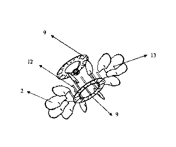
Figure 1 shows a schematic view of the high-speed dewatering and pulverizing
turbine (1) of the present invention.
Figure 2 shows a schematic view of the high-speed dewatering and pulverizing
turbine (1) of the present invention, with a view of the inner parts.
Figure 3 shows a schematic view of the dewatering and pulverizing turbine,
with
a view of the inner vanes or blades (2).
Figure 4 shows a schematic view of the turbine inner part (wheel or rotor)
containing the inner vanes or blades (2).
Figure 5 shows a schematic view of the turbine inner part (wheel or rotor)
containing the inner vanes or blades (2) with its parts broken down.
Figure 6 shows a top, side and bottom view of the turbine inner part
containing
the vanes or blades.
Figure 7 shows a schematic view of the turbine vane or blade with sinusoidal
upper edges (3).
Figure 8 shows a schematic view of the turbine vane or blade with triangular
upper edges (4).
Figure 9 shows a schematic view of the turbine vane or blade with polygonal
upper edges of five or more vertices (5).
Detailed Description of the Invention
The present invention is a high-speed dewatering and pulverizing turbine (1)
for
obtaining solid pulverized particles and dissociating the water present,
comprising
vanes or blades (2) especially designed to attain pulverization efficiently.
Additionally,
the present invention describes the procedure for breaking up solid particles
and
dissociating the water therein.
The high-speed dewatering and pulverizing turbine (1) must be mounted on a
drive system supportive of its central axis (11), which allows the turbine to
work at high
3630405

CA 03067884 2019-12-19
4
speed, thus breaking up the solid material particles and dissociating the
water within
the solid material. The turbine consists of the following elements:
- a stator (6) having circular geometry with a duct at one end (7) for the
output
of the solid pulverized particles;
- a duct in the bottom part of the turbine (10) for the input of the solid
particles to
be pulverized;
- a wheel or rotor (8) with vanes, located inside the stator, which
contains the
following elements:
- two vane fixing and mounting plates (9) of circular shape;
- a central axis (11) to fit the fixing plates (9);
- at least four separating and mounting bars (12) that run parallel to the
central axis (11) and attached perpendicularly through one of its ends to
the fixing and mounting plates (9); and
- at least four vanes (2) or blades that are joined to the central axis
(11)
and located radially, generally flat, where each vane (2) has a lower
inner slot (13) located at the bottom of one of its sides and close to the
turbine inlet;
- a central securing assembly for adjusting and securing all the elements
that
form the wheel or rotor (8).
The outer shape of the top of the vanes or blades (2) can be sinusoidal (3)
with
square teeth or with vertices, triangular (4) or polygonal (5) with five or
more vertices
(see Figures 7, 8 and 9, respectively). For example, vanes with vertices,
whose top or
tip is shaped as a half a polygon of eight or more sides, or vanes with a
sinusoidal-
shaped tip, can be present.
Each vane or blade (2), regardless of the top shape thereof, present following
the top two upper open-chute-type holes (14) at each side of the vane, and at
the
bottom, each vane presents a straight shape (15) on one of the sides thereof
(profile)
and a concave shape (16) on the other. Additionally, the same side that has
the
concave shape has the inner slot (13); see Figures 5, 7, 8 and 9. On the
straight (15)
and concave (16) form of the rotor (8) vanes, a resonance chamber, with
acoustic
amplitudes and frequencies that generate an ultrasound condition, with
measures
3630405

CA 03067884 2019-12-19
higher than 120 dB caused by the high speed and the sound as generated by the
inner
slot (13) due to the passage of air, is formed.
The rotor (8) can have 4, 6, 8, 10, 12, 16 or more pairs of vanes or blades
(2).
The vanes or blades are located along the turbine's housing or stator shape
keeping a
5 distance as defined around said housing (6).
The high-speed dewatering and pulverizing turbine (1) of the present invention
comprises in its drive system a double gear box to attain its high speed. The
rotational
speed preferably is in the range or comprised from about 2,000 RPM to about
10,000
RPM. Additionally, the pulverizing turbine can operate at room temperature or
at a set-
point temperature from about 30 C to about 100 C.
The top upper open-chute-type holes (14) at each side of the vanes (2) allow
as
the wheel or rotor rotates inside the stator for the free circulation of the
vanes inside the
stator (6) and a speed increase of the solid particles. On the other hand, the
tip
polygonal (5), triangular (4) or sinusoidal (3) shape of each rotor vane
allows to prevent
the material buildup in the stator (6) walls from stopping the equipment, i.e.
the turbine
friction or restraint caused by the material circulating inside the stator in
the space
between the fixed parts (stator walls) and the moving parts (wheel or rotor)
is
prevented. The brake "lining" effect with the circulating material is intended
to be
prevented; therefore, the vane top should be adjusted to the shape of the
stator fixed
.. parts, but with variations of the upper contour shape, such as square
teeth, waves,
vertices or any other shape that allows for the brake effect to be prevented.
The idea is
reducing the surface contour in relation to the fixed part contour, such as
the vane
envelope presents little shape variations in relation to the fixed part inner
envelope.
On the other hand, the lower inner slot (13) of the vanes or blades allows
them,
by rotating at determined speeds, to generate low-frequency signals and higher-
frequency harmonics to allow the material and the water particles inside the
turbine to
be atomized.
The procedure for breaking up the solid particles and dissociating the water
therein comprises:
a.- having a high-speed dewatering and pulverizing turbine (1) as previously
defined, and a drive system associated therewith;
3630405

CA 03067884 2019-12-19
6
b.- putting the drive system into operation for the turbine to attain the
required
high speed;
c.- inputting a current of air-borne solid particles under a condition of
negative
pressure or suction at the bottom (10) of the turbine (1); and
d.- pulverizing the solid particles and dissociating the water within the
solid
particles.
The current of air-borne solid particles enters the high-speed turbine (1) at
the
bottom (10) by suction or negative pressure. Once inside the turbine, the air-
borne
solid particles spin at high speed as a result of the rotation of the turbine
blades (2), as
a result of the lower inner slot (13) and as a result of the shape of the
rotor vanes. The
particles additionally recirculate at high speeds inside the turbine. The
recirculation is
caused by the proximity of the pressure and suction points in the design of
the high
speed turbine and housing (6). In order to facilitate the particle
recirculation inside the
turbine, the housing (6) from the circular end to the inlet (10) is designed
with conical
shape, the smaller diameter of said cone matching the diameter of the lower
fixing
plate (9) of the turbine rotor (8). The inner design of the high-speed turbine
and the
vanes within the rotor allows as the rotor rotates (8) for the material
circulating inside
the stator to pass through the space between the fixed parts (stator) and the
moving
parts (wheel or rotor); the vane or blade (2) moving part must be adjusted to
the stator
(6) fixed parts. In turn, the function of securing assembly is double since,
on the one
hand, it enables securing all the pieces or elements that form the rotor (8)
and, on the
other, it regulates the pressure of the fixing plates (9) on the vanes (2),
thus stretching
or shrinking them, and preventing the solid material buildup in the stator
inner surfaces.
Likewise, the polygonal, triangular or sinusoidal shape of the rotor (8) vanes
(2) allows
preventing the material buildup in the stator (6) walls from stopping the
equipment. As
passing through the interior of the turbine, the air-borne solid particles
exit it
transformed into air-borne solid particles with micro-dispersed air-borne
water.
The high-speed dewatering and pulverizing turbine has been designed to
simultaneously carry out the following physical principles:
= Generating negative pressure and axial and tangential offset of the input
material. Generating rubbing of the input material and breakup thereof.
3630405

CA 03067884 2019-12-19
7
= Generating microdispersion of the material dissociated water by
generating
ultrasound, which moves and displaces with the air.
= Generating air pressures higher than 400 mm. wc. (millimeters, water
column)
and travel speeds from about 40 m/s to about 90 m/s at the inlet (10).
= Causing low-frequency, high amplitude signals and secondary harmonics.
= Generating material compressions in its travel through the vanes.
= Generating the Bernoulli Effect that, through the vane lower inner slot
(13),
generates speed and pressure changes in different points of the turbine.
= Preventing through the vane design the material buildup in the turbine
walls.
= Keeping the inflow and outflow duct geometry, thus giving priority to the
material travel and the buildup in geometric discontinuities.
On the other hand, the adjustment of set-point temperatures is relevant to
each
material so as to prevent subjecting it to the glue (sticky) zone and allow
the free travel
(free flowing) condition of the material.
3630405

Representative Drawing
A single figure which represents the drawing illustrating the invention.
Administrative Status

2024-08-01:As part of the Next Generation Patents (NGP) transition, the Canadian Patents Database (CPD) now contains a more detailed Event History, which replicates the Event Log of our new back-office solution.

Please note that "Inactive:" events refers to events no longer in use in our new back-office solution.

For a clearer understanding of the status of the application/patent presented on this page, the site Disclaimer , as well as the definitions for Patent , Event History , Maintenance Fee  and Payment History  should be consulted.

Event History

Description Date
Deemed Abandoned - Failure to Respond to an Examiner's Requisition 2023-07-24
Examiner's Report 2023-03-23
Inactive: Report - No QC 2023-03-21
Letter Sent 2022-03-09
Request for Examination Received 2022-02-04
Request for Examination Requirements Determined Compliant 2022-02-04
All Requirements for Examination Determined Compliant 2022-02-04
Inactive: COVID 19 - Deadline extended 2020-06-10
Inactive: Cover page published 2020-02-05
Letter sent 2020-01-22
Application Received - PCT 2020-01-16
Inactive: IPC assigned 2020-01-16
Inactive: First IPC assigned 2020-01-16
National Entry Requirements Determined Compliant 2019-12-19
Application Published (Open to Public Inspection) 2018-12-27

Abandonment History

Abandonment Date Reason Reinstatement Date
2023-07-24

Maintenance Fee

The last payment was received on 2024-06-14

Note : If the full payment has not been received on or before the date indicated, a further fee may be required which may be one of the following

  • the reinstatement fee;
  • the late payment fee; or
  • additional fee to reverse deemed expiry.

Patent fees are adjusted on the 1st of January every year. The amounts above are the current amounts if received by December 31 of the current year.
Please refer to the CIPO Patent Fees web page to see all current fee amounts.

Fee History

Fee Type Anniversary Year Due Date Paid Date
MF (application, 2nd anniv.) - standard 02 2019-06-21 2019-12-19
Basic national fee - standard 2019-12-19 2019-12-19
MF (application, 3rd anniv.) - standard 03 2020-06-22 2020-06-18
MF (application, 4th anniv.) - standard 04 2021-06-21 2021-06-21
Request for examination - standard 2022-06-21 2022-02-04
MF (application, 5th anniv.) - standard 05 2022-06-21 2022-06-20
MF (application, 6th anniv.) - standard 06 2023-06-21 2023-06-19
MF (application, 7th anniv.) - standard 07 2024-06-21 2024-06-14
Owners on Record

Note: Records showing the ownership history in alphabetical order.

Current Owners on Record
BIODRYINGTECH SPA
EMPRESAS IANSA S.A.
Past Owners on Record
ROBERTO ENRIQUE ARAOS ALMENDRAS
Past Owners that do not appear in the "Owners on Record" listing will appear in other documentation within the application.
Documents

To view selected files, please enter reCAPTCHA code :


To view images, click a link in the Document Description column. To download the documents, select one or more checkboxes in the first column and then click the "Download Selected in PDF format (Zip Archive)" or the "Download Selected as Single PDF" button.

List of published and non-published patent-specific documents on the CPD .

If you have any difficulty accessing content, you can call the Client Service Centre at 1-866-997-1936 or send them an e-mail at CIPO Client Service Centre.


Document
Description 
Date
(yyyy-mm-dd) 
Number of pages   Size of Image (KB) 
Representative drawing 2023-12-11 1 7
Claims 2019-12-18 4 156
Description 2019-12-18 7 274
Drawings 2019-12-18 5 43
Abstract 2019-12-18 1 15
Representative drawing 2019-12-18 1 4
Maintenance fee payment 2024-06-13 2 56
Courtesy - Letter Acknowledging PCT National Phase Entry 2020-01-21 1 593
Courtesy - Acknowledgement of Request for Examination 2022-03-08 1 433
Courtesy - Abandonment Letter (R86(2)) 2023-10-02 1 562
International search report 2019-12-18 4 269
National entry request 2019-12-18 6 144
Declaration 2019-12-18 2 28
Amendment - Abstract 2019-12-18 2 82
Request for examination 2022-02-03 5 137
Examiner requisition 2023-03-22 4 202