Note: Descriptions are shown in the official language in which they were submitted.
CA 03068426 2019-12-23
WO 2019/005249 PCT/US2018/025508
VARIABLE ROTARY PENDULOUS MASS
VIBRATION SUPPRESSION SYSTEM
TECHNICAL FIELD
[0001] The present invention relates generally to the field of aircraft
vibration control
systems, and more particularly to a variable rotary mass vibration suppression
system.
BACKGROUND ART
[0002] Active counter-vibration devices have been used in rotary-wing
aircraft, such as
helicopters and tiltrotors, to oppose and cancel high levels of vibration
transmitted from the
rotor to the fuselage. If such vibrations are not suppressed, they can lead to
structural fatigue
and may be transmitted to other areas and systems of the helicopter.
[0003] Hub mounted vibration control systems are used to suppress vibrations
more
proximate to the source of the vibration, namely at the main rotor system. The
rotor system
of a conventional helicopter drives a plurality of rotor blades that are
subject to numerous
aerodynamic loads. Mast or hub mounted vibration isolation systems suppress
vibrations at a
location proximate to the source, as opposed to active vibration control
systems that may be
used to reduce or suppress vibrations at locations more remote from the main
rotor system.
[0004] U.S. Patent No. 8,920,125, entitled "Dual Frequency Hub Mounted
Vibration
Suppressor System," issued December 30, 2014, is directed to a hub mounted
vibration
suppression system that includes an annular electric motor system defined
about the axis of
rotation of the main rotor system and a control system in communication with
the annular
electric motor system to independently control rotation of at least two masses
about the axis
of rotation of the main rotor system to reduce in-plane vibration of the
rotating system. This
patent is also directed to a method of reducing vibrations in a rotary-wing
aircraft main rotor
system that includes independently rotating a multiple of independently
rotatable masses
disposed about the axis of rotation defined by the main rotor system and
controlling a relative
angular position of the independent rotatable masses to reduce the vibrations
of the main
rotor system.
[0005] U.S. Patent No. 8,435,002, entitled "Helicopter Vibration Control
System and
Rotating Assembly Rotary Forces Generators for Cancelling Vibrations," issued
May 7,
2013, is directed to a rotary blade rotating hub mounted rotating assembly
vibration control
system that includes a first imbalance mass concentration rotor, a second
imbalance mass
1
CA 03068426 2019-12-23
WO 2019/005249 PCT/US2018/025508
concentration rotor, a third imbalance mass concentration rotor, and a fourth
imbalance mass
concentration rotor, each having a center axis of rotation that is centered on
the rotating
assembly center axis of rotation.
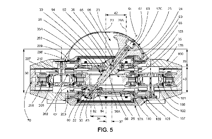
[0006] U.S. Patent Application Publication No. 2015/0203196, entitled "Active
Vibration
Control System With Non-Concentric Revolving Masses," is directed to vibration
control
system for a rotor hub having unbalanced weights each rotating about an axis
non-concentric
with the rotor hub axis.
BRIEF SUMMARY
[0007] With parenthetical reference to the corresponding parts, portions or
surfaces of the
disclosed embodiment, merely for purposes of illustration and not by way of
limitation, an
improved vibration suppression system (15, 215) for a rotary-wing aircraft
(16) having a
plurality of rotor blades (18) mounted to a rotor hub (19) and driven about a
central axis of
rotation (20, 220) at an operational speed and in a rotational direction (22)
relative to a non-
rotating body (21) of the aircraft is disclosed comprising: a vibration
control mass (23, 123,
223) having a center of mass (25, 125, 225); a first rotor (28, 128, 302)
having a first axis of
rotation coincident with the central axis; a second rotor (30, 130, 402)
having a second axis of
rotation coincident with the central axis; a first coupling (32, 132, 232)
between the first rotor
and the vibration control mass; the first coupling having a first coupling
center (33, 133, 233)
offset perpendicularly from the central axis a first radial coupling distance
(34, 234); a second
coupling (35, 135, 235) between the second rotor and the vibration control
mass; the second
coupling having a second coupling center (36, 136. 236) offset perpendicularly
from the
central axis a second radial coupling distance (37, 237); the first radial
coupling distance
being different from the second radial coupling distance; the first coupling
center offset
axially from the center of mass with respect to the central axis by a first
axial coupling
distance (38, 238); the second coupling center offset axially from the center
of mass with
respect to the central axis by a second axial coupling distance (39, 239); the
first axial
coupling distance being different from the second axial coupling distance; the
first and
second coupling centers having a selectively variable displacement angle (40)
defined by the
inclusive angle between a line (34A) extending between the central axis and
the first coupling
center and a line (37A) extending between the central axis and the second
coupling center;
wherein the first rotor and the second rotor are controllable to produce a
vibration control
force vector (41, 41A) having a controllable magnitude and frequency about the
central axis.
2
CA 03068426 2019-12-23
WO 2019/005249 PCT/US2018/025508
[0008] The first rotor and second rotor may be controllable to produce a
circular vibration
control force vector (41). The first rotor and second rotor may be
controllable to rotate in the
same direction (22) about the central axis to produce the circular vibration
control force
vector. The first rotor and second rotor may be controllable to produce a
linear vibration
control force vector (41A). The first rotor and second rotor may be
controllable to rotate in
opposite directions (22, 53) about the central axis to produce the linear
vibration control force
vector.
[0009] The center of mass may have a selectively variable radial displacement
distance (42)
from the central axis ranging from a minimum distance (FIG. 8) to a maximum
distance
(FIG. 6). When the displacement angle is zero degrees, the center of mass may
be coincident
to the central axis of rotation and the displacement distance may be the
minimum distance
from the central axis. The center of mass may be the maximum displacement
distance from
the central axis when the displacement angle is 180 degrees.
[0010] The first coupling center, the second coupling center and the center of
mass may align
on a common linkage axis (64, 164, 264) when the displacement angle is zero,
whereby a
sum of moments of the first coupling center about the central axis is equal
and opposite to a
sum of moments of the second coupling center about the central axis. The first
coupling
center may be offset axially from the second coupling center with respect to
the central axis
by a fixed distance (43, 243).
[0011] The vibration control mass may comprise a shaft (26, 126, 226)
elongated about a
shaft axis (64, 164, 264) and the shaft may be restrained (66, 68) from
movement axially
along the shaft axis relative to one of the first coupling center and the
second coupling center
and may be movable axially along the shaft axis relative to the other of the
first coupling
center and the second coupling center.
[0012] The vibration control force vector may be a function of a speed sum of
a rotational
speed of the hub about the central axis relative to the non-rotating body of
the aircraft and a
rotational speed of the center of mass about the central axis relative to the
hub. The first rotor
axis and the second rotor axis may be coincident with the central axis.
[0013] The vibration control mass may comprise a mass head (24, 124, 224) and
a mass shaft
(26, 126, 226) and the first coupling may be between the first rotor and the
mass shaft and the
second coupling may be between the second rotor and the mass shaft. The first
coupling may
comprise a first spherical bearing (32) having a first outer ring (80)
orientated about the first
coupling center (33) that rotates with rotation of the first rotor and a first
inner ring (83)
3
CA 03068426 2019-12-23
WO 2019/005249 PCT/US2018/025508
rotatable with the mass shaft in at least two degrees of motion about the
first coupling center
relative to the first outer ring. The second coupling may comprise a second
spherical bearing
(35) having a second outer ring (90) orientated about the second coupling
center (36) that
rotates with rotation of the second rotor and a second inner ring (93)
rotatable with the mass
shaft in at least two degrees of motion about the second coupling center
relative to the second
outer ring. The first outer ring may comprise a first annular bore having a
first bore axis
(33A); the first bore axis may be not concentric with the central axis; the
first coupling center
may be concentric with the first bore axis; the mass shaft may extend through
the first annular
bore; the second outer ring may comprise a second annular bore having a second
bore axis
(36A); the second bore axis may be not concentric with the central axis; the
second coupling
center may be concentric with the second bore axis; and the mass shaft may
extend through
the second annular bore. The mass shaft may be elongated about a shaft axis
(64)
intersecting the first coupling center; the mass shaft may be fixed to the
first inner ring,
whereby the first inner ring rotates about the first coupling center with
rotation of the mass
shaft about the shaft axis and the mass shaft may be restrained from movement
axially along
the shaft axis relative to the first inner ring; and the mass shaft may be in
sliding engagement
with the second inner ring, whereby the mass shaft may be movable axially
along the shaft
axis relative to the second inner ring and the mass shaft may be rotatable
about the shaft axis
relative to the second inner ring.
[0014] The first coupling (132) may comprise a universal type coupling having:
a first yoke
(180) that rotates with rotation of the first rotor (128); a second yoke (181)
having a first
pivot shaft (183B) rotationally supported by the first yoke about a first
pivot axis (133B); a
bearing (185) between the first pivot shaft and the first yoke; a second pivot
shaft (183A)
connected to the mass shaft (126) and rotationally supported by the second
yoke about a
second pivot axis (133A); and a bearing (184) between the second pivot shaft
and the second
yoke. The second coupling (135) may comprise a universal type coupling having:
a third
yoke (190) that rotates with rotation of the second rotor (130); a fourth yoke
(191) having a
third pivot shaft (193B) rotationally supported by the third yoke about a
third pivot axis
(136B); a bearing (195) between the third pivot shaft and the third yoke; a
fourth pivot shaft
(193A) connected to the mass shaft and rotationally supported by the fourth
yoke about a
fourth pivot axis (136A); and a bearing (194) between the fourth pivot shaft
and the fourth
yoke. The first coupling center may comprise an intersection of the first
pivot axis and the
4
CA 03068426 2019-12-23
WO 2019/005249 PCT/US2018/025508
second pivot axis and the second coupling center may comprise an intersection
of the third
pivot axis and the fourth pivot axis.
[0015] The vibration suppression system may comprise: a first motor (100, 300)
driven to
rotate the first rotor about the central axis; a second motor (200, 400)
driven to rotate the
second rotor about the central axis; and a controller (70, 270) that receives
input signals and
outputs command signals to the first motor and the second motor to control the
speed of
rotation (o)1) of the first coupling center about the central axis, the speed
of rotation (o)1) of
the second coupling center about the central axis, and the displacement angle.
The controller
may vary the displacement angle to vary the operational magnitude of the
vibration control
force vector. The displacement angle may be variable from 0 degrees to 360
degrees. The
controller may maintain a constant displacement angle to maintain a desired
constant
operational magnitude of the vibration control force vector circularly about
the central axis.
The controller may selectively control the first motor and the second motor
such that the first
coupling center rotates about the central axis at a first rotational speed and
the second
coupling center rotates about the central axis at a second rotational speed,
whereby the
controller controls a speed differential between the speeds of rotation of the
first and second
coupling centers about the central axis. The controller may vary the
displacement angle by
varying the speed differential from substantially 1 to 1. The controller may
vary the
operational magnitude of the vibration control force vector by varying the
speed differential
such that the first rotational speed that the first coupling center rotates
about the central axis
is different from the second rotational speed that the second coupling center
rotates about the
central axis. The controller may maintain the operational magnitude of the
vibration control
force vector at a constant by maintaining the speed differential at
substantially 1 to 1.
[0016] The vibration suppression system may comprise: a unit frame (217); the
first motor
(300) having a stator mounted to the unit frame; the first rotor (302) having
an annular stator-
facing rim (311) and a plurality of magnets (306) supported by the annular
stator-facing rim;
the second motor (400) having a stator (401) mounted to the unit frame; and
the second rotor
(402) having an annular stator-facing rim (411) and a plurality of magnets
(406) supported by
the annular stator-facing rim.
[0017] The vibration suppression system may comprise: a unit frame 17; the
first motor (100)
having a first stator (102) mounted to the unit frame and a first output shaft
(107) rotatable
about a first motor axis (103) relative to the first stator; a first
rotational coupling (104)
between the output shaft of the first motor and the first rotor; the second
motor (200) having a
CA 03068426 2019-12-23
WO 2019/005249 PCT/US2018/025508
second stator (101) mounted to the unit frame and a second output shaft (207)
rotatable about
a second motor axis (203) relative to the second stator; and a second
rotational coupling (204)
between the second output shaft of the second motor and the second rotor. The
first
rotational coupling may comprise a first output gear (108) connected to the
first output shaft
and a first ring gear (109) connected to the first rotor, the first ring gear
in meshed
engagement with the first output gear; and the second rotational coupling may
comprise a
second output gear (208) connected to the second output shaft and a second
ring gear (209)
connected to the second rotor, the second ring gear in meshed engagement with
the second
output gear.
[0018] The vibration suppression system may comprise a sensor (71) for
measuring vibration
and providing the input signals to the controller. The first motor and the
second motor may
each comprise a rotary electric motor. One of the first or second motors may
be controlled to
operate in a regeneration mode and the other of the first or second motors may
be controlled
to operate in a power generation mode.
[0019] The vibration suppression system may comprise a vibration control
housing (17, 217)
adapted to be mounted to the rotor hub (19) and operationally configured to
rotate with the
rotor hub (19) about the hub axis (20, 220) in the operational rotational
direction of the rotor
hub. The housing may comprise a base (117A) fixed to the hub, an outer ring
(117B), an
inside ring (117C) and a cap (117D).
[0020] The first rotor may be rotationally supported by a first bearing set
(110, 305) acting
between the housing and the first rotor and the second rotor may be
rotationally supported by
a second bearing set (210, 405) acting between the second rotor and the
housing. The
controller may be supported by and rotate with the vibration control housing.
The vibration
suppression system may further comprise a slip ring configured to provide
input signals to the
controller.
[0021] In another aspect, a vibration suppression system is disclosed
comprising: a vibration
control mass having a center of mass; a first rotor having a central axis of
rotation; a second
rotor having an axis of rotation coincident with the central axis of rotation;
a first coupling
between the first rotor and the vibration control mass; the first coupling
having a first
coupling center offset perpendicularly from the central axis of rotation a
first radial coupling
distance; a second coupling between the second rotor and the vibration control
mass; the
second coupling having a second coupling center offset perpendicularly from
the central axis
of rotation a second radial coupling distance; the first radial coupling
distance being different
6
CA 03068426 2019-12-23
WO 2019/005249 PCT/US2018/025508
from the second radial coupling distance; the first coupling center offset
axially from the
center of mass with respect to the central axis of rotation by a first axial
coupling distance;
the second coupling center offset axially from the center of mass with respect
to the central
axis of rotation by a second axial coupling distance; the first axial coupling
distance being
different from the second axial coupling distance; the first and second
coupling centers
having a selectively variable displacement angle defined by the inclusive
angle between a
line extending between the central axis of rotation and the first coupling
center and a line
extending between the central axis of rotation and the second coupling center;
wherein the
first rotor and the second rotor are controllable to produce a vibration
control force vector
having a controllable magnitude and frequency about the central axis of
rotation.
[0022] The first rotor and second rotor may be controllable to produce a
circular vibration
control force vector or a linear vibration control force vector.
[0023] The center of mass may have a selectively variable radial displacement
distance from
the central axis of rotation ranging from a minimum distance to a maximum
distance; when
the displacement angle is zero degrees, the center of mass may be coincident
to the central
axis of rotation and the displacement distance may be the minimum distance
from the central
axis of rotation; and the center of mass may be the maximum displacement
distance from the
central axis of rotation when the displacement angle is 180 degrees.
[0024] The vibration control mass may comprise a mass head and a mass shaft
and the first
coupling may be between the first rotor and the mass shaft and the second
coupling may be
between the second rotor and the mass shaft. The first coupling may comprise a
first
spherical bearing having a first outer ring orientated about the first
coupling center that
rotates with rotation of the first rotor and a first inner ring rotatable with
the mass shaft in at
least two degrees of motion about the first coupling center relative to the
first outer ring; and
the second coupling may comprise a second spherical bearing having a second
outer ring
orientated about the second coupling center that rotates with rotation of the
second rotor and
a second inner ring rotatable with the mass shaft in at least two degrees of
motion about the
second coupling center relative to the second outer ring.
[0025] The first coupling may comprise a universal type coupling having a
first yoke that
rotates with rotation of the first rotor, a second yoke having a first pivot
shaft rotationally
supported by the first yoke about a first pivot axis, a bearing between the
first pivot shaft and
the first yoke, a second pivot shaft connected to the mass shaft and
rotationally supported by
the second yoke about a second pivot axis, and a bearing between the second
pivot shaft and
7
CA 03068426 2019-12-23
WO 2019/005249 PCT/US2018/025508
the second yoke. The second coupling may comprise a universal type coupling
having a third
yoke that rotates with rotation of the second rotor, a fourth yoke having a
third pivot shaft
rotationally supported by the third yoke about a third pivot axis, a bearing
between the third
pivot shaft and the third yoke, a fourth pivot shaft connected to the mass
shaft and
rotationally supported by the fourth yoke about a fourth pivot axis, and a
bearing between the
fourth pivot shaft and the fourth yoke. The first coupling center may comprise
an intersection
of the first pivot axis and the second pivot axis and the second coupling
center may comprise
an intersection of the third pivot axis and the fourth pivot axis.
[0026] The vibration suppression system may comprise: a first motor driven to
rotate the first
rotor about the central axis of rotation; a second motor driven to rotate the
second rotor about
the central axis of rotation; and a controller that receives input signals and
outputs command
signals to the first motor and the second motor to control the speed of
rotation of the first
coupling center about the central axis of rotation, the speed of rotation of
the second coupling
center about the central axis of rotation, and the displacement angle.
[0027] The controller may vary the displacement angle to vary the operational
magnitude of
the vibration control force vector and the controller may maintain a constant
displacement
angle to maintain a desired constant operational magnitude of the vibration
control force
vector circularly about the central axis of rotation. The controller may
selectively control the
first motor and the second motor such that the first coupling center rotates
about the central
axis of rotation at a first rotational speed and the second coupling center
rotates about the
central axis of rotation at a second rotational speed, whereby the controller
controls a speed
differential between the speeds of rotation of the first and second coupling
centers about the
central axis of rotation; the controller may vary the displacement angle by
varying the speed
differential from substantially 1 to 1; the controller may vary the
operational magnitude of the
vibration control force vector by varying the speed differential such that the
first rotational
speed that the first coupling center rotates about the central axis of
rotation is different from
the second rotational speed that the second coupling center rotates about the
central axis of
rotation; and the controller may maintain the operational magnitude of the
vibration control
force vector at a constant by maintaining the speed differential at
substantially 1 to 1. The
vibration suppression system may comprise a sensor for measuring vibration and
providing
the input signals to the controller.
[0028] The vibration suppression system may comprise: a unit frame; the first
motor having a
stator mounted to the unit frame; the first rotor having an annular stator-
facing rim and a
8
CA 03068426 2019-12-23
WO 2019/005249 PCT/US2018/025508
plurality of magnets supported by the annular stator-facing rim; the second
motor having a
stator mounted to the unit frame; and the second rotor having an annular
stator-facing rim and
a plurality of magnets supported by the annular stator-facing rim.
[0029] The vibration suppression system may comprise: a unit frame; the first
motor having a
first stator mounted to the unit frame and a first output shaft rotatable
about a first motor axis
relative to the first stator; a first rotational coupling between the output
shaft of the first motor
and the first rotor; the second motor having a second stator mounted to the
unit frame and a
second output shaft rotatable about a second motor axis relative to the second
stator; and a
second rotational coupling between the second output shaft of the second motor
and the
second rotor. The first rotational coupling may comprise a first output gear
connected to the
first output shaft and a first ring gear connected to the first rotor, the
first ring gear in meshed
engagement with the first output gear; and the second rotational coupling may
comprise a
second output gear connected to the second output shaft and a second ring gear
connected to
the second rotor, the second ring gear in meshed engagement with the second
output gear.
BRIEF DESCRIPTION OF THE DRAWINGS
[0030] FIG. 1 is a representative perspective view of an embodiment of the
improved
vibration suppression system on a rotor hub assembly of a rotary wing
aircraft.
[0031] FIG. 2 is an enlarged partial cutaway perspective view of the rotor hub
assembly
shown in FIG. 1.
[0032] FIG. 3 is an enlarged perspective view of the rotor hub assembly shown
in FIG. 2.
[0033] FIG. 4 is an enlarged perspective view of the vibration suppression
unit shown in FIG.
3.
[0034] FIG. 5 is a rear vertical cross-sectional view of the vibration
suppression unit shown
in FIG. 4, taken generally on line A-A of FIG. 4.
[0035] FIG. 6 is a partial perspective view of the vibration suppression unit
shown in FIG. 4
in a maximum resulting force configuration.
[0036] FIG. 6A is a top partial cutaway view of the vibration suppression unit
shown in FIG.
6 in the maximum resulting force configuration.
[0037] FIG. 6B is a right side view of the vibration suppression unit shown in
FIG. 6 in the
maximum resulting force configuration.
9
CA 03068426 2019-12-23
WO 2019/005249 PCT/US2018/025508
[0038] FIG. 6C is a top diagram view of the operational movement and generated
counter
vibration forces of the vibration suppression unit shown in FIG. 6 in a
circular operation
mode and in the maximum resulting force configuration.
[0039] FIG. 7 is a partial perspective view of the vibration suppression unit
shown in FIG. 4
in an intermediate resulting force configuration.
[0040] FIG. 7A is a top partial cutaway view of the vibration suppression unit
shown in FIG.
7 in the intermediate resulting force configuration.
[0041] FIG. 7B is a right side view of the vibration suppression unit shown in
FIG. 7 in the
intermediate resulting force configuration.
[0042] FIG. 7C is a top diagram view of the operational movement and generated
counter
vibration forces of the vibration suppression unit shown in FIG. 7 in a
circular operation
mode and in the intermediate resulting force configuration.
[0043] FIG. 8 is a partial perspective view of the vibration suppression unit
shown in FIG. 4
in a minimum resulting force configuration.
[0044] FIG. 8A is a top partial cutaway view of the vibration suppression unit
shown in FIG.
8 in the minimum resulting force configuration.
[0045] FIG. 8B is a right side view of the vibration suppression unit shown in
FIG. 8 in the
minimum resulting force configuration.
[0046] FIG. 8C is a top diagram view of the operational movement and generated
counter
vibration forces of the vibration suppression unit shown in FIG. 8 in a
circular operation
mode and in the minimum resulting force configuration.
[0047] FIG. 9 is a partial perspective view of the vibration suppression unit
shown in FIG. 4
in the minimum resulting force configuration.
[0048] FIG. 9A is a partial perspective view of the vibration suppression unit
shown in FIG.
9 in the maximum resulting force configuration.
[0049] FIG. 9B is a side diagram view showing the dimensional relationships of
the vibration
suppression mass shown in FIG. 9 in the minimum resulting force configuration
together with
the dimensional relationships of the vibration suppression mass shown in FIG.
9A in the
maximum resulting force configuration.
[0050] FIG. 9C is a diagram of the operation forces of the vibration
suppression mass shown
in FIG. 7 in the intermediate resulting force configuration.
[0051] FIG. 10 shows the x and y components of a circular reaction force
versus time for a
given constant force magnitude.
CA 03068426 2019-12-23
WO 2019/005249 PCT/US2018/025508
[0052] FIG. 10A shows the x and y components of a circular reaction force
versus time for
the maximum, intermediate and minimum configurations shown in FIGS. 6, 7 and
8,
respectively.
[0053] FIGS. 11A-11D show the relative positions of the mass for the curve of
the maximum
configuration shown in FIG. 10A.
[0054] FIGS. 12A-12D show the relative positions of the mass for the curve of
the
intermediate configuration shown in FIG. 10A.
[0055] FIGS. 13A-13D show the relative positions of the mass for the curve of
the minimum
configuration shown in FIG. 10A.
[0056] FIG. 14 is a schematic diagram of the vibration controller system for
the vibration
suppression unit shown in FIG. 1.
[0057] FIG. 14A is a detailed schematic diagram of the vibration power system
for the
vibration suppression unit shown in FIG. 1.
[0058] FIG. 15 is a diagram of the operational movement of the vibration
suppression unit
shown in FIG. 4 in a linear operational mode.
[0059] FIG. 16 is a perspective view of an alternative embodiment of the
rotors and mass
couplings shown in FIG. 4.
[0060] FIG. 17 is a longitudinal cross-sectional view of the rotors and mass
couplings shown
in FIG. 16, taken generally on line B-B of FIG. 16.
[0061] FIG. 17A is a transverse cross-sectional view of the top rotor and mass
coupling
shown in FIG. 17, taken generally on line C-C of FIG. 17.
[0062] FIG. 17B is a transverse cross-sectional view of the bottom rotor and
mass coupling
shown in FIG. 17, taken generally on line D-D of FIG. 17.
[0063] FIG. 18 is a vertical cross-sectional view of an alternative direct
drive embodiment of
the vibration suppression unit shown in FIG. 5.
DETAILED DESCRIPTION OF THE EMBODIMENTS
[0064] At the outset, it should be clearly understood that like reference
numerals are intended
to identify the same structural elements, portions or surfaces consistently
throughout the
several drawing figures, as such elements, portions or surfaces may be further
described or
explained by the entire written specification, of which this detailed
description is an integral
part. Unless otherwise indicated, the drawings are intended to be read (e.g.,
crosshatching,
arrangement of parts, proportion, degree, etc.) together with the
specification, and are to be
11
CA 03068426 2019-12-23
WO 2019/005249 PCT/US2018/025508
considered a portion of the entire written description. As used in the
following description,
the terms "horizontal", "vertical", "left", "right", "up" and "down", as well
as adjectival and
adverbial derivatives thereof (e.g., "horizontally", "rightwardly",
"upwardly", etc.), simply
refer to the orientation of the illustrated structure as the particular
drawing figure faces the
reader. Similarly, the terms "inwardly" and "outwardly" generally refer to the
orientation of a
surface relative to its axis of elongation, or axis of rotation, as
appropriate.
[0065] FIG. 1 is a schematic illustration of helicopter 16 having airframe 21
and main rotor
system 50 that is driven about center axis of rotation 20. Main rotor system
50 includes a
plurality of rotor blades 18 mounted to rotor hub 19 via rotor blade grips 51.
Rotor hub 19 is
driven about center axis of rotation 20 by main rotor shaft 52, which is
driven through a main
rotor gear box by one of more aircraft engines. Main rotor shaft 52 and hub 19
rotate in
rotational direction 22 at an operational rotational frequency about center
axis of rotation 20.
Although a helicopter is shown and described in this embodiment, vibration
suppression unit
15 may be used with other types or configurations of rotary-wing aircraft or
rotor-craft or in
other vibration control applications.
[0066] As shown in FIGS. 1-3, vibration suppression unit 15 is mounted on top
of rotor hub
19. FIG. 1 provides a frame of reference comprising longitudinal axis x-x
aligned with the
longitudinal axis of helicopter 16, transverse axis y-y perpendicular to axis
x-x, and vertical
axis z-z concentric with center axis of rotation 20 of rotor hub 19. While
system 15 is shown
being mounted above hub 19, as an alternative a vibration suppression unit may
be mounted
directly to fuselage 21 of helicopter 16.
[0067] As shown in FIGS. 1-5, vibration suppression unit 15 is mounted to hub
19 and
generally includes mass 23 having mass head 24 and mass shaft 26, first motor
100
rotationally coupled via drive train 104 to mass shaft 26 at first spherical
bearing 32, second
motor 200 rotationally coupled via drive train 204 to mass shaft 26 at second
spherical
bearing 35, and controller 70, all supported within unit housing 17 mounted to
hub 19.
[0068] Unit housing 17 comprises cylindrical base 17A, orientated coaxially on
hub 19 about
center axis 20, outer cylindrical support frame 17B extending upward from base
17A and
orientated coaxially with hub 19 about center axis 20, and upper dome 17C
covering
assembly 15.
[0069] As shown in FIGS. 4 and 5, housing 17 supports first motor 100 and
second motor
200. Motor 100 comprises stator 101, fixed to frame 17, and rotor 102 that
rotates about axis
103 relative to stator 101. Upper and lower bearings 105 act between rotor 102
and housing
12
CA 03068426 2019-12-23
WO 2019/005249 PCT/US2018/025508
17 such that rotor 102 is rotatable about axis 103 relative to housing 17. In
this embodiment,
motor 100 is a rotary brushless permanent magnet electric motor with rotor 102
having
permanent magnets 106 and stator 101 having coils energized to drive rotor 102
about axis
103 in either rotational direction 22 or 53.
[0070] Motor 200 comprises stator 201, fixed to frame 17, and rotor 202 that
rotates about an
axis 205 relative to stator 201. Upper and lower bearings 205 act between
rotor 202 and
housing 17 such that rotor 202 is rotatable about axis 203 relative to housing
17. In this
embodiment, motor 200 is a rotary brushless permanent magnet electric motor
with rotor 202
having permanent magnets 206 and stator 201 having coils energized to drive
rotor 202 about
axis 205 in either rotational direction 22 or 53.
[0071] In this embodiment, motor axis 105, motor axis 205 and central axis 20
are parallel to
each other, but are not coaxial. Shaft 107 extends from rotor 102 and
terminates at output
gear 108 having externally facing teeth. Gear 108 is in meshed engagement with
the
outwardly facing teeth of ring gear 109 fixed to direct rotor 28. Ring gear
109 is a ring-
shaped annular structure orientated about center axis 20. Ring gear 109 and
direct rotor 28
rotate about center axis 20 relative to housing 17 with rotation of rotor 102
and gear 108
about motor axis 103. Direct rotor 28 rotates about axis 20 opposite to the
direction of
rotation of rotor 102 and gear 108 about axis 103. However, other gearing
configurations
may be used as alternatives to drive direct rotor 28 about axis 20 relative to
hub 19. In a
circular force mode, first motor 100 is configured to rotate direct rotor 28
about center axis
20 relative to rotor shaft 28 and hub 19 in a rotational direction that is the
same as rotational
direction 22 of hub 19 and at a desire operational frequency or speed of
rotation. Thus, rotor
102 is selectively driven about axis 103 in rotational direction 53 to drive
rotation of direct
rotor 28 about center axis 20 in rotational direction 22.
[0072] Shaft 207 extends from rotor 202 and terminates at output gear 208
having externally
facing teeth. Gear 208 is in meshed engagement with the outwardly facing teeth
of ring gear
209 fixed to direct rotor 30. Ring gear 209 is a ring-shaped annular structure
orientated about
center axis 20. Ring gear 209 and direct rotor 30 rotate about center axis 20
relative to
housing 17 with rotation of rotor 202 and gear 208 about motor axis 203.
Direct rotor 30
rotates about axis 20 opposite to the direction of rotation of rotor 202 and
gear 208 about axis
203. However, other gearing configurations may be used as alternatives to
drive direct rotor
30 about axis 20 relative to hub 19. In a circular force mode, second motor
200 is configured
to rotate direct rotor 30 about center axis 20 relative to rotor shaft 28 and
hub 19 in a
13
CA 03068426 2019-12-23
WO 2019/005249 PCT/US2018/025508
rotational direction that is the same as rotational direction 22 of hub 19 and
at a desired
operational frequency or speed of rotation. Thus, rotor 202 is selectively
driven about axis
203 in rotational direction 53 to drive rotation of direct rotor 30 about
center axis 20 in
rotational direction 22.
[0073] As shown in FIGS. 4 and 5, direct rotor 28 is rotationally supported by
housing 17.
Upper and lower bearing pairs 110 act between the inner cylindrical bearing
surfaces of
frame 17 and the opposed outer cylindrical bearing surfaces of direct rotor
28, respectively.
Direct rotor 28 is configured to rotate about axis 20 on upper and lower
bearing pairs 110.
Thus, direct rotor 28 is mounted on housing 17 by rolling bearings 110 such
that direct rotor
28 is rotatable relative to housing 17. Direct rotor 28 has a center of mass
or gravity that is
substantially coincident with axis 20 about which it rotates.
[0074] As shown in FIGS. 4 and 5, direct rotor 30 is rotationally supported by
housing 17.
Upper and lower bearing pairs 210 act between the inner cylindrical bearing
surfaces of
frame 17 and the opposed outer cylindrical bearing surfaces of direct rotor
30, respectively.
Direct rotor 30 is configured to rotate about axis 20 on upper and lower
bearing pairs 210.
Thus, direct rotor 30 is mounted on housing 17 by rolling bearings 210 such
that direct rotor
30 is rotatable relative to housing 17. Direct rotor 30 has a center of mass
or gravity that is
substantially coincident with axis 20 about which it rotates.
[0075] In this embodiment, mass 23 comprises a generally mushroom shaped mass
head 24
fixed to first threaded end portion 61 of shaft 26 by nut 63. Shaft 26 is a
generally cylindrical
sold member orientated about mass link axis 64 such that mass 23 is generally
symmetrical
about mass link axis 64 and has a center of mass or center of gravity 25 on
shaft axis 64.
Mass 23 is rotationally supported at spherical bearing 32 having coupling
center 33 by direct
rotor 28. Mass 23 is also rotationally supported at spherical bearing 35
having coupling
center 36 by direct rotor 30.
[0076] In this embodiment, spherical bearing 32 is a rotary coupling about
center 33 between
shaft 26 of mass 23 and direct rotor 28. As shown, direct rotor 28 is fixed
via bolts 81 to
outer race or ring 80 orientated about coupling center 33 such that ring 80
rotates with
rotation of direct rotor 28. Ring 80 has an inner bore and spherical inner
diameter surface 82
and is orientated about bore axis 33A. The second end portion 62 of shaft 26,
opposite to
first end portion 61 and mass head 24, extends through and is attached to ball
83 having outer
spherical diameter surface 84. Ball 83 is retained in outer ring 80, with
surface 84 of ball 83
in sliding engagement with surface 82 of outer ring 80. Thus, outer ring 80
rotates with
14
CA 03068426 2019-12-23
WO 2019/005249 PCT/US2018/025508
rotation of first direct rotor 28, and ball 83 is rotatable with mass shaft 26
in at least two
degrees of motion about first coupling center 33 relative to outer ring 80.
[0077] In this embodiment, spherical bearing 35 is a rotary coupling about
center 36 between
shaft 26 of mass 23 and direct rotor 30. As shown, direct rotor 30 is clamped
via bolts 91 to
outer race or ring 90 orientated about coupling center 36 such that ring 90
rotates with
rotation of second direct rotor 30. Ring 90 has an inner bore and spherical
inner diameter
surface 92 and is orientated about bore axis 36A. The medial portion 65 of
shaft 26, between
first end portion 61 and mass head 24 and second end portion 62 and ball 83,
extends through
and is attached to ball 93 having outer spherical diameter surface 94. Ball 93
is retained in
outer ring 90, with surface 94 of ball 93 in sliding engagement with surface
92 of outer ring
90. Thus, outer ring 90 rotates with rotation of second direct rotor 30, and
ball 93 is rotatable
with mass shaft 26 in at least two degrees of motion about second coupling
center 36 relative
to outer ring 90.
[0078] Shaft 26 is restrained from movement axially in the through-bore of
ball 93 along
shaft axis 64 relative to ball 93 by annular step 66 in shaft 26 on one side
and annular rim 68
of mass head 24 on the other side, such that shaft 26 does not move axially in
either direction
along shaft axis 64 relative to coupling center 36. However, end portion 62 of
shaft 26 is not
restrained in such a manner. Shaft end portion 62 may slide in the through-
bore of ball 83,
and shaft 26 is in sliding engagement with ball 83 such that shaft 26 is
movable axially along
shaft axis 64 relative to ball 83 and coupling center 33, and shaft 26 is
rotatable about shaft
axis 64 relative to ball 83 and coupling center 33.
[0079] As shown in FIGS. 4-6 and 9-9C, ring 80 is not concentric with direct
rotor 28 about
rotor axis of rotation 20 (al). Rather, ring 80 is offset in rotor 28 such
that coupling center
33 (p2) is offset perpendicularly from central axis 20 (al) by first radial
coupling distance 34
(r2). Similarly, ring 90 is not concentric with direct rotor 30 about rotor
axis of rotation 20
(al). Rather, ring 90 is offset in rotor 30 such that coupling center 36 (pl)
is offset
perpendicularly from central axis 20 (al) by second radial coupling distance
37 (r1). As
shown, first radial coupling distance 34 is different from second radial
coupling distance 37.
In this embodiment, first radial coupling distance 34 is about twice second
radial coupling
distance 37.
[0080] As also shown, mass head 24 and center of mass 25, rotor 30, and rotor
28 are stacked
axially relative to center axis 20 such that coupling center 33 (p2) is offset
axially from center
of mass 25 with respect to central axis 20 (al) by a first axial coupling
distance 38 (h1 + h2).
CA 03068426 2019-12-23
WO 2019/005249 PCT/US2018/025508
Second coupling center 36 is in turn offset axially from center of mass 25
with respect to
central axis 20 by a second axial coupling distance 39 (h1). Accordingly,
first coupling
center 33 is offset axially from second coupling center 36 with respect to
central axis 20 by
coupling distance 43 (h2). As shown, first axial coupling distance 38 is
different from second
axial coupling distance 39. In this embodiment, first axial coupling distance
38 is greater
than second axial coupling distance 39.
[0081] As shown in FIG. 3, based on radial displacement distance 34 of
coupling center 33
from axis 20 and radial displacement distance 37 of coupling center 36 from
central axis 20,
center of mass 25 has a selectively variable radial displacement distance 42
(d) from central
axis 20 ranging from a minimum distance (d = 0), as shown in FIGS. 8-8C and 9,
to a
maximum distance (d max), as shown in FIGS. 6-6C and 9A.
[0082] As shown in FIGS. 6A, 6C, 7A, 7C, 8A, 8C and 9C, ring 80 and first
coupling center
33, and ring 90 and second coupling center 36, have a selectively variable
displacement angle
40 (A< (pi, p2)) about center axis 20 defined by the inclusive angle between a
phantom or
imaginary line 34A, extending between central axis 20 and first coupling
center 33
perpendicular to central axis 20, and a phantom or imaginary line 37A
extending between
central axis 20 and second coupling center 36 perpendicular to central axis
20. As shown, the
magnitude of radial displacement distance 42 (d) of center of mass 25 from
central axis 20,
between a minimum distance (d = 0) and a maximum distance (d max), is
selectively varied
by selectively varying displacement angle 40 between zero degrees and 180
degrees,
respectively. As shown, the relative rotation of rotors 28 and 30 may be
controlled to vary
displacement angle 40, and thereby vary displacement distance 42 (d), to
produce a vibration
control force vector 41 having a controllable magnitude and frequency about
central axis 20.
[0083] Thus, first coupling center 33 (p2) is driven about center axis 20 (al)
via rotor 28 in a
circular path of radius 34 (r2). Rotor 28 is selectively driven by motor 100
and output gear
108 in rotational direction 22 at a rotational frequency (col). Thus, rotation
of rotor 102 and
output gear 108 about axis 103 causes rotation of rotor 28 and first coupling
center 33 about
axis 20. Second coupling center 36 (p1) is driven about center axis 20 (al)
via rotor 30 in a
circular path of diameter 37 (r1). Rotor 30 is selectively driven by motor 200
and output gear
208 in rotational direction 22 at a rotational frequency (w2). Thus, rotation
of rotor 202 and
output gear 208 about axis 203 causes rotation of rotor 30 and first coupling
center 36 about
axis 20. Accordingly, first coupling center 33 and second coupling center 36
may be
selectively driven to rotate about axis 20 at the same time. When first
coupling center 33 and
16
CA 03068426 2019-12-23
WO 2019/005249 PCT/US2018/025508
second coupling center 36 are driven to rotate about axis 20 at the same speed
(col = (02),
displacement angle 40, and thereby displacement distance 42 (d), are
maintained at a
constant. To vary displacement angle 40, and thereby vary displacement
distance 42 (d) to
produce a desired vibration control force vector 41, first coupling center 33
and second
coupling center 36 are driven to rotate about axis 20 at different speeds (col
(02) until the
desired displacement distance 42 (d) and magnitude of vibration control force
vector 41 is
achieved. The relative positions of first coupling center 33 and second
coupling center 36 to
each other about center axis 20 is controlled to control distance 42 of center
of mass 25 from
central axis 20. In this embodiment, such distance can range from a maximum
eccentric
distance (d max) when displacement angle 40 is 180 degrees, such that first
coupling center
33 and second coupling center 36 are the furthest from each other about
central axis 20, as
shown in FIGS. 6-6C, to a minimum eccentric distance (d= 0) when displacement
angle 40 is
about zero degrees, such that first coupling center 33 and second coupling
center 36 are
angularly aligned about central axis 20, and center of mass 25 is on central
axis 20, as shown
in FIGS. 8-8C.
[0084] First coupling center 33 is offset a radial distance 34 from axis 20.
Accordingly, rotor
28 is rotationally coupled to mass 23 such that first coupling center 33, and
shaft 26 at end
portion 62, rotates about axis 20 with selective rotation of drive gear 108
about axis 103.
Second coupling center 36 is offset a radial distance 37 from axis 20.
Accordingly, rotor 30
is also rotationally coupled to mass 23 such that second coupling center 36,
and shaft 26 at
intermediate portion 65, rotates about axis 20 with selective rotation of
drive gear 208 about
axis 203. Thus, first and second coupling centers 33 and 36 have a selectively
variable
displacement angle 40 defined by the inclusive angle between line 34A
extending between
axis 20 and first coupling center 33 and line 37A extending between axis 20
and second
coupling center 36 when superimposed on the same plane perpendicular to axis
20.
[0085] As shown in FIGS. 6C, 7C, 8C and 9C, mass 23 may be controlled via
motors 100
and 200 and rotors 28 and 30 to rotate center of mass 25 of mass 23 about axis
20 at a desired
rotational frequency (w), which rotation results in a circular vibration
control force 41.
Furthermore, the magnitude of force 41 may be varied by varying angle 40,
which varies
distance 42 (d) of center of mass 25 from its center of rotation 20. Since
rotors 28 and 30
may be rotated at different speeds to vary angle 40 and distance 42 (d), the
magnitude of
force 41 may be varied accordingly. When angle 40 is 180 degrees, center of
mass 25 is
furthest away from center of rotation axis 20 and distance 42 is a maximum (d
max). When
17
CA 03068426 2019-12-23
WO 2019/005249 PCT/US2018/025508
angle 40 is zero degrees, center of mass 25 is coincident with or
substantially aligned on
center of rotation axis 20 and distance 42 is about zero (d= 0).
[0086] As shown, central axis 20, motor axis 103 and motor axis 203 are
substantially
parallel. Shaft axis 64 and central axis 20 are not parallel. As shown in
FIGS. 9-9C, center
of mass 25, pivot center 36 and pivot center 33 are coincident with shaft axis
64. As shown
in FIG. 9C, the moments are proportional to moment arms r 1 and r2 such that
moment M1 of
rotor 30 and moment M2 of rotor 28 are about equal and opposite, which reduces
the required
motor power in the circular force mode. As shown in FIG. 14A, regenerative
power circuit
76 may be added to take advantage of a mode in which one motor is controlled
to operate as a
generator in a regeneration mode and the other motor is controlled to operate
as a driver in a
power generation mode in the circular force mode. In this embodiment motors
100 and 200
are powered by 3 phase AC power source 79, rectified to DC. As shown, power
control
includes AC rectification filter and monitor 78, DC power input filter and
monitor 77,
regenerative power circuit 76, 3-phase bridges 75, and current sensors 74.
[0087] Rotor 28 and rotor 30 rotate about central axis 20 in the same
rotational direction 22.
As shown in the sequencing of positions in FIGS. 6C, 7C and 8C, mass 23 may be
controlled
by controller 70 to provide a rotating outward force vector 41 by maintaining
a desired
displacement angle 40 between zero and 180 degrees during an operational
cycle. Thus, as
shown in FIGS. 6C, 7C and 8C, by maintaining a constant angle 40 between 0 and
180
degrees, the motion of center of mass 25 is circular about axis 20, with the
travel of center of
mass 25a-25d being points on a circle of radius 42 (d). The motion of pivot
axis or center 36
(p1) is also circular, with the travel of pivot center 36a-36d being points on
a circle of radius
37 (r1) about axis 20, and the motion of pivot axis or center 33 (p2) is also
circular, with the
travel of pivot center 33a-33d being points on a circle of radius 34 (r2)
about axis 20.
[0088] Rotational couplings 104 and 204 provide the desired relative
rotational direction and
motion of rotors 28 and 30, respectively. While in this embodiment rotational
couplings 104
and 204 comprise meshed gear trains, it is contemplated that other geared
combinations may
be used and/or various alternative rotational couplings may be employed. For
example and
without limitation, the masses may be mechanically linked to the motors via
one or more
belts, gears, pulleys, chains, sprockets, and/or any other types of suitable
couplers configured
to physically or mechanically link the subject elements.
[0089] The relative motion of rotor 28 and pivot center 33 and rotor 30 and
pivot center 36
about axis 20, and resulting force vector 41 of mass 23, may be controlled to
adjust the
18
CA 03068426 2019-12-23
WO 2019/005249 PCT/US2018/025508
maximum magnitude of resulting vibration counter force 41. As shown in FIG.
10A, the
peak force magnitude of unit 15 may be adjusted from a maximum force mode,
shown in
FIGS. 6-6C, to a zero or minimum force mode, shown in FIGS. 8-8C.
[0090] FIGS. 6-6C and 13A-13D show the alignment between rotor 28 and pivot
center 33
relative to rotor 30 and pivot center 36 about axis 20 when controlled to
provide a maximum
peak counter vibration force about axis 20, with the graphical representation
of such reaction
force versus time shown in FIG. 10A. As shown in FIGS. 6-6C and 11A-11D, in
this
maximum force configuration, mass 23 is controlled such that displacement
angle 40 is about
180 degrees and eccentric distance 42 is at a maximum (d max), such that the
motion of
center of mass 25 about axis 20 and resulting force vector 41 is a maximum.
[0091] FIGS. 7-7C and 12A-12D show an intermediate force configuration. In
this
intermediate force mode, the circular motion of center of mass 25 and
resulting force vector
41 can be controlled to provide a magnitude less than maximum but greater than
zero. To
reduce the maximum magnitude of resulting vibration counter force 41, the
speed of rotation
(w) of rotors 28 and 30 and pivot centers 33 and 36, respectively, are
controlled such that
displacement angle 40 is reduced below 180 degrees and eccentric distance 42
is less than the
maximum (d). Such reduction can range from zero to 180 degrees, with 180
degrees being
the maximum as shown in FIGS. 6-6C and 11A-11D, and zero degrees being a
minimum of
substantially zero as shown in FIGS. 8-8C and 13A-13D.
[0092] FIGS. 8-8C and 13A-13D show a minimum configuration which results is
substantially no vibration counter force. In this mode, shaft axis 64
intersects central axis 20
such that center of mass 25 is rotating at axis 20 and displacement distance
42 is substantially
zero (d= 0).
[0093] With reference to FIGS. 10A, 14 and 14A, to match the force magnitude
curve to the
desired peak force desired, the circular motion of center of mass 25, and
resulting force
vector 41, is controlled between the maximum force mode and the zero force
mode to reach
the desired magnitude of vibration counter force 41. In this embodiment, the
circular motion
of center of mass 25, and resulting force vector 41, is maintained at the
desired orientation by
controller 70 driving motor 100 and motor 200 relative to each other such that
motor 100
rotates rotor 28 and pivot center 33 about axis 20 at a first rotation speed
(o)1) and motor 200
rotates rotor 30 and pivot center 36 about axis 20 at a second rotational
speed (w2) that is
substantially the same as the first rotational speed (wA). Thus, the
controller maintains the
desired operational magnitude of circular vibration control force 41 by
maintaining the speed
19
CA 03068426 2019-12-23
WO 2019/005249 PCT/US2018/025508
constant between the speed of rotation of rotor 28 and pivot center 33 and the
speed of
rotation of rotor 30 and pivot center 36 about axis 20, respectively. Once a
desired
relationship between rotor 28 and rotor 30 is established and displacement
angle 40 between
the two eccentric center points 33 and 36 is defined, the magnitude of force
41 is constant
while rotors 30 and 36 spin about axis 20 in the same direction and same
speed.
[0094] In this embodiment, the orientation of rotor 28 and pivot center 33 and
rotor 30 and
pivot center 36 about axis 20 relative to each other, and resulting force
vector 41, is modified
or varied by controller 70 driving motor 100 and motor 200 relative to each
other such that
motor 100 rotates rotor 28 and pivot center 33 about axis 20 at a first
rotation speed (col) and
motor 200 rotates rotor 30 and pivot center 36 about axis 20 at a second
rotational speed (w2)
that is not substantially equal to the first rotational speed (col). Thus,
controller 70 varies the
desired operational magnitude of vibration control force 41 by varying the
speed differential
between the speed of rotation of rotor 28 and pivot center 33 about axis 20
and the speed of
rotation of rotor 30 and pivot center 36 about axis 20 from substantially 1 to
1. In other
embodiments, the controller would vary the desired operational magnitude of
vibration
control force 41 by varying the speed differential between the speed of
rotation of rotor 28
and pivot center 33 and the speed of rotation of rotor 30 and pivot center 36
about axis 20
from a constant that is a function of the differential between the speed
coupling ratios of the
subject rotational couplings between the motors 100 and 200 and mass 23. Once
the desired
operational magnitude of vibration control force 41 is reached, controller 70
returns to a
speed differential between the speed of rotation of rotor 28 and pivot center
33 about axis 20
and the speed of rotation of rotor 30 and pivot center 36 about axis 20 of
substantially 1 to 1.
[0095] As shown in FIG. 5, base portion 17A of unit housing 17 supports the
electronics of
vibration suppression unit 15, including microprocessor controller 70 and
sensor package 71,
72. In this embodiment, controller 70 is located on annular base 17A of
housing 17 and is
configured to automatically control the operation of motors 100 and 200.
However,
controller 70 may be located external to housing 17, including on fuselage 21.
Controller 70
receives input signals and outputs command signals to motor 100 and motor 200
to control
the speed of rotation of vibration control mass 23 and displacement angle 40.
[0096] Controller 70 communicates with feedback accelerometers 71A and 71B,
which in
this embodiment are co-located ninety degrees apart in unit frame 17, and
tachometer 72,
which measures rotor hub 19 rotational speed about center axis 20 relative to
fuselage 21.
However, alternative and/or additional sensors may be located on rotor shaft
52, on hub 19
CA 03068426 2019-12-23
WO 2019/005249 PCT/US2018/025508
and/or on fuselage or airframe 21 to provide rotor shaft speed or operational
frequency and
vibration feedback data. Thus, sensors 71 may be located outside of housing
17, including on
fuselage 21. Sensors may also be installed in other locations. Additional
numbers and types
of sensor may be used in the system.
[0097] Based on sensor data and measurements of vibrations transmitted into
and through
airframe 21, controller 70 controls the operation of vibration suppression
unit 15. Controller
70 may control operation of vibration suppression unit 15 based on other data,
such as
airspeed, blade pitch angle, amount of rotor thrust, and/or other aircraft
parameters and
dynamics. Although not required in this embodiment, slip rings may provide
input and
output signals across the rotary gap to controller 70 and actuators 100 and
200 in housing 17
mounted on hub 19.
[0098] As shown in FIG. 14, controller 70 receives input signals from a
plurality of sensors
that measure various operating parameters of helicopter 16 and provides output
commands as
a function of such measurements. Vibrations are monitored by the sensors in
order to
generate forces to actively suppress such vibration. Controller 70 is
configured to receive
and execute software stored in a memory for executing commands to motors 100
and 200.
The software may be implemented via a non-transitory computer readable medium
having
computer executable instructions that when executed by the processor generate
a command.
FIGS. 14 and 14A include block diagrams of the process 73 for generating
commands to
motors 100 and 200 based on input from sensors 71 and 72.
[0099] In particular, controller 70 sends commands to motors 110 and 200 based
on
tachometer 72 input to rotate rotor 30 and connection center 33 about center
axis 20 relative
to rotor shaft 52 and hub 19 in a rotational direction 22 that is the same as
the rotational
direction 22 of hub 19 and at a desired operational frequency or speed of
rotation relative to
the operational frequency or speed of rotation of rotor hub 19 about center
axis 20. Thus,
controller 70 is configured to control the rotation speed of mass 23 about
axis 20 such that
vibration control force vector 41 is a function of a speed sum of the
rotational speed of hub
19 about central axis 20 relative to aircraft body 21 and the rotational speed
of center of mass
23 about central axis 20 relative to hub 19.
[0100] Controller 70 sends commands to motors 100 and 200 based on
accelerometer 71
input to drive motors 100 and 200 at such relative speeds as to provide the
desired
suppression force 41. For example, if accelerometers 71 are measuring an
undesired x force,
controller 70 varies the speed differential between the speed of rotation of
rotor 28 and pivot
21
CA 03068426 2019-12-23
WO 2019/005249 PCT/US2018/025508
center 33 about axis 20 (col) and the speed of rotation of rotor 30 and pivot
center 36 about
axis 20 (w2) from the nominal differential of substantially 1 to 1 until the
desired force
magnitude is achieved, as described above, at which point the nominal speed
differential of
substantially 1 to 1 is returned to. This can also be used to correct for any
operational
differences or errors between the coupling speed ratio of gear train 104 and
the coupling
speed ratio of gear train 204. So if accelerometers 71 detect an acceleration
or force that is
not cancelled, or the suppression force is too high, displacement angle 40
between pivot
center 33 pivot center 36 about axis 20 is changed by changing the speed of
one of rotors 28
or 30. Because upper rotor 30, which is closest to center of mass 25, carries
more inertia and
higher reaction forces, in this embodiment controller 70 controls rotor 30
such that it rotates
about axis 20 at the desired frequency of vibration. This is controlled by
nominally
controlling the speed of rotation (w2) to match the input tachometer 72 signal
from helicopter
16. Accelerometers 71 detect if the phase and frequency are not matched and
controller 70
changes the speed (w2) of rotor 30 until they do. Rotor 28, which is further
away from mass
center 25, is controlled such that its speed (col) is adjusted to provide the
desired magnitude
of vibration cancelling force 41. Since the magnitude of the force is likely
to change more
frequently, controller 70 modulates rotor 28 to control that force since it
likely carries the
least amount of inertia.
[0101] In this embodiment, motor 200 is commanded by controller 70 to rotate
at a speed of
n-blades times the hub rotational speed. For helicopter 16 having four blades
18, such
rotational speed would be four times the rotational speed of hub 19. Motor 100
is then
commanded to operate at such rotational speed as to provide the desired speed
differential
between the speed of rotation of rotor 28 and pivot center 33 about axis 20
(col) and the speed
of rotation of rotor 30 and pivot center 36 about axis 20 (w2) to achieve the
desired force
magnitude. Controller 70 then commands motor 100 to adjust the speed of
rotation of rotor
28 and pivot center 33 about axis 20 (w1) relative to the speed of rotation of
rotor 30 and
pivot center 36 about axis 20 (w2) from the above nominal 1 to 1 speed
differential until x
and y accelerometer 71A and 71B measurements approach zero, with y
accelerometer 71B
providing feedback on whether to adjust the ratio above or below the nominal 1
to 1
differential.
[0102] While an outwardly extending rotating suppression force is described
above,
alternatively, as shown in the sequencing of positions from 1 to 8 in FIG. 15,
mass 23 may be
controlled by controller 70 to provide a linear suppression force 41A by
constantly varying
22
CA 03068426 2019-12-23
WO 2019/005249 PCT/US2018/025508
displacements angle 40 between zero and 180 degrees during an operational
cycle and
rotating rotor 28 and center 33 in the opposite rotational direction 53 as the
rotational
direction 22 of rotor 30 and center 36 about axis 20. Thus, as shown in FIG.
15, by
constantly varying angle 40 between 0 and 180 degrees and rotating rotor 28
and rotor 30 in
opposite directions, the motion of center of mass 25 is rectilinear, with the
travel of center of
mass 25a-25h being points on a linear axis. The motion of pivot axis or center
36 is circular
in direction 22 about axis 20, with the travel of center 36a-36h being points
on a circle of
radius 37 about axis 20. The motion of pivot axis or center 33 is circular in
direction 53
about axis 20, with the travel of center 33a-33h being points on a circle of
radius 34 about
axis 20.
[0103] As shown in FIG. 15, mass 23 may be controlled in this linear mode of
operation to
provide a linear force 41A by constantly varying displacements angle 40,
respectively,
between zero and 180 degrees during an operational cycle. In this embodiment,
angle 40 is
varied to provide this linear motion and force by controller 70 driving rotors
28 and 30
relative to each at a constant speed but in opposite directions 22 and 53.
Thus, as shown in
FIG. 15, by maintaining the same speed at which motor 100 rotates rotor 28 and
pivot center
33 about axis 20 and motor 200 rotates rotor 30 and pivot center 36 about axis
20, but in
opposite directions, and thereby constantly varying angle 40 between 0 and 180
degrees, the
motion of center of mass 25 is linear. In this mode, the linear motion of
center of mass 25
and force vector 41A is controlled to also be substantially parallel to the
longitudinal axis x-x
of fuselage 21.
[0104] In this embodiment, the linear motion of center of mass 25 and
resulting force vector
41A is maintained at the desired orientation by controller 70 driving motor
100 and motor
200 relative to each other such that motor 100 rotates rotor 28 and pivot
center 33 about axis
20 at a first rotation speed (o)1) and motor 200 rotates rotor 30 and pivot
center 36 about axis
20 in the opposite rotational direction and at a second rotational speed (-w2)
that is
substantially equal to the first rotational speed (w1). Thus, the controller
maintains the
desired operational magnitude of linear vibration control force 41A.
[0105] While in this embodiment couplings 32 and 35 between rotors 28 and 30
and mass 23
comprise spherical bearings, it is contemplated that other various alternative
rotational
couplings or pivot joints may be employed. For example, and without
limitation, FIGS. 16
and 17 show alternative gimbal or universal joint type couplings 132 and 135
between rotors
128 and 130 and mass 123. In this embodiment, mass 123 also comprises a
generally
23
CA 03068426 2019-12-23
WO 2019/005249 PCT/US2018/025508
mushroom shaped mass head 124 fixed to first threaded end portion of shaft 126
by a nut.
Shaft 26 is a generally cylindrical sold member orientated about mass link
axis 164 such that
mass 123 is generally symmetrical about mass link axis 164 and has a center of
mass or
center of gravity 125 on shaft axis 164. Mass 123 is rotationally supported at
gimbal bearing
132 having coupling center 133 by direct rotor 128. Mass 123 is also
rotationally supported
at gimbal bearing 135 having coupling center 136 by direct rotor 130.
[0106] In this embodiment, as shown in FIGS. 17 and 17B, coupling 132
comprises a
universal type coupling having first yoke 180 that is connected to and rotates
with rotation of
first rotor 128. Mass shaft 126 includes pivot shaft 183A orientated
perpendicular to shaft
axis 164 on pivot axis 133A. Second yoke 181 includes pivot shaft 183B
orientated
perpendicular to both shaft axis 164 and pivot axis 133A on pivot axis 133B.
Second yoke
181 is rotationally supported between mass shaft 126 and first yoke 180 by
pivot shaft 183A
and pivot shaft 183B, respectively. Pivot shaft 183A of mass shaft 126 is
rotationally
supported in second yoke 181 such that mass shaft 126 is free to rotate about
pivot axis 133A
relative to second yoke 181. Pivot shaft 183B of second yoke 181 is
rotationally supported in
first yoke 180 such that second yoke 181 is free to rotate about axis 133B
relative to first
yoke 180 and first rotor 128. Thus, mass shaft 126 and mass 123 are free to
rotate about both
pivot axis 133A and pivot axis 133B relative to rotor 128. Bearings 184 act
between first
pivot shaft 183A, orientated about pivot axis 133A, and second yoke 181.
Bearings 185 act
between pivot shaft 183B, orientated about pivot axis 133B, and first yoke
180.
[0107] As shown in FIGS. 17 and 17A, coupling 135 comprises a universal type
coupling
having first yoke 190 that is connected to and rotates with rotation of second
rotor 130. Mass
shaft 126 includes pivot shaft 193A orientated perpendicular to shaft axis 164
on pivot axis
136A. Second yoke 191 includes pivot shaft 193B orientated perpendicular to
both shaft axis
164 and pivot axis 136A on pivot axis 136B. Second yoke 191 is rotationally
supported
between mass shaft 126 and first yoke 190 by pivot shaft 193A and pivot shaft
193B,
respectively. Pivot shaft 193A of mass shaft 126 is rotationally supported in
second yoke 191
such that mass shaft 126 is free to rotate about pivot axis 136A relative to
second yoke 191.
Pivot shaft 193B of second yoke 191 is rotationally supported in first yoke
190 such that
second yoke 191 is free to rotate about axis 136B relative to first yoke 190
and second rotor
130. Thus, mass shaft 126 and mass 123 are free to rotate about both pivot
axis 136A and
pivot axis 136B relative to rotor 130. Bearings 194 act between first pivot
shaft 193A,
24
CA 03068426 2019-12-23
WO 2019/005249 PCT/US2018/025508
orientated about pivot axis 136A, and second yoke 191. Bearings 195 act
between pivot shaft
193B, orientated about pivot axis 136B, and first yoke 190.
[0108] As shown, in this alternative configuration, first coupling center 133
is located at the
intersection of pivot axis 133A and pivot axis 133B of pivot shaft 183A and
pivot shaft 183B,
respectively, and second coupling center 136 is located at the intersection of
pivot axis 136A
and pivot axis 136B of pivot shaft 193A and pivot shaft 193B, respectively.
Thus, first
coupling center 133 rotates about center axis 20 with rotation of first yoke
180 and first rotor
128 about axis 20, and mass shaft 126 rotates in at least two degrees of
motion about first
coupling center 133 relative to rotor 128. Thus, second coupling center 136
rotates about
axis 20 with rotation of third yoke 190 and second rotor 130 about axis 20,
and fourth yoke
191 and mass shaft 126 rotate in at least two degrees of motion about second
coupling center
136 relative to rotor 130.
[0109] FIG. 18 shows an alternative embodiment 215 in which rotors 302 and 402
are
directly driven by motors 300 and 400 and mass 223 is orientated with mass
head 224 below
mass shaft 226, rather than above it. In this alternative embodiment,
vibration suppression
unit 215 generally includes mass 223 having mass head 224 and mass shaft 226,
first motor
300 rotationally coupled directly to mass shaft 226 at first spherical bearing
232, second
motor 400 rotationally coupled directly to mass shaft 226 at second spherical
bearing 235,
and controller 270, all supported within unit housing 217.
[0110] Housing 217 supports first motor 300 and second motor 400. Motor 300
comprises
stator 301, fixed to frame 217, and rotor 302 that rotates about axis 220
relative to stator 301.
Upper and lower bearings 305 act between rotor 302 and housing 217 such that
rotor 302 is
rotatable about axis 220 relative to housing 217. In this embodiment, motor
300 is a rotary
brushless permanent magnet electric motor with rotor 302 having permanent
magnets 306
spaced around its annular stator-facing rim 311 and stator 301 having coils
energized to drive
rotor 302 about axis 220 in either rotational direction 22 or 53.
[0111] Motor 400 comprises stator 401, fixed to frame 217, and rotor 402 that
rotates about
an axis 220 relative to stator 401. Upper and lower bearings 405 act between
rotor 402 and
housing 217 such that rotor 402 is rotatable about axis 220 relative to
housing 217. In this
embodiment, motor 400 is a rotary brushless permanent magnet electric motor
with rotor 402
having permanent magnets 406 spaced around its annular stator-facing rim 411
and stator 401
having coils energized to drive rotor 402 about axis 220 in either rotational
direction 22 or
53.
CA 03068426 2019-12-23
WO 2019/005249 PCT/US2018/025508
[0112] In this embodiment, central axis 220, the motor 300 axis and the motor
400 axis are
coaxial. Thus, in a circular force mode, rotor 302 is selectively directly
driven about axis 220
in rotational direction 22. Rotor 402 is selectively directly driven about
axis 220 in rotational
direction 22.
[0113] Mass 223 comprises a generally mushroom shaped mass head 224 fixed to
shaft 226
and mass 223 has a center of mass or center of gravity 225 on shaft axis 264.
Mass 223 is
rotationally supported at spherical bearing 232 having coupling center 233 by
rotor 302.
Mass 223 is also rotationally supported at spherical bearing 235 having
coupling center 236
by rotor 402.
[0114] As shown, coupling center 233 is offset perpendicularly from central
axis 220 by first
radial coupling distance 234. Similarly, coupling center 236 is offset
perpendicularly from
central axis 220 by second radial coupling distance 237. As shown, first
radial coupling
distance 234 is different from second radial coupling distance 237. In this
embodiment, first
radial coupling distance 234 is about twice second radial coupling distance
237.
[0115] As also shown, mass head 224 and center of mass 225, rotor 302, and
rotor 402 are
stacked axially relative to center axis 220 such that coupling center 233 is
offset axially from
center of mass 225 with respect to central axis 220 by a first axial coupling
distance 238.
Second coupling center 236 is in turn offset axially from center of mass 225
with respect to
central axis 220 by a second axial coupling distance 239. Accordingly, first
coupling center
233 is offset axially from second coupling center 236 with respect to central
axis 220 by
coupling distance 243. As shown, first axial coupling distance 238 is
different from second
axial coupling distance 239. In this embodiment, first axial coupling distance
238 is greater
than second axial coupling distance 239.
[0116] Based on radial displacement distance 234 of coupling center 233 from
axis 220 and
radial displacement distance 237 of coupling center 236 from central axis 220,
center of mass
225 has a selectively variable radial displacement distance 242 from central
axis 220 ranging
from a minimum distance (d= 0) to a maximum distance (d max).
[0117] In some embodiments, the vibration suppression unit may generate a
force that is
applied to other components of the helicopter, or to other types of machines,
equipment,
vehicles or devices. For example, vibration suppression unit 15 may be mounted
to fuselage
21 of helicopter 16 for providing a desired force directly to the fuselage
based on sensor
measurements.
26
CA 03068426 2019-12-23
WO 2019/005249 PCT/US2018/025508
[0118] While the presently preferred form of the improved vibration
suppression system has
been shown and described, and several modifications thereof discussed, persons
skilled in
this art will readily appreciate that various additional changes and
modifications may be
made without departing from the scope of the invention, as defined and
differentiated by the
claims.
27