Language selection

Search

Patent 3068549 Summary

Third-party information liability

Some of the information on this Web page has been provided by external sources. The Government of Canada is not responsible for the accuracy, reliability or currency of the information supplied by external sources. Users wishing to rely upon this information should consult directly with the source of the information. Content provided by external sources is not subject to official languages, privacy and accessibility requirements.

Claims and Abstract availability

Any discrepancies in the text and image of the Claims and Abstract are due to differing posting times. Text of the Claims and Abstract are posted:

  • At the time the application is open to public inspection;
  • At the time of issue of the patent (grant).
(12) Patent Application: (11) CA 3068549
(54) English Title: TUBING HANGER INSTALLATION TOOL
(54) French Title: OUTIL D'INSTALLATION DE DISPOSITIF DE SUSPENSION DE TUBAGE
Status: Examination Requested
Bibliographic Data
(51) International Patent Classification (IPC):
  • E21B 33/035 (2006.01)
  • E21B 33/043 (2006.01)
  • E21B 34/04 (2006.01)
(72) Inventors :
  • AGA, MORTEN (Norway)
(73) Owners :
  • EQUINOR ENERGY AS (Norway)
(71) Applicants :
  • EQUINOR ENERGY AS (Norway)
(74) Agent: MARKS & CLERK
(74) Associate agent:
(45) Issued:
(86) PCT Filing Date: 2018-06-29
(87) Open to Public Inspection: 2019-01-03
Examination requested: 2022-04-27
Availability of licence: N/A
(25) Language of filing: English

Patent Cooperation Treaty (PCT): Yes
(86) PCT Filing Number: PCT/NO2018/050173
(87) International Publication Number: WO2019/004842
(85) National Entry: 2019-12-27

(30) Application Priority Data:
Application No. Country/Territory Date
1710405.0 United Kingdom 2017-06-29

Abstracts

English Abstract

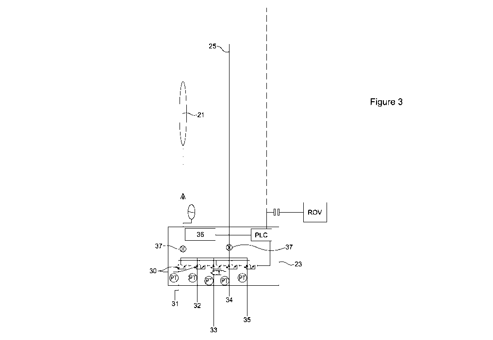
A system for hydraulically controlling a subsea device, the system comprising a compensator provided within a cavity of a well system, a hydraulic connection between the compensator and the subsea device, a pressure regulator arranged to regulate the hydraulic pressure provided to the subsea device and a ventilation tool for releasing pressure at the subsea device.


French Abstract

La présente invention concerne un système de commande hydraulique d'un dispositif sous-marin, le système comprenant un compensateur prévu à l'intérieur d'une cavité d'un système de puits, un raccord hydraulique entre le compensateur et le dispositif sous-marin, un régulateur de pression agencé pour réguler la pression hydraulique fournie au dispositif sous-marin et un outil de ventilation pour réduire la pression au niveau du dispositif sous-marin.

Claims

Note: Claims are shown in the official language in which they were submitted.


6

CLAIMS:

1. A system for hydraulically controlling a subsea device, the system
comprising:
a compensator provided within a cavity of a well system,
a hydraulic connection between the compensator and the subsea device,
a pressure regulator arranged to regulate the hydraulic pressure provided to
the
subsea device,
a ventilation tool for releasing pressure at the subsea device.
2. The system according to claim 1 , further comprising a second pressure
regulator for controlling the pressure in the cavity.
3. The system according to claim 1 or 2, wherein the cavity is provided
within a
blow-out preventer.
4. The system according to claim 1 or 2, wherein the cavity is provided
within an
annulus above the blow-out preventer.
5. The system according to claim 2, wherein the second pressure regulator
is
provided below a choke line.
6. The system according to any one of the preceding claims, wherein the
compensator is a bladder or a piston.
7. The system according to any one of the preceding claims, wherein the
subsea
device is a tubing hanger running tool or a tubing hanger.
8. The system according to any one of the preceding claims, further
comprising a
flowmeter for determining the amount of fluid which has passed towards the
subsea
device.
9. The system according to any one of the preceding claims, wherein the
subsea
device is a wellhead cleaning tool.


7

10. The system according to any one of the preceding claims, wherein the
cavity is
an annulus above a tubing hanger.
11. The system according to any one of the preceding claims, wherein the
cavity is
provided below an upper annular valve.
12. A method of hydraulically controlling a subsea device, the method
comprising:
providing a compensator within a cavity of a well system,
providing a hydraulic connection between the compensator and the
subsea device,
controlling the pressure within the cavity,
regulating hydraulic pressure from the compensator to the subsea
device.
13. The method according to claim 12, wherein the cavity is provided within
a blow-
out preventer.
14. The method according to claim 12 or 13, wherein controlling the
pressure within
the cavity comprises closing a valve.
15. The method according to claims 12 to 14, wherein regulating hydraulic
pressure
from the compensator to the subsea device comprises controlling the pressure
to a
plurality of outlets towards the subsea device and wherein each of the
plurality of
outlets controls a function of the subsea device.
16. The method according to any one of claims 12 to 15, further comprising
measuring the amount of fluid which flows towards the subsea device.

Description

Note: Descriptions are shown in the official language in which they were submitted.


CA 03068549 2019-12-27
WO 2019/004842
PCT/N02018/050173
1
Tubing Hanger installation Tool
The invention relates to a method of subsea well intervention, and in
particular to
installation of a tubing hanger tool and operation of a tubing hanger
installation tool.
Control of subsea tools at a wellhead is challenging due to the distance to a
vessel or
platform at the sea surface. An umbilical may be used to carry power and
control
signals from the sea surface to the wellhead. An example of a subsea tool is a
tubing
hanger running tool. A tubing hanger is a support for a production tubing or
casing and
is provided in a Christmas tree, a dedicated tubing spool or a wellhead. The
tubing
hanger may also have openings for hydraulic or electronic control lines, or
chemical
injection lines. The tubing hanger can also provide a seal for the annulus and

production areas beneath the hanger. A tubing hanger running tool is used for
installing the tubing hanger and is operated by hydraulic power. The hydraulic
power is
traditionally included in an umbilical running from a vessel or platform at
the sea
surface to the tubing hanger running tool.
According to a first aspect of the invention there is provided a system for
hydraulically
controlling a subsea device, the system comprising a compensator provided
within a
cavity of a well system, a hydraulic connection between the compensator and
the
subsea device, a pressure regulator arranged to regulate the hydraulic
pressure
provided to the subsea device and a ventilation tool for releasing pressure at
the
subsea device.
The system may further comprise a second pressure regulator for controlling
the
pressure in the cavity, and optionally the pressure regulator may be provided
below a
choke line. The cavity may be provided within a blow-out preventer or within
an
annulus above the blow-out preventer or within an annulus above a tubing
hanger.
The cavity may be provided below an upper annular valve.
The compensator may be a bladder or a piston. The subsea device is a tubing
hanger
running tool or a tubing hanger. Alternatively, the subsea device may be a
wellhead
cleaning tool.

CA 03068549 2019-12-27
WO 2019/004842
PCT/N02018/050173
2
The system may further comprise a flowmeter for determining the amount of
fluid which
has passed towards the subsea device.
According to a second aspect of the invention, there is provided method of
hydraulically
controlling a subsea device, the method comprising providing a compensator
within a
cavity of a well system, providing a hydraulic connection between the
compensator and
the subsea device, controlling the pressure within the cavity, and regulating
hydraulic
pressure from the compensator to the subsea device.
The cavity may be provided within a blow-out preventer. Controlling the
pressure
within the cavity may comprise closing a valve. Regulating hydraulic pressure
from the
compensator to the subsea device may comprise controlling the pressure to a
plurality
of outlets towards the subsea device and each of the plurality of outlets may
control a
function of the subsea device. The method may further comprise measuring the
amount of fluid which flows towards the subsea device.
Some embodiments of the invention will now be described by way of example only
and
with reference to the accompanying drawings, in which:
Figure 1 illustrates a wellhead system including a hydraulic control system;
Figure 2 illustrates the hydraulic control system;
Figure 3 illustrates the hydraulic control system in more detail; and
Figure 4 is a flow diagram of a method.
The inventors have appreciated a need for a local supply of hydraulic power at
the
wellhead, in particular for the application of a tubing hanger running tool. A
cavity in
the wellhead system can be used to build up pressure. For example, a cavity in
a
blow-out preventer or Christmas tree, or an annulus in a tubular above the
wellhead
can be isolated from their respective outlets such that pressure builds up as
a result of
fluids entering the cavity without being able to leave the cavity. A
compensator is
provided within the cavity and connected to a hydraulic line such that the
pressure
differential between the cavity and the hydraulic fluid within the compensator
and
hydraulic line is fixed, and the pressure differential is close to zero or
zero in a specific
example. Examples of compensators are a bladder made of an appropriate
flexible
material or a piston.

CA 03068549 2019-12-27
WO 2019/004842
PCT/N02018/050173
3
The pressurised hydraulic lines are connected to a regulator before being
coupled to
the tool for driving the operation of the tool. The hydraulic control system
for driving the
operation of the tool further includes a ventilation tool for releasing the
hydraulic
pressure at the tool. The ventilation tool is provided in an area with lower
pressure
than the hydraulic pressure of the system such that pressure can be released,
for
example an area above the annular of the blow-out preventer.
Further, a flowmeter may be provided before the running tool. The flowmeter
will
indicate how much fluid has passed the hydraulic line towards to the running
tool, and
from those data an operator or a control system can determine how far a moving
part
of the running tool has travelled as a result of the hydraulic flow.
Using a blow-out preventer (BOP) cavity to provide pressurised fluid instead
of a
hydraulic pressure unit (HPU) on a rig at the sea surface together with an
umbilical
reduces complexity and costs. Instead of bringing hydraulic pressure from the
surface
down to the wellhead, the present system is based on using the BOP to create
the
pressure. In addition, the water depth will have no direct impact on the way
the system
works because the hydraulic pressure is only determined by the BOP cavity
pressure.
Communication with the hydraulic pressure system can take place through the
BOP or
via a communication cable from a drill floor.
A particular embodiment is illustrated in Fig. 1. A BOP 11 is illustrated
which includes
several standard sealing elements: a blind shear ram (BSR), a casing shear ram
(CSR), an upper pipe ram (UPR), middle pipe ram (MPR) and lower pipe ram
(LPR).
Further illustrated are a choke line (12) and a kill line (13).
A bladder 13 is provided within a cavity and the bladder acts as a compensator
for
driving the running tool. The bladder is provided in the cavity between the
MPR and
the annular, but other cavities may also be used.
The hydraulic pressure system is illustrated in Fig. 2 in which the rest of
the BOP is
omitted for clarity. Bladders 21 are illustrated which are the same as
bladders 13 in
Fig. 1. The bladders are connected to a control unit 23 by hydraulic lines 22.
Control

CA 03068549 2019-12-27
WO 2019/004842
PCT/N02018/050173
4
unit 23 has several hydraulic outlets 24 towards the running tool for
controlling different
functions of the running tool. When intervention is required, a remotely
operated
vehicle (ROV) can optionally be used to access the device by way of suitable
connections. Instead of an ROV or in addition to an ROV, however, it is also
possible to
use a communication cable from the surface towards the control unit. The
communication cable can run through a slick part of the upper annular. A
hydraulic
release line 25 extends upwards towards a ventilation tool 26. In this
example, the
ventilation tool is provided above the annular of the BOP.
Figure 3 illustrates more detail of the control unit of the hydraulic control
device. A
bladder 21 and hydraulic release line 25 are provided as in Fig. 2. Controller
23 is
used to distribute and control the hydraulic pressure outlets towards the
running tool.
The outputs are controlled by hydraulic control valves 30. The outputs of the
illustrated
embodiment are connected to the running tool functions as follows: running
tool latch
(31), running tool unlock (32), tubing hanger unlock (33), tubing hanger lock
(34), and
tubing hanger verification (35). Further, a programmable logic controller
(PLC) and/or
a battery (36) are provided. Flowmeters 37 are provided which can be used to
determine the travelled distance of tubing hanger components or tubing hanger
running
tools. Signals may be provided from the surface to the control unit by way of
a control
cable, or alternatively an ROV can be used to instruct the control unit.
The hydraulic output of the hydraulic pressure system illustrated in Figs. 1
to 3 can be
used for any relevant device which operates based on hydraulic pressure. Other

examples are as follows. An hydraulic wellhead cleaning tool which may be used
for
cleaning the wellhead seal surface. Hydraulic activation tools for the BOP
itself could
be based on this hydraulic pressure system, but it should be noted that in the

configuration of Fig. 1 the pressure in the illustrated cavity will drop if
one of the shear
rams is activated.
A method is illustrated in fig. 4, comprising the steps of: providing a
compensator in a
cavity (51), providing a hydraulic connection between the compensator and a
subsea
device (S2), controlling the pressure in the cavity (S3) and regulating the
hydraulic
pressure to the subsea device (S4).

CA 03068549 2019-12-27
WO 2019/004842
PCT/N02018/050173
Although the invention has been described in terms of preferred embodiments as
set
forth above, it should be understood that these embodiments are illustrative
only and
that the claims are not limited to those embodiments. Those skilled in the art
will be
able to make modifications and alternatives in view of the disclosure which
are
5 contemplated as falling within the scope of the appended claims. Each
feature
disclosed or illustrated in the present specification may be incorporated in
the
invention, whether alone or in any appropriate combination with any other
feature
disclosed or illustrated herein.

Representative Drawing
A single figure which represents the drawing illustrating the invention.
Administrative Status

For a clearer understanding of the status of the application/patent presented on this page, the site Disclaimer , as well as the definitions for Patent , Administrative Status , Maintenance Fee  and Payment History  should be consulted.

Administrative Status

Title Date
Forecasted Issue Date Unavailable
(86) PCT Filing Date 2018-06-29
(87) PCT Publication Date 2019-01-03
(85) National Entry 2019-12-27
Examination Requested 2022-04-27

Abandonment History

There is no abandonment history.

Maintenance Fee

Last Payment of $210.51 was received on 2023-11-07


 Upcoming maintenance fee amounts

Description Date Amount
Next Payment if small entity fee 2025-06-30 $100.00
Next Payment if standard fee 2025-06-30 $277.00

Note : If the full payment has not been received on or before the date indicated, a further fee may be required which may be one of the following

  • the reinstatement fee;
  • the late payment fee; or
  • additional fee to reverse deemed expiry.

Patent fees are adjusted on the 1st of January every year. The amounts above are the current amounts if received by December 31 of the current year.
Please refer to the CIPO Patent Fees web page to see all current fee amounts.

Payment History

Fee Type Anniversary Year Due Date Amount Paid Paid Date
Application Fee 2019-12-27 $400.00 2019-12-27
Maintenance Fee - Application - New Act 2 2020-06-29 $100.00 2019-12-27
Registration of a document - section 124 $100.00 2020-06-04
Maintenance Fee - Application - New Act 3 2021-06-29 $100.00 2021-06-01
Request for Examination 2023-06-29 $814.37 2022-04-27
Maintenance Fee - Application - New Act 4 2022-06-29 $100.00 2022-06-03
Maintenance Fee - Application - New Act 5 2023-06-29 $210.51 2023-06-01
Maintenance Fee - Application - New Act 6 2024-07-02 $210.51 2023-11-07
Owners on Record

Note: Records showing the ownership history in alphabetical order.

Current Owners on Record
EQUINOR ENERGY AS
Past Owners on Record
None
Past Owners that do not appear in the "Owners on Record" listing will appear in other documentation within the application.
Documents

To view selected files, please enter reCAPTCHA code :


To view images, click a link in the Document Description column. To download the documents, select one or more checkboxes in the first column and then click the "Download Selected in PDF format (Zip Archive)" or the "Download Selected as Single PDF" button.

List of published and non-published patent-specific documents on the CPD .

If you have any difficulty accessing content, you can call the Client Service Centre at 1-866-997-1936 or send them an e-mail at CIPO Client Service Centre.


Document
Description 
Date
(yyyy-mm-dd) 
Number of pages   Size of Image (KB) 
Abstract 2019-12-27 2 55
Claims 2019-12-27 2 53
Drawings 2019-12-27 3 26
Description 2019-12-27 5 189
Representative Drawing 2019-12-27 1 7
Patent Cooperation Treaty (PCT) 2019-12-27 3 124
Patent Cooperation Treaty (PCT) 2019-12-27 2 53
International Search Report 2019-12-27 2 120
National Entry Request 2019-12-27 3 90
Cover Page 2020-02-12 1 30
Request for Examination 2022-04-27 4 117
Examiner Requisition 2023-07-07 4 221
Amendment 2023-08-03 5 115
Amendment 2023-11-03 18 640
Description 2023-11-03 5 282
Claims 2023-11-03 2 93
Drawings 2023-11-03 3 46