Note: Descriptions are shown in the official language in which they were submitted.
CA 03068721 2019-12-30
WO 2019/027713 PCT/US2018/043347
[001] IRRIGATION BOOT ASSEMBLY
[002] RELATED APPLICATIONS
[003] The present invention claims priority to U.S. Provisional Application
No. 62/539,731
filed August 1, 2017.
[004] BACKGROUND AND FIELD OF THE PRESENT INVENTION
[005] Field of the Present invention
[006] The present invention relates to an irrigation boot assembly for
securing span pipes.
[007] Background of the Invention
[008] Straight walled flex boots are used across the mechanized irrigation
industry to make
water tight connections between span pipes and other pipe joints. An example
of a straight
walled flex boot 10 is shown in Figure 1. As shown, these boots 12 are
generally constructed
of heavy, multiple ply rubber material (such as 4 ply EPDM with polyester yarn
or the like)
and wrapped around two adjoining sections of pipe 14, 16 to handle high forces
due to
pressure and movement in the span or pipe joint.
[009] Commonly, the boots 12 are secured to the outside of the span pipes via
large flex
boot clamps 18. Extra clamps, longer boots, and even tabbed boots 19 (as shown
in Figure 1)
are used to prevent the boot from slipping off in rough terrain through many
cycles.
However, despite the extra supports and tabs used, the present designs for
boots on irrigation
systems are unable to provide consistent, long-term support for connecting
span pipes.
Instead, the flex boots of the prior art are prone to slippage and tears after
repeated use.
[0010] In order to overcome the limitations of the prior art, the present
invention provides a
span boot with a reinforced, bellow design which overcomes the many problems
that have
been observed over the years with straight walled span boots.
[0011] Summary of the Present Invention
[0012] The present invention discloses an irrigation boot assembly for
securing span pipes.
According to a preferred embodiment, an irrigation boot assembly of the
present invention
may preferably include a center body portion formed as a laterally extending,
hollow tube
having a first side opening and a second side opening for receiving and
securing connected
span pipes. According to a further preferred embodiment, the irrigation boot
assembly of the
present invention preferably further includes securing straps extending around
the first and
1
CA 03068721 2019-12-30
WO 2019/027713 PCT/US2018/043347
second side openings. According to a further preferred embodiment, the center
body portion
of the present invention preferably further includes a plurality of bellows
which each include
a ridge portion extending above the surface of the center body portion.
According to a
further preferred embodiment, the bellows of the present invention may
preferably be formed
to compress and extend in response to lateral and angular forces applied due
to the
misalignment of the first and second span pipes. According to a further
preferred
embodiment, the center body portion of the present invention may preferably
further include
a plurality of valleys which are positioned between each of the plurality of
bellows and which
may include reinforcing bands within each valley.
[0013] The accompanying drawings, which are incorporated in and constitute
part of the
specification, illustrate various embodiments of the present invention and
together with the
description, serve to explain the principles of the present invention.
[0014] Brief Description of the Drawings
[0015] FIG. 1 shows a straight walled flex boot of the prior art.
[0016] FIG. 2 shows an exemplary flex boot in accordance with a first
preferred embodiment
of the present invention.
[0017] FIG. 3 shows the exemplary flex boot of FIG. 2 with bellows in a
laterally extended
position.
[0018] FIG. 4 shows overhead views of the exemplary flex boot of FIG. 2 while
being flexed.
[0019] FIG. 5 shows an exemplary flex boot in accordance with an alternative
embodiment
of the present invention.
[0020] FIG. 6A shows an overhead view of the exemplary flex boot of FIG. 5
with the
forward bellow ridges compressed and the rear bellow ridges flexed.
[0021] FIG. 6B shows an overhead view of the exemplary flex boot of FIG. 5
with the
forward bellow ridges extended and the rear bellow ridges compressed.
[0022] FIG. 7 shows an exemplary flex boot in accordance with a further
alternative
embodiment of the present invention.
[0023] FIG. 8 shows the exemplary flex boot of FIG. 7 while being laterally
extended.
2
CA 03068721 2019-12-30
WO 2019/027713 PCT/US2018/043347
[0024] Description of the Preferred Embodiments
[0025] For the purposes of promoting an understanding of the principles of the
present
invention, reference will now be made to the embodiments illustrated in the
drawings and
specific language will be used to describe the same. It will nevertheless be
understood that
no limitation of the scope of the present invention is hereby intended and
such alterations and
further modifications in the illustrated devices are contemplated as would
normally occur to
one skilled in the art.
[0026] The main features and preferences of the present invention and
preferred
embodiments of same have been described in general. As can be appreciated, any
number of
variations of these features may be implemented on other embodiments of the
present
invention. Further modifications may also be made which do not necessarily
alter the
fundamental characteristics of the invention. It is considered that such
variants and modified
embodiments still fall within the scope of the present invention which, in its
preferred form,
includes an enhanced flex boot with bellows.
[0027] Referring now to FIGS. 2-8, an exemplary vehicle embodying aspects of
the present
invention shall now be discussed. It should be understood in this discussion
that each aspect
of the disclosed invention may be used individually or in combination with a
variety of other
features without departing from the scope and spirit of the present invention.
[0028] Referring now to FIG. 2, a first exemplary flex boot 20 in accordance
with a first
preferred embodiment of the present invention shall now be discussed. As shown
in FIG. 2,
the exemplary flex boot 20 may preferably include a center body portion 21
which is
preferably formed as a laterally extending, hollow tube. As further shown, the
center body
portion 21 preferably has a diameter greater than that of span pipes 22 and
23. In this way,
span pipes 22 and 23 may be inserted into the center body portion 21 and
secured via
securing straps/clamps 24, 25 respectively. As further shown, the center body
portion 21
preferably further includes a plurality of ridged bellows 27 which are
preferably formed to
compress and extend in response to lateral and angular forces applied due to
the
misalignment of the span pipes 22, 23. According to a further preferred
embodiment, the
valleys of the bellows may be reinforced by reinforcing bands 25, 26 which may
be formed
of metal, plastic or fabric rings/bands secured within each valley. According
to a further
preferred embodiment, the exemplary flex boot 20 of the present invention may
include a
center body portion 21 having four bellows extending around the circumference
of the center
3
CA 03068721 2019-12-30
WO 2019/027713 PCT/US2018/043347
body portion 21. According to a further preferred embodiment, the bellows may
together
extend for an approximate length of 7 inches. According to a still further
preferred
embodiment, the bellows may preferably be formed as generally semicircular
ridges
extending above and wrapping around the center body portion 21. According to a
further
preferred embodiment, the semicircular ridges may have an outer circumference
of 2.47
inches. Alternatively, it should be understood that the number of bellows may
be varied as
needed (such as from 2-25 bellows) and that the bellows may together extend
over any
distance as needed (such as from 1-15 inches). Further, it should be
understood that the outer
circumference of each bellow may be varied as needed (such as from 0.5- 5.0
inches).
[0029] According to preferred embodiments, the bellows of the present
invention may
preferably be incorporated into the wall(s) of the center body portion to form
concertinaed
sides to allow the center body portion to expand and contract and thus absorb
any movement,
especially axial elongation between irrigation pipes. Structurally, each
bellow may be
formed to include a ridge extending around the surface of the center body
portion with lower
height regions ("valleys") located between each bellow ridge. According to
alternative
preferred embodiments, the bellows may be v-shaped or circular shaped as
discussed further
below. As also discussed further below, the irrigation boot of the present
invention may
preferably further include support rings/bands to support the valleys of the
bellows when
under pressure.
[0030] With reference now to FIG. 3, the exemplary flex boot 20 of FIG. 2 is
shown with the
bellows 25 in a laterally extended position. As shown in FIG. 3, in accordance
with a further
preferred embodiment, the lateral extension of the bellows 25 may preferably
allow the
lateral length of the bellows 25 to increase from an overall lateral length of
7 inches (as
discussed above) to an overall lateral length of 9.9 inches or greater.
Alternatively, it should
be understood that the number and size of the bellows may be varied to allow
for variations
in the extended length as needed (i.e. such as allowing extensions in the
range of 1-20
inches).
[0031] Referring now to FIG. 4, overhead views of the exemplary flex boot of
FIG. 2 being
flexed are provided to illustrate the movement and limits for exemplary 6 5/8"
spans. The
views of FIG. 4 illustrate that as an irrigation machine incorporating the
present invention
moves over terrain, the span joints experience what is referred to as slope
absorption. When
this occurs, the primary actions of the boot assembly of the present invention
will either be
elongation with positive slope absorption or contraction in the case of
negative slope
4
CA 03068721 2019-12-30
WO 2019/027713 PCT/US2018/043347
absorption. Further, the boot assembly of the present invention may preferably
further allow
twisting in combination with elongation or contraction. In this way, the
exemplary flex boot
of the present invention may include interconnected sections which are
rotationally connected
to allow rotational movement between each section as discussed with respect to
FIG. 7
below.
[0032] As shown in a first view 30, the exemplary flex boot of the present
invention may
initially be substantially laterally aligned with the joined span pipes (i.e.
net angle between
pipes of 0 degrees). As illustrated, when the span joint is straight (which is
not its normal
state due to span crown) the distance between the pipe ends is 7". As shown in
a second view
32, the exemplary flex boot may flex rearward to allow for a net rearward
angle between the
span pipes of anywhere between 0-180 degrees. In the specific example shown,
when the
exemplary spans undergo a 30% (16.7 degrees) slope absorption, the
rearward/bottom of the
pipe faces are shown moving to become 9.76" apart with the boot of the present
invention
elongating from 7" to 9.76" (or 39%) to accommodate this movement. As shown in
a third
view 34, the exemplary flex boot may further flex forward to allow for a net
forward angle
between span pipes of anywhere between 0-180 degrees.
[0033] With reference now to FIG. 5, an exemplary flex boot 40 in accordance
with an
alternative embodiment of the present invention shall now be discussed. As
shown, an
exemplary flex boot 40 may include a center body portion 41 which extends
around and
secures a pair of pipe sections 44, 45 via securing straps/clamps 46, 47.
Further, the
exemplary flex boot 40 may preferably further include one or more bellows 42
which extend
around the center body portion 41. As further shown, the bellows 42 in
accordance with an
alternative preferred embodiment may be formed in a variety of shapes
including pyramid,
triangular or other angular shapes.
[0034] With reference now to FIGS. 6A and 6B, flexed views of the exemplary
preferred
embodiment of FIG. 5 are shown. As shown in FIG. 6A, the exemplary flex boot
40 of FIG.
is shown with the forward bellow ridges 42a compressed and the rear bellow
ridges 42b
extended. In FIG. 6B, the same exemplary flex boot 40 of FIG. 5 is shown with
the forward
bellow ridges 43a extended and the rear bellow ridges 43b compressed.
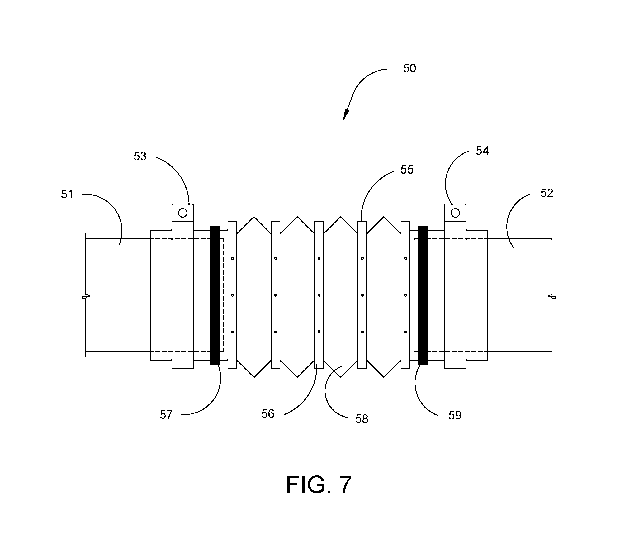
[0035] With reference now to FIG. 7, a further alternative preferred
embodiment of a flex
boot 50 in accordance with a further alternative embodiment of the present
invention shall
now be discussed. As shown, an exemplary flex boot 50 may include a center
body portion
5
CA 03068721 2019-12-30
WO 2019/027713 PCT/US2018/043347
55 which extends around and secures a pair of pipe sections 51, 52 via
securing straps/clamps
53, 54. As further shown, the exemplary flex boot 50 may preferably further
include one or
more bellows 58 which extend around the center body portion 55. As further
shown, the flex
boot 50 may further include reinforcement bands 56 which may be formed of a
metal, plastic
or fabric strips or bands secured into the valleys between each bellow 58.
FIG. 8 shows the
exemplary flex boot 50 of FIG. 7 with each bellow 58 laterally extended as
discussed with
respect to FIGS. 2 and 3 above.
[0036] With further reference to FIG. 7, the exemplary flex boot 50 of the
present invention
may further include a plurality of rotational bearings 57, 59 which preferably
rotate in
response to any transferred rotation movement of the attached span pipes 51,
52.
Accordingly, where span pipe 51 rotates (spins forward or backwards) about its
axis,
rotational bearing 57 preferably may internally rotates as needed to minimize
the transfer of
rotational forces into main body 55 of the flex boot 50. Likewise, where span
pipe 52 rotates
(spins forward or backwards) around its axis, rotational bearing 59 preferably
internally
rotates as needed to minimize the transfer of rotational force into the main
body 55 of the flex
boot 50. According to a preferred embodiment, the rotational bearings 57, 59
preferably may
be of any form to allow independent rotation between the span pipes and the
main body 55 of
the flex boot 50. For example, these may include: slewing bearings, composite
bearings, ball
bearings, roller bearings or any other type of bearing or rotational
mechanism.
[0037] While the above descriptions regarding the present invention contain
much
specificity, these should not be construed as limitations on the scope, but
rather as examples.
Many other variations are possible. Accordingly, the scope of the present
invention should
be determined not by the embodiments illustrated, but by the appended claims
and their legal
equivalents.
6