Note: Descriptions are shown in the official language in which they were submitted.
CA 03069318 2020-01-07
WO 2019/014416
PCT/US2018/041760
SYSTEMS AND METHODS FOR DEWATERING A SLURRY THAT INCLUDES
LIGNOCELLULOSIC BIOMASS AND LIQUID
CROSS-REFRENCE TO RELATED APPLICATION
This application claims priority to provisional patent application entitled
"SYSTEMS
AND METHODS FOR DEWATERING A SLURRY THAT INCLUDES
LIGNOCELLULOSIC BIOMASS AND LIQUID" filed on July 13, 2017, and having serial
number 62/532,228, wherein the entirety of said provisional patent application
is
incorporated herein by reference.
BACKGROUND
The present disclosure relates to dewatering a slurry that includes
lignocellulosic
biomass and an aqueous liquid (e.g., water) and introducing the dewatered
lignocellulosic
biomass into a downstream process of a biorefinery having a gaseous headspace
under
pressure.
SUMMARY
Embodiments of the present disclosure include a system for dewatering a
lignocellulosic biomass slurry, wherein the system includes:
a) a source of a lignocellulosic biomass slurry, wherein the lignocellulosic
biomass
slurry includes:
i) lignocellulosic biomass; and
ii) water;
b) a dewatering system in fluid communication with the source of the
lignocellulosic
biomass slurry, and adapted to receive the lignocellulosic biomass slurry to
separate at least a
portion of the water from the lignocellulosic biomass slurry, wherein the
dewatering system
includes at least a solids transfer device having a housing including an inlet
and an outlet,
wherein the solids transfer device is adapted to convey and accumulate
dewatered
lignocellulosic biomass promixal to the outlet of the solids transfer device,
wherein a
headspace occupied by a gas is present at least at the inlet of the solids
transfer device,
wherein the headspace is at a first pressure; and
c) at least one vessel in fluid communication with the outlet of the solids
transfer
device, wherein the vessel is configured to receive the accumulated dewatered
lignocellulosic
biomass and process the dewatered lignocellulosic biomass, wherein the vessel
has a
headspace that is occupied by a gas that is at a second pressure, wherein the
first pressure has
1
CA 03069318 2020-01-07
WO 2019/014416
PCT/US2018/041760
a value that inhibits the gas in the vessel from flowing back through the
solids transfer
device.
Embodiments of the present disclosure also include a method of dewatering a
lignocellulosic biomass slurry, wherein the method includes:
a) providing a lignocellulosic biomass slurry to a dewatering system having an
inlet
and an outlet, wherein the lignocellulosic biomass slurry includes
lignocellulosic biomass and
water;
b) separating at least a portion of the water from the lignocellulosic biomass
slurry in
the dewatering system to form a dewatered lignocellulosic biomass, wherein the
dewatering
system includes a headspace occupied by a gas at a first pressure;
c) conveying the lignocellulosic biomass through the dewatering system to
accumulate the dewatered lignocellulosic biomass proximal to the outlet of the
dewatering
system; and
d) providing the accumulated dewatered lignocellulosic biomass to at least one
vessel
in fluid communication with the dewatering system, wherein the vessel has a
headspace that
is occupied by a gas that is at a second pressure, wherein the first pressure
has a value that
inhibits the gas in the vessel from flowing into the dewatering system.
BRIEF DESCRIPTION OF THE DRAWINGS
FIG. 1 shows a schematic process flow diagram of an embodiment of the present
disclosure;
FIG. 2A shows a schematic process flow diagram of another embodiment of the
present disclosure;
FIG. 2B shows a portion of an embodiment of the solids transfer device in FIG.
2A;
and
FIG. 3 shows a schematic process flow diagram of another embodiment of the
present
disclosure.
DETAILED DESCRIPTION
Disclosed in embodiments herein are systems and methods for dewatering a
lignocellulosic biomass slurry in a biorefmery and transferring the dewatered
lignocellulosic
biomass into a pressurized environment for further processing of the
lignocellulosic biomass.
One or more advantages of systems and methods according to the present
disclosure are
described throughout the application. Illustrative examples are described
herein below with
respect to FIGS. 1 and 2.
2
CA 03069318 2020-01-07
WO 2019/014416
PCT/US2018/041760
Methods and systems according to an illustrative example of the present
disclosure
can be used to dewater lignocellulosic biomass obtained from one or more
sources of a
lignocellulosic biomass slurry. As used herein, a lignocellulosic biomass
slurry is a
composition that includes at least lignocellulosic biomass and water.
Lignocellulosic biomass includes residual agricultural material from
harvesting such
as corn stover (e.g., corn cobs, stalks and leaves), fiber from the corn
kernel, switchgrass,
wood chips or other wood waste, and other plant matter (grown for processing
into
bioproducts or for other purposes). Lignocellulosic biomass includes
hemicellulose,
cellulose, and lignin.
The lignocellulosic biomass present in a slurry can be processed from
feedstock prior
to or while forming a slurry. Lignocellulosic biomass feedstock can be
processed by a
variety of techniques such as size reduction, washing, steaming, combinations
of these, and
the like. For example, a biomass lignocellulosic feedstock can be prepared by
grinding the
lignocellulosic biomass feedstock in one or more grinders into ground solids
to reduce the
size of the feedstock and increase its surface area for subsequent processing
such as
hydrolysis.
Lignocellulosic biomass can be combined with one or more sources of liquids
that
include water for forming a slurry. Nonlimiting examples of water sources
include recycled
process water from one or more points in a biorefmery, fresh tap water,
combinations of
these, and the like. Recycled process water can be treated or not treated
prior to being
combined with lignocellulosic biomass.
In some embodiments, amounts of lignocellulosic biomass and liquid (e.g.,
water) can
be combined so that a lignocellulosic biomass slurry has a total solids
content of 1 to 10
percent, from 2 to 9 percent, or even 3 to 8 percent. As used herein, "total
solids content"
means the total content of dissolved and suspended solids based on the total
weight of the
lignocellulosic biomass slurry.
An example of forming a lignocellulosic biomass slurry is described below in
connection
with FIGS. 2A and 2B.
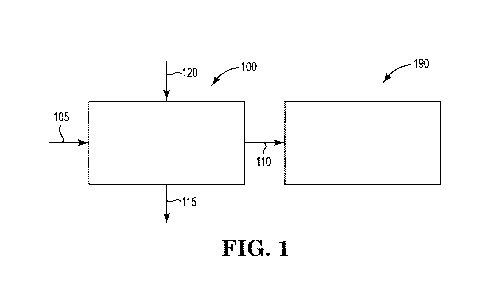
In the illustrative example of FIG. 1, a source of a lignocellulosic biomass
slurry 105
is provided to (e.g., pumped to) a dewatering system 100 that is adapted to
receive the
lignocellulosic biomass slurry. For example, the source of a lignocellulosic
biomass slurry
105 can be provided to system 100 via one or more pumps and associated piping
and valves.
A dewatering system 100 according to the present disclosure includes at least
a solids transfer
device having an inlet and an outlet and that is adapted to convey and
compress the
3
CA 03069318 2020-01-07
WO 2019/014416
PCT/US2018/041760
lignocellulosic biomass to separate at least a portion of the water from the
lignocellulosic
biomass slurry 105 and form accumulated biomass110 comprising the dewatered
lignocellulosic biomass. As shown in FIG. 1, the liquid (e.g., water) 115 that
is removed
from the lignocellulosic biomass slurry 105 can be discharged from the
dewatering system
100 via stream 115. In some embodiments, the liquid stream 115 can be recycled
to one or
more points upstream and/or downstream in a biorefinery.
A biorefinery can include many unit operations that are configured to treat
lignocellulosic biomass for a variety of purposes, especially after
lignocellulosic biomass has
been dewatered from a slurry. Many such unit operations include a headspace
occupied by a
gas (e.g., air and steam) that is at an elevated pressure relative to upstream
processes and/or
the ambient environment. As shown in FIG. 1, downstream of the dewatering
system 100 is
a system 190 that includes at least one vessel in fluid communication with the
outlet of the
solids transfer device in the dewatering system 100. The vessel is configured
to receive the
accumulated dewatered biomass 110 and process the dewatered lignocellulosic
biomass. The
vessel has a headspace that is occupied by a gas that is at a pressure.
Because the pressure in
the vessel of system 190 can be elevated relative to upstream processes and/or
the ambient
environment, there is a chance that the gas from system 190 can flow backwards
toward one
or more upstream processes. Such backward flow can be undesirable for several
reasons.
For example, such backward flow can be considered a "leak" and the pressurized
gas may
have to be replenished in system 190, which can be inefficient. If the gas
includes steam
(e.g., for heating, treating, and the like), then heat is also "leaked" out,
which can be
inefficient. Also, if steam were to leak back from system 190 into dewatering
system 100,
the liquid 115 may be heated to the point that it vaporizes. If the liquid 115
is being
reused/recycled, it may have to be condensed before being reused/recycled,
which can also be
inefficient.
In some embodiments, systems and methods according to the present disclosure
include the combination of a gas in the dewatering system 100 at a pressure
and accumulated
lignocellusoic biomass 110 to effectively prevent backflow of gas (e.g.,
steam) from system
190. Dewatering system 100 can be configured so that a gas is present in a
headspace of
.. dewatering system 100 at a pressure that, in combination with the
accumulated lignocellusoic
biomass110, prevents backflow of gas from system 190 to an undue degree. The
pressure of
the gas in the headspace of dewatering system 100 is substantially the same as
or greater than
the gas pressure in the headspace in system 190 to prevent backflow from
system 190.
Notwithstanding, the accumulated lignocellulosic biomass can help prevent
undue mixing of
4
CA 03069318 2020-01-07
WO 2019/014416
PCT/US2018/041760
gas from system 190 headspace with gas in system 100 headspace at the
interface of systems
100 and 190. The accumulated lignocellusoic biomass110 functions as a physical
baffle or
mat to help segregate the headspace in system 190 from the headspace in
dewatering system
100. It can be desirable to segregate the headspace in system 190 from the
headspace in
system 100 to prevent undue mixing at the interface of systems 100 and 190.
For example, if
system 190 includes steam, it can be desirable to prevent mixing at the
interface of systems
100 and 190 that may occur and introduce an undue amount of steam into system
100. It is
noted that the that the accumulated lignocellusoic biomass is not required to
be compressed to
a degree that it can form a seal to seal in the gas in system 190 from flowing
backwards
toward dewatering system 100. The pressure of the gas in the headspace of
dewatering
system 100 is substantially the same or greater than in the headspace in
system 190 to help
prevent backflow. The accumulated biomass helps to prevent undue mixing at the
interface.
This can be advantageous because some lignocellulosic biomass can have
variable particle
size and/or low bulk density making it difficult to compress it enough such
that it can form a
seal while at the same time having a desired throughput on a continuous basis.
It is the
combination of the accumulated lignocellulosic biomass 110 and gas pressure in
the
headspace of dewatering system 100 that prevents undue backflow and mixing of
gas from
system 190. Advantageously, such a configuration can operate at desirable
throughputs on a
continuous basis, which is surprising for some lignocellulosic biomass that is
challenging to
handle and process (e.g., corn stover and the like).
In some embodiments, dewatering system 100 includes a headspace that is
occupied
by a gas that is in fluid communication with at least the inlet of the solids
transfer device.
The gas pressure in the headspace of the dewatering system 100 (a first
pressure) can be
selected so that, in combination with the accumulated lignocellusoic
biomass110, it inhibits
the gas at a second pressure in the vessel of system 190 from flowing back
through the solids
transfer device to an undue degree. In some embodiments, the first and second
pressures can
be substantially the same. For example, the difference between the first
pressure and the
second pressure can be 5 psi or less, 1 psi or less, or even 0.5 psi or less.
In some
embodiments, the first pressure can be maintained at a pressure that is
greater than the second
pressure. For example, the first pressure can be maintained at a pressure of
from 0.5 to 30 psi
greater than the second pressure, from 0.5 to 20 psi greater than the second
pressure, from 0.5
to 10 psi greater than the second pressure, or even from 0.5 to 5 psi greater
than the second
pressure.
5
CA 03069318 2020-01-07
WO 2019/014416
PCT/US2018/041760
The gas present in the headspace of dewatering system 100 can be provided from
a
variety of sources. For example, at least a portion of the gas present at the
first pressure in
the headspace at the inlet of the solids transfer device in dewatering system
100 can be
supplied from gas that is entrained in the lignocellulosic biomass slurry 105.
Instead of or in
.. addition to any entrained gas, a dedicated source of compressed gas 120 can
be supplied to
the headspace of dewatering system 100. Examples of gas 120 include air, inert
gas (e.g.,
nitrogen), carbon dioxide, combinations of these, and the like. In some
embodiments, the
pressure in the headspace of the dewatering system 100 and the gas in the
headspace of
system 190 are greater than atmospheric pressure. For example, such pressures
can be
between 20 and 200 psig.
FIGS. 2A and 2B depict an illustrative example of the present disclosure. As
described below, the system in FIG. 2A can advantageously dewater a slurry of
ground
lignocellulosic biomass on a continuous basis and desired throughput, e.g., in
the context of a
biorefinery where the dewatered lignocellulosic biomass is subsequently
processed, e.g.,
hydrolyzed.
In a biorefinery, lignocellulosic biomass can be formed into a slurry using
one or
more tanks (with or without agitation such as mixing). A lignocellulosic
biomass slurry can
be prepared for one or more reasons such as making the lignocellulosic biomass
transportable
to one or more unit operations in a biorefinery, and to facilitate
distributing any treatment
compositions (e.g., acid compositions, base compositions, enzyme compositions,
combinations of these, and the like) throughout the lignocellulosic biomass.
As shown in
FIG. 2A, ground lignocellulosic biomass feedstock 201 is supplied to a slurry
system that
includes one or more slurry tanks 270. In some embodiments, the ground
lignocellulosic
biomass 201 includes ground corn stover having a particle size such that at
least 80 percent of
the ground corn stover passes through a screen having six inch openings, or
even a screen
having one inch openings, and less than 20 percent of the ground corn stover
passes through a
screen having 0.125 inch openings.
The ground lignocellulosic biomass feedstock 201 is combined with an aqueous
liquid
202 at a desirable ratio. For example, the ground lignocellulosic biomass
feedstock 201 can
be combined with an aqueous liquid 202 in a ratio so as to form a slurry
stream 205 having a
desirable total solids content (discussed above) and that is pumpable, e.g.,
via pump 280. A
lignocellulosic biomass slurry stream can be pumpable so that it can be
transferred to one or
more downstream processes via plumbing that includes, e.g., one or more pipes,
one or more
valves, and the like. A variety of pumps can be used to pump a lignocellulosic
biomass
6
CA 03069318 2020-01-07
WO 2019/014416
PCT/US2018/041760
slurry according to the present disclosure. Nonlimiting examples of such pumps
include
centrifugal pumps such as a screw centrifugal pump commercially available from
Hayward
Gordon under the tradename XCS screw centrifugal pump or from Vaughan under
the
tradename Triton screw centrifugal pump.
As shown in FIG. 2A, aqueous liquid 202 is obtained from at least streams 203,
250
and 260. Stream 203 can be fresh make-up water, recycled process water, or
combinations of
these. As shown, streams 250 and 260 are recycled from dewatering system 200,
which is
discussed below.
A slurry according to the present disclosure can be formed under a variety of
temperature and pressure conditions. In some embodiments, a slurry can be
formed in slurry
tank 270 at room temperature and atmospheric pressure.
As shown in FIG. 2A, after forming a lignocellulosic biomass slurry, the
slurry stream
205 can be pumped to a downstream process such as pretreatment reactor 290,
which can
have a gaseous headspace 291 at an elevated pressure, e.g., greater than
atmosphere pressure.
Before being introduced into pretreatment reactor 290, it may be desirable to
dewater the
lignocellulosic biomass present in the lignocellulosic biomass slurry stream
205.
Methods and systems according to the example of FIG. 2A include a dewatering
system 200 for dewatering the lignocellulosic biomass slurry from stream 205
so that at least
some liquid can be removed and the dewatered lignocellulosic biomass can be
introduced
into a system such as pretreatment reactor 290 without undue mixing and
backflow of gas
(e.g., steam) from pretreatment reactor 290 into dewatering system 200.
As shown in FIG. 2A, dewatering system 200 includes an enclosed screen device
240
directly coupled to a solids transfer device 230.
The lignocellulosic biomass slurry 205 is delivered to an inlet of screen
device 240,
where the slurry can undergo an initial dewatering.
As shown in FIG. 2A, enclosed screen device 240 includes a screen 241
positioned in
a housing 247 that can be pressurized.
The enclosed screen device 240 is adapted to receive the lignocellulosic
biomass
slurry stream 205 at a first end 242 of the screen 241 so that the slurry
flows down (at least in
part due to gravity) and across the screen 241 to separate at least a portion
of the water from
the lignocellulosic biomass slurry stream 205 and form a first dewatered
lignocellulosic
biomass that may include residual water from the lignocellulosic biomass
slurry stream 205,
and lignocellulosic biomass.
7
CA 03069318 2020-01-07
WO 2019/014416
PCT/US2018/041760
In some embodiments, at least 10%, at least 20%, at least 30%, at least 50%,
at least
60%, at least 70%, at least 80%, at least 90%, or even at least 95% of the
water present in the
slurry stream 205 that enters enclosed screen device 240 will pass through the
screen 241. In
some embodiments, the size of the screen openings can be selected to be small
enough to
permit substantially all of lignocellulosic biomass to not pass through the
openings. In some
embodiments, at least 50%, at least 60%, at least 70%, at least 80%, at least
90%, at least
95% , at least 99%, or even at least 99.9 % of the lignocellulosic biomass
will not pass
through the screen 241 as it passes down and across the screen 241.
The screen 241 has a plurality of openings 246. The plurality of openings 246
permit
liquid to pass through the screen 241 to separate at least a portion of the
water from the
lignocellulosic biomass slurry stream 205. The size of the screen openings 246
for screen
241 can be selected to achieve desirable dewatering of lignocellulosic biomass
in the slurry
205 while at the same time achieving desirable throughput on a continuous
basis. A screen
241 can have openings 246 that are all the same size or a plurality of
different sizes. In some
embodiments, the screen 241 may have one or more opening sizes of about 0.5
inches or less,
about 0.125 inches or less, or even about 0.0625 inches or less. In some
embodiments, the
screen 241 may include openings 246 having a size in the range from 0.03125
inches to 0.125
inches.
As shown, the screen 241 also has a second end 243 in addition to the first
end 242,
and the screen 241 is positioned (angled) so that first end 242 is above the
second end 243
relative to dashed horizontal line 245 and so that the screen 241 is at an
angle 244 greater
than zero relative to horizontal line 245. In some embodiments, the screen is
positioned
(angled) so that the screen 241 is at an angle 244 greater than 20 degrees, 30
degrees, 40
degrees, 50 degrees, 60 degrees, 70 degrees, 80 degrees, or even 90 degrees
relative to
horizontal line 245.
As shown in FIG. 2A, screen 241 is straight from the first end 242 to second
end 243.
Alternatively, the screen in the enclosed screen device could be curved and is
discussed below in connection with FIG. 3.
A wide variety of widths and lengths can be selected for screen 241 depending
on a
variety of factors such as, e.g., screen angle, desired throughput (gallons
per minute of
slurry), and the like. In some embodiments the length of screen 241 from first
end 242 to
second end 243 can be from 16 inches to 15 feet, from 30 inches to 10 feet, or
even from 40
inches to 9 feet. In some embodiments the width of screen 241 (perpendicular
to length) can
be from 10 inches to 10 feet, or even from 10 inches to 50 inches.
8
CA 03069318 2020-01-07
WO 2019/014416
PCT/US2018/041760
It has been found that by introducing the slurry stream 205 at the first end
242 (top
end) of an inclined screen 241 and letting the slurry flown down and across
the screen 241, at
least a portion of the liquid (e.g., water) can be separated from the
lignocellulosic biomass
without undue plugging of the screen 241. This dewatering technique can be
robust to
variations in solids loading, biomass size, and/or biomass shape (e.g., due to
grinding,
different forms of lignocellulosic biomass (e.g., corn husks as compared to
corn stalks, as
compared to corn cobs), and the like). In some embodiments, such dewatering
can be
performed continuously (e.g., days, weeks, etc.) without undue disruptions.
While not be
bound by theory, it is believed that by introducing the slurry 205 at the top
of an inclined
screen 241 permits a relatively high volume and/or velocity of the liquid near
the top end 242
to help keep the screen 241 from clogging with lignocellulosic biomass to an
undue degree,
especially flat biomass structures such as leaves and husks that are present
in corn stover.
Also, as the lignocellulosic biomass is dewatered as it passes down and across
the screen 241,
it can contact the screen 241 (e.g., due at least in part to gravity) and have
a "scrubbing"
effect that likewise helps keep the screen 241 from clogging with
lignocellulosic biomass to
an undue degree, especially flat biomass structures such as leaves and husks.
Exemplary angled screens 241 are commercially available as, e.g., "gravity
screens."
One example of a commercially available gravity screen can be obtained from
SWECO under
the tradename STA-SIEVE stationary screening device having model number SV1OS
BB.
Another example of a commercially available gravity screen can be obtained
from Parkson
Corporation under the tradename Hydroscreen solid, liquid separation
equipment. Another
example of a commercially available gravity screen can be obtained from Fluid-
Quip, Inc.
To facilitate transferring the dewatered lignocellulosic biomass from enclosed
screen device
240 to vessel 290 via solids transfer device 230, the enclosed screen device
240 has a
headspace 229 between the top of screen 241 and the housing 247 that can have
a gas present
at a pressure that, in combination with a accumulated dewatered
lignocellulosic biomass
exiting the solids transfer device 230, prevents mixing and backflow of gas
from vessel 290
through solids transfer device 230 to an undue degree. As shown in FIG. 2A,
the headspace
229 is in fluid communication with at least at the inlet 231 of the solids
transfer device 230
(e.g., screw conveyor or feeder). The gas pressure (a first pressure) in the
headspace 229 can
be selected so that, in combination with the accumulated dewatered
lignocellulosic biomass
from device 230, the gas in headspace 229 inhibits a gas (e.g., steam) at a
second pressure in
the headspace 291 of vessel 290 from flowing back through the solids transfer
device 230 to
an undue degree or mixing with any liquid or gas in system 200 to an undue
degree. In some
9
CA 03069318 2020-01-07
WO 2019/014416
PCT/US2018/041760
embodiments, the first and second pressures can be substantially the same. For
example, the
difference between the first pressure and the second pressure can be 1 psi or
less, or even 0.5
psi or less. In some embodiments, the first pressure can be maintained at a
pressure that is
greater than the second pressure. For example, the first pressure can be
maintained at a
pressure of 5 psi or greater than the second pressure, or even 10 psi or
greater.
The gas present in the headspace 229 can be provided from a variety of
sources. For
example, at least a portion of the gas present at the first pressure in the
headspace 229 at the
inlet 231 of the solids transfer device 230 can be supplied from gas that is
entrained in the
lignocellulosic biomass slurry stream 205. For example, while not being bound
by theory, it
is believed that mixing at high speeds in slurry thank 270 can create
turbulence that causes
gas (e.g., air) to be entrained in lignocellulosic biomass slurry. This
entrained gas may be
carried to the bottom of slurry tank 270 where it can enter pump 280 and be
compressed and
transported through one or more pipes in slurry stream 205. When the slurry
stream enters
the enclosed screen device 240, the gas can expand and escape the slurry to
the headspace
229 and create a pressurized headspace 229 near the inlet 231 of solids
transfer device 230.
Also, the slurry stream 205 can form a physical seal between the headspace 229
and the
slurry tank 270 so that the headspace 229 is at an elevated pressure relative
to a headspace in
the slurry tank, which may be at atmospheric pressure. In addition, slurry
stream 205
plumbing can include one or more valves to create a seal between headspace 229
and slurry
tank 270.
Instead of or in addition to any entrained gas, a dedicated source of
compressed gas
220 can be supplied to the headspace 229. Examples of gas 220 include air,
inert gas (e.g.,
nitrogen), carbon dioxide, combinations of these, and the like. In some
embodiments, the
pressure in the headspace 229 and the gas in the headspace 291 of vessel 290
are greater than
atmospheric pressure. For example, such pressures can be between 20 and 200
psig.
As mentioned above, the dewatering system 200 also includes a solids transfer
device
230 for transferring the dewatered, lignocellulosic biomass (first dewatered,
lignocellulosic
biomass) from enclosed screen device 240 into vessel 290.
As shown in FIG. 2A, solids transfer device 230 has an inlet 231 and an outlet
238,
and is adapted to convey the lignocellulosic biomass in the first dewatered,
lignocellulosic
biomass to separate at least a portion of the residual water 250 from the
first dewatered,
lignocellulosic biomass and accumulate second, dewatered lignocellulosic
biomass proximal
to outlet 238 so that it can be fed into vessel 290. In some embodiments, the
solids transfer
device 230 removes 50% or more of the residual water present in the first,
dewatered,
CA 03069318 2020-01-07
WO 2019/014416
PCT/US2018/041760
lignocellulosic biomass. In some embodiments, the solids transfer device 230
can remove
30% or less, 20% or less, or even 10% or less of the water present in the
first, dewatered,
lignocellulosic biomass.
A variety of solids transfer devices can be used to convey and compress
lignocellulosic biomass according to the present disclosure. As shown in FIG.
2A, solids
transfer device 230 includes a tubular trough or barrel member 232 having the
inlet 231 at
one end and the outlet 238 at the opposite end. The inlet 231 is adapted to
receive the first
dewatered lignocellulosic biomass at the first pressure in the headspace 229.
As shown in
FIG. 2B, the barrel member 232 can include a screw section 237 having a
rotatable screw 236
.. positioned in the screw section 237 for conveying the lignocellulosic
material. The screw can
be driven by a motor (not shown). Because the solids transfer device can be
configured to
convey and accumulate the lignocellosic biomass without compressing the
biomass to a high
degree, a motor with relatively low horsepower can be used for desirable
througputs. For
example, a motor having a horsepower of about 200 or less (e.g., 0.26
HP/(ton/day)) could be
used to convey lignocellulosic biomass through solids transfer device 230 at a
throughput of
up to 700 or even 800 tons per day. Because compressing the lignocellulosic
biomass to
form a gas seal between headspace 291 and 229 is not required, solids transfer
device 230 can
experience less abrasive wear.
As shown in FIG. 2B, the screw section 237 can also include a screen 235
mounted
between the barrel member 232 and screw 236 to help remove residual water from
the first
dewatered lignocellulosic biomass and form recycle stream 250.
As shown in FIG. 2B, the barrel member 232 can also include an accumulation
section 234 proximal to the outlet 238 of barrel member 232.
A solids transfer device such as solids transfer device 230 may include one or
more
mechanical features that promote accumulating lignocellulosic biomass proximal
to outlet
238 and between the headspace 229 and the headspace 291. Nonlimiting examples
of such
mechanical features include a flapper gate 239 on the discharge outlet 238; or
a back-pressure
cone (not shown) on the discharge outlet 238 of the solids transfer device
230.
As mentioned above, biorefineries can include one or more unit operations such
as
vessel 290 that are configured to treat lignocellulosic biomass for a variety
of purposes,
especially after lignocellulosic biomass has been dewatered from a slurry.
Such unit
operations can include a headspace 291 and mass of lignocellulosic biomass
292, wherein the
headspace 291 is occupied by a gas (e.g., air and/or steam) that is at an
elevated pressure
relative to upstream processes such as slurry tank 270. As shown in FIG. 2A,
downstream of
11
CA 03069318 2020-01-07
WO 2019/014416
PCT/US2018/041760
the slurry tank 270 is vessel 290 in fluid communication with the outlet 238
of the solids
transfer device 230 in the dewatering system 200. As shown, the vessel 290 is
configured to
continuously receive the accumulated lignocellulosic biomass from solids
transfer device 230
and process the dewatered lignocellulosic biomass. Because the pressure in
headspace 291
can be elevated relative to slurry tank 270 and/or the ambient environment,
there is a chance
that the gas from vessel 290 can flow backwards toward one or more upstream
processes.
Such backward flow can be undesirable for several reasons. For example, such
backward
flow can be considered a "leak" and the pressurized gas may have to be
replenished in vessel
290, which can be inefficient If the gas includes steam (e.g., for heating and
the like), then
heat is also "leaked" out, which can be inefficient. Also, if steam were to
leak back from
vessel 290 into dewatering system 200, the liquid in streams 202, 250, and 260
may be heated
to the point that it vaporizes. Because the liquid in streams 202, 250, and
260 is being
reused/recycled to slurry tank 275, it would have to be condensed before being
reused/recycled, which can also be inefficient
Dewatering system 200 includes the combination of a gas in headspace 229 and
accumulated dewatered lignocellulosic biomass in the solids transfer device
230 to
effectively prevent mixing and backflow of gas (e.g., steam) from vessel 290.
Dewatering
system 200 can be configured so that a gas is present in headspace 229 is at a
pressure that, in
combination with the accumulated dewatered lignocellulosic biomass from feeder
230,
prevents mixing and backflow of gas from vessel 290 through solids transfer
device 230 to an
undue degree. The accumulated dewatered lignocellulosic biomass in feeder 230
can
function as a physical baffle or mat to segregate the headspace 229 from the
headspace 291.
It can be desirable to segregate the headspace 291 from the headspace 229 to
prevent undue
mixing at the interface of system 200 and reactor 290. For example, if reactor
290 includes
steam, it can be desirable to prevent mixing at the interface of system 200
and reactor 290
that may occur and introduce an undue amount of steam into system 200. It is
noted that the
accumulated dewatered lignocellulosic biomass is not required to be compressed
to a degree
that it can form a seal to seal in the gas in vessel 290 from flowing
backwards into system
200. The gas in the headspace 229 of dewatering system 200 is the
substantially the same or
greater than the headspace 291 in reactor 290 to help prevent backflow. The
accumulated
biomass helps to prevent undue mixing at the interface. It is the combination
of the
accumulated biomass from feeder 230 and the gas pressure in the headspace 229
that prevents
undue mixing and backflow of gas from vessel 290. Advantageously, such a
configuration
can operate at desirable throughputs on a continuous basis, which is
surprising for some
12
CA 03069318 2020-01-07
WO 2019/014416
PCT/US2018/041760
lignocellulosic biomass that is challenging to handle and process (e.g.,
ground corn stover
and the like). As another advantage, relatively less dense and/or variable
size lignocellulosic
biomass that may be difficult to compress to form a "sealing" plug to seal off
headspace 229
can still be dewatered and transferred into a pressurized environment such as
vessel 290 by
using pressurized headspace 229 in combination with a "less dense" accumulated
biomass
from feeder 229 according to the present disclosure. As yet another advantage,
because the
lignocellulosic biomass does not need to be compressed to a degree to form a
seal from
headspace 291, the solids transfer device 230 may operate at lower power
consumption and
lower equipment wear.
A variety of reactors 290 can be used to process lignocellulosic biomass 292.
In a
biorefmery, an exemplary reactor is a pretreatment reactor. As shown, reactor
290 includes a
pressurized headspace 291 above a pile of lignocellulosic biomass 292 with a
vent 293 to
remove gas from headspace 291 as desired. The contents (lignocellulosic
biomass 292 and
aqueous liquid (not shown)) of a pretreatment reactor can be exposed to a
temperature and
pH for a time period to hydrolyze one or more polysaccharides present in the
lignocellulosic
biomass into one or more monosaccharides (sugars) that can be converted into
one or more
biochemicals using one or more microorganisms. Exemplary hydrolysis conditions
include
exposing the lignocellulosic biomass to an aqueous liquid at a temperature in
the range from
245 F to 350 F and a pH in the range from 0.5 to 3.0 for a time period in the
range from 0.5
to 5 hours. Sugars can be made available by processing the lignocellulosic
biomass using one
or more techniques such as acid hydrolysis, enzymatic hydrolysis, and the
like.
FIG. 3 illustrates another embodiment of the present disclosure. The
embodiment
shown in FIG. 3 is the same the embodiment discussed above with respect to
FIG. 2A, except
that the screen in the enclosed screen device in FIG. 3 is curved instead of
straight.
Dewatering system 300 includes an enclosed screen device 340 directly coupled
to a solids
transfer device 330. The lignocellulosic biomass slurry 305 is delivered to an
inlet of screen
device 340, where the slurry can undergo and initial dewatering.
As shown in FIG. 3, enclosed screen device 340 includes a screen 341
positioned in a
housing 347 that can be pressurized. The enclosed screen device 340 is adapted
to receive
the lignocellulosic biomass slurry stream 305 at a first end 342 of the screen
341 so that the
slurry flows down (at least in part due to gravity) and across the screen 341
to separate at
least a portion of the water from the lignocellulosic biomass slurry stream
305 and form a
first dewatered lignocellulosic biomass that may include residual water from
the
lignocellulosic biomass slurry stream 305, and lignocellulosic biomass.
13
CA 03069318 2020-01-07
WO 2019/014416
PCT/US2018/041760
The screen 341 has a plurality of openings 346. The plurality of openings 346
permit
liquid to pass through the screen 341 to separate at least a portion of the
water from the
lignocellulosic biomass slurry stream 305. As shown, screen 341 is a concave,
curved
surface from the first end 342 to second end 343, with a radius of curvature
from 20 to 150
.. inches, or even from 40 to 120 inches. For screens 341 having a concave,
curved surface,
such screens can be positioned relative to horizontal to achieve a desired
angle 349 at the first
end 342 (inlet) and a desired angle 344 at a second end 243 (outlet). In some
embodiments
the screen 341 can have an inlet angle 349 in the range from 55 to 99 degrees,
or even from
85 to 95 degrees, and an outlet angle 344 in the range from 25 to 60 degrees,
or even from 25
to 35 degrees. While not be bound by theory, it is believed that by having a
relatively larger
angle 349 at the inlet 342 permits a relatively high velocity of the liquid
near the top end 342
to help keep the screen 341 from clogging with lignocellulosic biomass to an
undue degree,
especially flat biomass structures such as leaves and husks that are present
in corn stover.
As the lignocellulosic biomass leaves the second end 343 of screen 341 it
enters the
opening 331 of solids transfer device 330. As can be seen, the opening 331 of
solids transfer
device is exposed to the headspace 329 of enclosed screen device 340 so that
the gas pressure
at the inlet 331 can be controlled by controlling the pressure in headspace
329 as discussed
above with respect to FIG. 2A.
14