Note: Descriptions are shown in the official language in which they were submitted.
1
DESCRIPTION
VIBRATION AND HEAT GENERATION APPARATUS FOR USE WITH
COMPRESSION WRAP
Technical Field
[0001] The present invention is in the field of therapeutic devices, and, more
particularly, is in the field of devices that provide vibration and heat to
selected
portions of a body.
Background Art
[0002] The applications of vibration and heat to tired and injured tissues are
known
to be therapeutic to the tissues. Various devices have been used to provide
vibration, to provide heat or to provide a combination of vibration and heat.
Many
of the devices require continual manual application of the device. Other
devices
are configured to provide vibration, heat, or both vibration and heat to
specific
locations of the body by attachment to the location. Such devices require a
person
to purchase a different version of the device for each body location requiring
therapy.
Disclosure of the Invention
[0003] A need exists for a therapeutic vibration and heat apparatus that can
be
attached to different locations on a body without requiring a different device
configuration for each location.
[0004] One aspect of the embodiments disclosed herein is a system that applies
compression, vibration and heat to a body part of a person. The system
includes a
portable vibration and heat generation apparatus having a flexible support
platform
and a bag-like enclosure extending from the support platform. A cylindrical
control
unit is mounted to the support platform and extends perpendicularly from the
support platform. The control unit has a diameter of between 50 millimeters
and 100
millimeters. The control unit houses electronic circuitry and at least one
battery. Four
vibration pods extend from the support platform into the bag-like structure.
The
bag-like structure also houses a heat generation unit. The control unit
extends
through a circular bore in a compression wrap. The compression wrap is
securable
to a body part with a distal wall of the bag-like enclosure against the body
part. The
Date recue/Date Received 2021-01-20
2
system selectively applies vibration, heat or a combination of vibration and
heat to
the body part.
[0005] Another aspect of the embodiments disclosed herein is a portable
vibration
and heat generation apparatus. The apparatus comprises a flexible support
platform, a cylindrical control unit, a plurality of vibration pods, a heat
generation
unit, and a bag-like enclosure. The cylindrical control unit is mounted to a
central
portion of the support platform and extends perpendicularly from the support
platform in a first direction. The control unit has a diameter of between 50
millimeters
and 100 millimeters. The control unit houses electronic circuitry and at least
one
battery. The plurality of vibration pods are attached to the flexible support
platform.
Each vibration pod extends from the support platform in a second direction,
which
second direction is opposite the first direction, the vibration pods are
electrically
connected to the control unit. The heat generation unit is positioned below
the
vibration pods. The heat generation unit electrically connected to the control
unit.
The bag-like enclosure is attached to the support platform and encloses the
plurality
of vibration pods and the heat generation unit. The bag-like enclosure has a
distal
wall. The heat generation unit is positioned adjacent to the distal wall. In
certain
embodiments, each vibration pod includes an electrical motor having a shaft
coupled to an eccentric mass. In certain embodiments, four vibration pods are
arranged generally symmetrically about the cylindrical control unit. In
certain
embodiments, the heat generation unit comprises at least one resistance
heating
wire secured to a flexible sheet. The resistance heating wire generates heat
when a
current flows through the heating wire. In
certain embodiments, the heat
generation unit is operable at at least a first temperature setting, a second
temperature setting and a third temperature setting. In certain embodiments,
the
control unit is responsive to a signal received via a wireless communication
interface. For example, in certain embodiments, the wireless communication
interface is a BluetoothTm interface. In certain embodiments, the flexible
support
platform, the control unit and the bag-like enclosure have sizes and shapes
selected
to cause the vibration and heat generation apparatus to resemble a therapeutic
ice bag.
Date recue/Date Received 2021-01-20
3
[0006] A further aspect of the embodiments disclosed herein is a portable
vibration
and heat generation apparatus. The apparatus comprises a flexible support
platform, a cylindrical control unit, a plurality of vibration pods, a heat
generation
unit and a bag-shaped enclosure. The cylindrical control unit is mounted to a
central
portion of the support platform and extends perpendicularly from the support
platform in a first direction. The control unit has a diameter of between 50
millimeters
and 100 millimeters. The control unit houses electronic circuitry and at least
one
battery. The plurality of vibration pods is attached to the flexible support
platform.
Each vibration pod extends from the support platform in a second direction,
the
second direction opposite the first direction. The vibration pods are
electrically
connected to the control unit. A heat generation unit is positioned below the
vibration pods, and the heat generation unit is electrically connected to the
control
unit. The bag-shaped enclosure is attached to the support platform and
enclosing
the plurality of vibration pods and the heat generation unit. The bag-shaped
enclosure has a distal wall, the heat generation unit positioned adjacent to
the distal
wall.
[0007] Another aspect of the embodiments disclosed herein is a system for
applying
compression, vibration and heat to a body part of a person. The system
comprises a
portable vibration and heat generation apparatus and a compression wrap. The
portable vibration and heat generation apparatus comprises a flexible support
platform, a cylindrical control unit, a plurality of vibration pods, a heat
generation
unit and a bag-like enclosure. The cylindrical control unit is mounted to a
central
portion of the support platform and extends perpendicularly from the support
platform in a first direction. The control unit has a diameter of between 50
millimeters
and 100 millimeters. The control unit houses electronic circuitry and at least
one
battery. The plurality of vibration pods are attached to the flexible support
platform.
Each vibration pod extends from the support platform in a second direction,
which
second direction is opposite the first direction. The vibration pods are
electrically
connected to the control unit. The heat generation unit is positioned distal
to the
vibration pods. The heat generation unit is electrically connected to the
control unit.
The bag-like enclosure is attached to and extends distally from the support
platform.
The bag-like enclosure encloses the plurality of vibration pods and the heat
Date recue/Date Received 2021-01-20
4
generation unit. The bag-like enclosure has a distal wall. The heat generation
unit is
positioned adjacent to the lower wall. The compression wrap comprises a
unitary
sheet of elastic material having a central body with straps extending
therefrom. The
central body includes at least one bore that receives the cylindrical control
unit of
the portable vibration and generation apparatus therethrough. The straps of
the
compression wrap are positionable with respect to the body part of the person
to
secure the distal wall of the bag-like enclosure of the portable vibration and
generation apparatus against the body part to apply heat from the heat
generation
unit to the body part and to apply vibration from the vibration pods to the
body
part. In certain embodiments, the flexible support platform, the control unit
and the
bag-like enclosure have sizes and shapes selected to cause the portable
vibration
and heat generation apparatus to resemble a therapeutic ice bag.
[0008] An additional aspect of the embodiments disclosed herein is a system
for
applying compression, vibration and heat to a body part of a person. The
system
comprises a portable vibration and heat generation apparatus. The apparatus
comprises a flexible support platform, a cylindrical control unit, a plurality
of vibration
pods, a heat generation unit, a bag-shaped enclosure, and a compression wrap.
The control unit is mounted to a central portion of the support platform and
extends
perpendicularly from the support platform in a first direction. The control
unit has a
diameter of between 50 millimeters and 100 millimeters, and the control unit
houses
electronic circuitry and at least one battery. The plurality of vibration pods
is
attached to the flexible support platform, each vibration pod extending from
the
support platform in a second direction opposite the first direction. The
vibration pods
are electrically connected to the control unit. The heat generation unit is
positioned
distal to the vibration pods, and is electrically connected to the control
unit. The
bag-shaped enclosure is attached to and extends distally from the support
platform.
The bag-shaped enclosure encloses the plurality of vibration pods and the heat
generation unit. The bag-shaped enclosure has a distal wall. The heat
generation
unit is positioned adjacent to the distal wall. The compression wrap comprises
a
unitary sheet of elastic material having a central body with straps extending
therefrom. The central body includes at least one bore that receives the
cylindrical
control unit of the portable vibration and generation apparatus therethrough.
The
Date recue/Date Received 2021-01-20
5
straps are positionable with respect to the body part of the person to secure
the
distal wall of the bag-shaped enclosure of the portable vibration and
generation
apparatus against the body part to apply heat from the heat generation unit to
the
body part and to apply vibration from the vibration pods to the body part.
[0009] Another aspect of the embodiments disclosed herein is a system for
applying
a combination of compression, vibration and heat to a body part of a person.
The
system comprises a portable vibration and heat generation apparatus and a
compression wrap. The portable vibration and heat generation apparatus
includes
a flexible support platform, a bag-like enclosure, a cylindrical control unit,
a plurality
of vibration pods and a heat generation unit. The flexible support platform
has an
outer perimeter. The bag-like enclosure has a perimeter attached to the outer
perimeter of the support platform. The bag-like enclosure extends distally
from the
support platform in a first direction to a distal wall. The cylindrical
control unit is
mounted to the support platform and extends perpendicularly proximally from
the
support platform in a second direction opposite the first direction. The
control unit
has a diameter of between 50 millimeters and 100 millimeters. The control unit
houses electronic circuitry and at least one battery. The control unit
includes a
panel having a plurality of touch responsive areas thereon to receive commands
to
control the electronic circuitry. Each vibration pod has at least a portion
extending
from the support platform in the first direction and enclosed within the bag-
like
structure. The heat generation unit is enclosed within the bag-like structure
and is
positioned proximate to the distal wall of the bag-like structure. The
compression
wrap has a bore formed therethrough. The cylindrical control unit of the
portable
vibration and heat generation apparatus extends through the bore. The
compression wrap is securable to a body part with the distal wall of the bag-
like
enclosure against the body part. In certain embodiments, the flexible support
platform, the control unit and the bag-like enclosure have sizes and shapes
selected
to cause the portable vibration and heat generation apparatus to resemble a
therapeutic ice bag.
[0010] Yet another aspect of the embodiments disclosed herein is a system for
applying a combination of compression, vibration and heat to a body part of a
person. The system comprises a portable vibration and heat generation
apparatus
Date recue/Date Received 2021-01-20
6
including a flexible support platform, a bag-shaped enclosure, a cylindrical
control
unit, a plurality of vibration pods, a heat generation unit and a compression
wrap.
The support platform has an outer perimeter. The bag-shaped enclosure has a
perimeter attached to the outer perimeter of the support platform. The bag-
shaped
enclosure extends distally from the support platform in a first direction to a
distal wall.
The cylindrical control unit is mounted to the support platform and extends
perpendicularly and proximally from the support platform in a second direction
opposite the first direction. The control unit has a diameter of between 50
millimeters
and 100 millimeters, and the control unit houses electronic circuitry and at
least one
battery. The control unit includes a panel having a plurality of touch
responsive
areas thereon to receive commands to control the electronic circuitry. Each
vibration pod has at least a portion extending from the support platform in
the first
direction and enclosed within the bag-shaped enclosure. The heat generation
unit is
enclosed within the bag-shaped enclosure and is positioned proximate to the
distal
wall of the bag-shaped enclosure. The compression wrap has a bore formed
therethrough, and the cylindrical control unit of the portable vibration and
heat
generation apparatus extends through the bore. The compression wrap is
securable
to a body part with the distal wall of the bag-shaped enclosure against the
body
part.
Brief Descriptions of the Drawings
[0011] The foregoing aspects and other aspects of the disclosure are described
in
detail below in connection with the accompanying drawings in which:
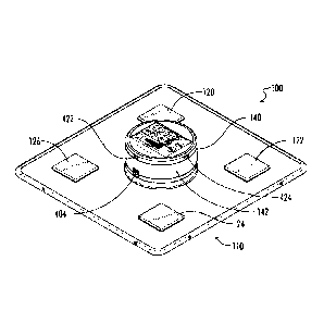
[0012] FIG. 1 illustrates a top perspective view of a vibration and heat
generation
apparatus that can be applied to different locations of body, the apparatus
including a vibration generation mechanism and a heat generation mechanism
housed within a flexible enclosure, the apparatus further including a control
unit
housed within a generally cylindrical enclosure and extending from an upper
flexible
support structure;
Date recue/Date Received 2021-01-20
7
[0013] Fig. 2 illustrates a bottom perspective view of the vibration and heat
generation apparatus of FIG. 1, the view showing the flexible bag-like lower
housing
extending from the upper flexible support structure of FIG. 1;
[0014] FIG. 3 illustrates a top plan view of the vibration and heat generation
apparatus of FIG. 1;
[0015] FIG. 4 illustrates a bottom plan view of the vibration and heat
generation
apparatus of FIG. 1;
[0016] FIG. 5 illustrates a front elevational view of the vibration and heat
generation
apparatus of FIG. 1;
[0017] FIG. 6 illustrates a right side elevational view of the vibration and
heat
generation apparatus of FIG. 1;
[0018] FIG. 7 illustrates an exploded perspective view of the vibration and
heat
generation apparatus of FIG. 1;
[0019] FIG. 8 illustrates a front elevational cross-sectional view of the
vibration and
heat generation apparatus of FIG. 1 taken along the line 8--8 in FIG. 3;
[0020] FIG. 9 illustrates an upper perspective view of one of the four
vibrational pods
of the vibration and heat generation apparatus of FIG. 1;
[0021] FIG. 10 illustrates an exploded perspective view of the vibrational pod
of FIG.
9 showing the upper surfaces of the components;
[0022] FIG. 11 illustrates an exploded perspective view of the vibrational pod
of FIG.
9 with the view of FIG. 10 inverted to show the lower surfaces of the
components;
[0023] FIG. 12 illustrates an upper perspective view of the lower cover of the
vibrational pod of FIG. 9 rotated by a small angle to show addition features
of the
cavity of the lower cover;
[0024] FIG. 13 illustrates an exploded upper perspective view of the heating
pad of
the vibration and heat generation apparatus showing the heating elements, the
temperature sensor and the thermal cutoff switch on the lower sheet of the
heating
pad;
[0025] FIG. 14 illustrates a plan view of the electrical heating wire on the
lower sheet
of the heating pad of FIG. 13;
[0026] FIG. 15 illustrates an exploded upper perspective view of the
cylindrical
control unit of the vibration and heat generation apparatus;
Date recue/Date Received 2021-01-20
8
[0027] FIG. 16 illustrates an exploded perspective view of the cylindrical
control unit
of FIG. 15 with the view of FIG. 15 inverted to show the lower surfaces of the
components of the control unit;
[0028] FIG. 17 illustrates a top plan view of the touch panel control
interface
positioned on the upper end of the cylindrical control unit of FIG. 16;
[0029] FIG. 18 illustrates a block diagram of the electrical and electronic
circuitry of
the vibration and heat generation apparatus of FIG. 1;
[0030] FIG. 19 illustrates an elevational view of the vibration and heat
generation
apparatus of FIG. 1 showing the flexing of the upper support structure and the
bag-
like lower housing to conform the apparatus to a cylindrical object such as a
human
limb;
[0031] FIG. 20 illustrates an elevafional view of a compression wrap
configured to be
attached to a person proximate to the person's hip, the compression wrap
including
a circular bore to receive the control unit of the vibration and heat
generation unit
of FIG. 1;
[0032] FIG. 21 illustrates an elevafional view of a compression wrap
configured to be
attached to a person proximate to the person's knee, the compression wrap
including a circular bore to receive the control unit of the vibration and
heat
generation unit of FIG. 1;
[0033] FIG. 22 illustrates an elevafional view of a compression wrap
configured to be
attached to a person proximate to the person's left shoulder, the compression
wrap
including a circular bore to receive the control unit of the vibration and
heat
generation unit of FIG. 1;
[0034] FIG. 23 illustrates an elevafional view of a compression wrap
configured to be
attached to a person proximate to the person's right shoulder, the compression
wrap including a circular bore to receive the control unit of the vibration
and heat
generation unit of FIG. 1;
[0035] FIG. 24 illustrates an elevafional view of a compression wrap
configured to be
attached to a person proximate to the person's left shoulder, the compression
wrap
including a first circular bore and a second circular bore, each circular bore
configured to receive the control unit of a respective vibration and heat
generation
unit of FIG. 1;
Date recue/Date Received 2021-01-20
9
[0036] FIG. 25 illustrates an elevational view of the compression wrap of FIG.
21 with
the control unit of the vibration and heat generation unit of FIG. 1 extending
through
the circular bore;
[0037] FIG. 26 illustrates a perspective view of the compression wrap and
vibration
and heat generation unit of FIG. 25 secured to a person's knee;
[0038] FIG. 27 illustrates an elevation view of the compression wrap of FIG.
24 with a
control unit of a first vibration and heat generation unit of FIG. 1 extending
through
the first circular bore and with a control unit of a second vibration and heat
generation unit of FIG. 1 extending through the second circular bore;
[0039] FIG. 28 illustrates a front perspective view of the compression wrap
and the
two vibration and heat generation units of FIG. 27 secured to the left
shoulder of a
person, the view showing the first vibration and heat generation unit
positioned
proximate to the front of the person's left shoulder; and
[0040] FIG. 29 illustrates a front perspective view of the compression wrap
and the
two vibration and heat generation units of FIG. 27 secured to the left
shoulder of a
person, the view showing the second vibration and heat generation unit
positioned
proximate to the rear of the person's left shoulder.
Best Mode for Carrying Out The Invention
[0041] A vibration and heat generation apparatus 100 is illustrated in FIGS. 1-
18. As
described below, the vibration and heat generation apparatus can be applied to
different locations of body. The apparatus can apply vibration to a selected
location of the body, can apply heat to the selected location of the body, and
can
apply a combination of vibration and heat to the selected location of the
body.
The apparatus is particularly adapted to be used with compression wraps, which
are
also described below.
[0042] The vibration and heat generation apparatus 100 includes an enclosure
110.
The enclosure comprises a lower bag-like structure 112 that houses an inner
cavity
114 (FIG. 7). The lower bag-like structure is secured to an upper support
structure 116
and extends distally from the upper support structure. In the illustrated
embodiment,
the lower bag-like structure comprises a strong elastomeric fabric such as,
for
example, a polyester-polyurethane copolymer fiber commonly referred to as
spandex. In the illustrated embodiment, the upper support structure comprises
a
Date recue/Date Received 2021-01-20
10
strong, flexible material. For example, the material may be an elastomeric
material
such as neoprene. Other strong, flexible materials can also be used. In the
illustrated embodiment, the upper support structure has a width of
approximately
10.25 inches (approximately 26.1 centimeters), a length of approximately 10.75
inches (approximately 27.3 centimeters) and a thickness of approximately
millimeters.
[0043] In the illustrated embodiment, the lower structure 112 is sewn to the
upper
support structure 116 along the four sides of the upper support structure. The
seam
between the two structures may be reinforced with bias tape 117 or other
material
as shown. In the illustrated embodiment, a zipper 118 is sewn into the lower
structure
to allow selective access to the cavity in the lower structure for initial
installation of
the components described below. The zipper is positioned near one edge of the
lower structure as shown. The zipper is attached in such a manner that the
edges of
the fabric of the lower structure proximate to the two sides of the zipper are
almost
touching to substantially hide the underlying zipper from view. The material
comprising the lower structure has generally rectangular dimensions
sufficiently
larger than the corresponding dimensions of the upper support structure such
that
the lower structure forms the inner cavity 114 with a sufficient depth
relative to the
upper support structure to accommodate a plurality of vibration elements
(e.g., a
first vibration pod 120, a second vibration pod 122, a third vibration pod 124
and a
fourth vibration pod 126). The inner cavity further accommodates at least one
heat
generation unit 130. The heat generator is mechanically and thermally buffered
from the vibration pods by a layer 132 of flexible foam.
[0044] As used herein, "bag-like structure" refers to various shapes the lower
structure
112 may have when in use because the lower structure comprises a fabric
material
that is readily deformable to conform the material to irregular shapes. When
the
lower structure and the upper support structure 116 are resting on a flat
surface, the
lower structure has a selected general shape defined by its outer dimensions
such
that a flexible distal (e.g., lowermost in the illustrated orientation) wall
134 of the
lower structure is generally parallel to the upper support structure. The
actual shape
of the lower structure varies in response to the current shape of the upper
support
structure. For example, when the outer edges of the upper support structure
are
Date recue/Date Received 2021-01-20
11
bent downward, the distal wall of the lower structure may sag away from the
upper
support structure. On the other hand, when the upper support structure is
positioned
on a person's knee or other curved body part, the flexible distal wall of the
lower
structure easily deforms to conform to the irregular curvature of the body
part.
[0045] A control unit 140 extends proximally (e.g., upward in the illustrated
orientation) from a proximal (top) surface of the upper support structure 116.
The
control unit is housed within a generally cylindrical enclosure 142. As shown
in the
exploded view (FIG. 7), the upper support structure includes a though bore 144
that
is positioned close to the center of the upper support structure. The through
bore
has a sufficient size to accommodate a plurality of power wires (e.g., twelve
wires),
which are discussed below. For example, the through bore may have a diameter
between 0.1 inch and 0.25 inch. The control unit together with the enclosure
110,
comprising the upper support structure and the lower structure 112, results in
the
vibration and heat generation apparatus 100 having an overall size and shape
resembling a conventional flattened ice bag.
[0046] As shown in FIG. 7, the through bore 144 in the upper support structure
116 is
surrounded by a plurality of mounting holes 146 formed through the upper
support
structure. For example, five mounting holes are equally spaced about a circle
centered at the center of the upper support structure. In one embodiment, the
circle has a diameter of approximately 3.05 inches. The cylindrical enclosure
has an
annular lower flange 150 that is positioned concentrically with respect to the
cylindrical bore. The lower flange includes a plurality of threaded bores
(e.g., five
bores) 152 (FIG. 16) that are aligned with the mounting holes in the upper
support
structure. An annular compression flange 154 is mounted below the upper
support
structure. The compression flange includes a corresponding plurality of
unthreaded
bores (e.g., five bores) 156 (FIGS. 15 and 16) aligned with the mounting holes
and
aligned with the threaded bores of the annular lower flange. A corresponding
plurality of screws (not shown) pass through the unthreaded bores of the
compression flange and engage the threaded bores of the lower flange. As the
screws are tightened, an annular portion of the upper mounting surface
surrounding
the central cylindrical bore is squeezed between the compression flange and
the
lower flange to secure the cylindrical enclosure to the upper support
structure. It
Date recue/Date Received 2021-01-20
12
should be understood that the screws may be machine screws that engage pre-
threaded bores in the lower flange or may be self-threading screws that create
threads in the bores of the lower flange when the compression flange and the
lower
flange are first interconnected.
[0047] As further shown in FIG. 8, a plurality of electrical wires 160 extend
from the
lower portion of the cylindrical enclosure 142 of the control unit 140 and
through the
through bore 144 (FIG. 7) of the upper support structure 116. Additional
structural
and operational features of the control unit are described below.
[0048] The upper support structure 116 further includes a plurality of pod
mounting
bores 170 that extend through the upper support structure. In the illustrated
embodiment, the upper support structure includes four sets of pod mounting
bores.
Each set of mounting bores comprises four bores arranged in a generally square
pattern with a respective bore at the vertex of the square pattern. For
example, in
one embodiment, the bores in each set of positioned approximately 30
millimeters
(approximately 1.2 inches) apart and have diameters of approximately 5
millimeters
(approximately 0.2 inch). In the illustrated embodiment, each set of pod
mounting
bores is centered at selected distances from the center of the upper support
structure. For example, the center of a rear left set is positioned
approximately
2.85 inches to the left of the center of the upper support structure and
approximately 2.85 inches toward the rear relative to the center of the upper
support structure. In the illustrated embodiment, the sets of pod mounting
bores are
positioned substantially symmetrically with respect to the center of the upper
support structure such that the center of each set is approximately the same
distance from the center of the upper support structure. In other embodiments,
the
sets of mounting bores may be positioned differently from front to rear than
from left
to right, particularly if the upper support structure has a non-square upper
surface.
Note that as used herein, left and right, front and rear, and top and bottom
are used
to indicate positions relative to the drawings with the exposed upper surface
of the
upper support structure designated as the "top" or "proximal" surface. The
apparatus may be used in many different orientations wherein the upper surface
of
the upper support structure may be oriented outward, downward or the like.
Date recue/Date Received 2021-01-20
13
[0049] The first vibration pod 120 is shown in more detail in FIGS. 9-11. The
other three
vibration pods 122, 124, 126 are identical or are substantially identical. The
first
vibration pod includes an upper cover 180. In the illustrated embodiment, a
top
surface 182 of the upper cover is square or substantially square with each
side of the
square having a length of approximately 45 millimeters). The upper cover has a
thickness of approximately 4.25 millimeters to a lower surface 184. Four
protrusions
186 extend from the lower surface of the upper cover. Each protrusion has a
diameter selected such that each protrusion fits through a selected one of the
mounting bores 170 in the rear left set of mounting bores. For example, in the
illustrated embodiment, the protrusions have a diameter of approximately
millimeters. Each protrusion has a length of approximately 16.5 millimeters.
The
end of each protrusion opposite the top of the upper cover has a central bore
188
that may be threaded to receive a machine screw (not shown). Alternatively,
the
central bore may be threadable to receive a self-taping screw.
[0050] The first vibration pod 120 includes a lower cover 200 having a central
cavity
202. The lower cover has a generally square upper surface 204 surrounding the
central cavity. In the illustrated embodiment, the peripheral dimensions of
the upper
surface of the lower cover generally correspond to the peripheral dimensions
of the
upper cover 180. The lower cover has an arcuate lower surface having four
through
bores 206 formed therein. The through bores are spaced apart by distances
corresponding to the spacing of the protrusions 186 of the upper cover 180.
The
through bores are counterbored with respect to the lower cover to receive the
heads of the screws (not shown) that secure the lower cover to the upper
cover.
[0051] A lower inner surface 210 of the lower cover 200 corresponds to the
lower
surface of the central cavity 202. Each of the through bores 206 is surrounded
by a
respective inner protrusion 212 that extends from the lower inner surface of
the
central cavity. The top surface of each inner protrusion has a respective
counterbore 214 that surrounds the through bore and extends a selected
distance
into the protrusion. The diameter of each counterbore is selected to
correspond to
the outer diameter of the protrusions 186 extending from the top cover 180
(e.g.,
approximately 5 millimeters in the illustrated embodiment) so that each
protrusion of
the top cover fits snugly into the respective counterbore of one of the inner
Date recue/Date Received 2021-01-20
14
protrusions of the lower cover. The depth of the counterbore in each inner
protrusion in the central cavity is selected such that when the protrusions of
the top
cover are engaged with the counterbores, the lower surface 184 of the top
cover is
spaced apart from the upper surface 204 of the bottom cover by a distance less
than the thickness of the upper support structure 116. For example, in the
illustrated
embodiment, the two surfaces are spaced apart by approximately 1.85
millimeters,
which is substantially less than the thickness (e.g., approximately 5
millimeters) of the
upper support structure. Thus, when the top cover is secured to the bottom
cover by
the four screws (not shown) passing through the through bores 206 of the lower
cover and engaging the central bores 188 of protrusions extending from the
upper
cover, the portions of the upper support structure in contact with the upper
cover
and the lower cover are squeezed between the two covers to secure the first
vibration pod 120 to the upper support structure. The other three vibration
pods 122,
124, 126 are secured to the upper support structure in a like manner.
[0052] The lower inner surface 210 of the lower cover 200 includes a first
motor
bearing support 230 and a second motor bearing support 232. Each motor bearing
support is sized and positioned to receive a respective motor bearing as
described
below. The lower inner surface further includes three raised ribs 234
positioned
between the first and second bearing supports. Each rib has a respective upper
surface positioned a selected distance from the lower inner surface.
[0053] The first bearing support 230 includes a generally semicircular upper
surface
sized to receive a front bearing 242 of a motor 240. The second bearing
support 232
includes a generally semicircular upper surface sized to receive a rear
bearing 244
of the motor. The motor has a generally horizontal lower surface 246 that
rests on
the three raised ribs 234 when the bearings of the motor are positioned in the
respective bearing supports. The motor also has a generally horizontal upper
surface 248, which is parallel to the upper surface in the illustrated
embodiment. The
motor includes a shaft 250. A front portion of the shaft extends from the
front
bearing to support an eccentric mass 252. The eccentric mass is positioned
within
an unobstructed portion of the inner cavity and is able to move freely within
the
portion of the cavity when the shaft of the motor is rotated.
Date recue/Date Received 2021-01-20
15
[0054] The lower cover 200 further includes a motor clamp plate 260 having an
upper surface 262 and a lower surface 264. The motor clamp plate rests upon
four
clamp plate support protrusions 270 that extend upward from the lower inner
surface 210. Each clamp plate support protrusion has a respective central bore
272.
Each central bore may be threaded to receive the threads of a machine screw
(not
shown). Alternatively, each central bore may be threadable by a self-tapping
screw.
[0055] The motor clamp plate 260 is sized to fit within the lower cover 200
and to rest
upon the clamp plate support protrusions 270. The motor clamp plate includes
four
plate mounting through bores 280 that are aligned with the central bores of
the
clamp plate support protrusions. Each plate mounting through bore is
counterbored
on the upper surface 262 of the motor clamp plate so that the heads of the
machine (or self-tapping) screws (not shown) do not extend above the upper
surface of the motor clamp plate.
[0056] The lower surface 264 of the motor clamp plate 260 includes a
respective
protrusion 282 surrounding each plate mounting through bore 280. Each
protrusion
extends a short distance (e.g., approximately 2 millimeters; approximately
0.08 inch)
below the lower surface. Each protrusion is counterbored to have an inside
diameter corresponding to the outside diameter of a clamp plate support
protrusion
270 (e.g., approximately 2.3 millimeters; approximately 0.09 inch in the
illustrated
embodiment). Thus, when the motor clamp plate is secured to the clamp plate
protrusions, the motor clamp plate cannot shift laterally with respect to the
lower
cover.
[0057] The motor clamp plate 260 further includes four clearance through bores
284,
which are positioned and sized to provide clearance for the four protrusions
186 that
extend from the lower surface 184 of the upper cover 180. For example, in the
illustrated embodiment, the clearance through bores have diameters of slightly
greater than approximately 5 millimeters (approximately 0.2 inch) to provide a
snug
fit with respect to the protrusions.
[0058] The motor clamp plate 260 includes two motor engagement ribs 290 that
extend from the lower surface 264. The engagement ribs are positioned to
engage
the generally horizontal upper surface 248 of the motor 240 when the motor
clamp
Date recue/Date Received 2021-01-20
16
plate is positioned on the lower cover 200 of the first vibration pod 120. The
thickness
of each rib with respect to the lower surface of the motor clamp plate is
selected
such that when the motor clamp plate is fully secured by the four screws (not
shown), the ribs are pressed against the horizontal upper surface of the
motor.
Accordingly, the motor is tightly secured between the ribs of the motor clamp
plate
and the three raised ribs 234 of the lower inner surface 210 of the lower
cover 200.
[0059] In the illustrated embodiment, the motor 240 comprises a permanent
magnet
DC motor operating at approximately 5,300 revolutions per minute (RPM) from a
12-
volt DC supply. In one embodiment, the motor comprises an FC130 style motor,
which is commercially available from a number of sources. The motor draws
approximately 0.09 Amperes at the rated RPM.
[0060] The motor 240 and the eccentric mass 252 together have an overall
length of
approximately 38 millimeters. The motor has an overall diameter of
approximately
20.2 millimeters and is flattened to space the lower surface 246 and the upper
surface 248 apart by approximately 15.4 millimeters.
[0061] The eccentric mass 252 is substantially cylindrical. The eccentric mass
has an
overall diameter of approximately 10 millimeters, and has a length along the
shaft of
the motor of approximately 7 millimeters. In the illustrated embodiment, the
mass
comprises powdered metal (e.g., iron), which is compacted to have a mass
(weight) of approximately 3.5 grams. The eccentric mass is mounted on the
shaft
250 of the motor 240 via a shaft bore 254 having a diameter of approximately
2.1
millimeters. In the illustrated embodiment, the shaft bore is offset from the
center of
the eccentric mass by approximately 2.2 millimeters to cause the mass to
impart a
vibration. The vibration is communicated from the shaft of the motor and
through
the bearings 242, 244 to bearing supports 230, 232 to cause the lower cover
200 of
the vibration pod 120 to vibrate.
[0062] Each of the four vibration pods 120, 122, 124, 126 are electrically
connected
to the control unit as described below.
[0063] As illustrated in FIG. 14, in the illustrated embodiment, the heat
generation unit
130 comprises a first (lower) rectangular sheet of cloth 330 and a second
(upper)
rectangular sheet of cloth 332. Each sheet has outer dimensions of
approximately
250 millimeters by approximately 200 millimeters. In the illustrated
embodiment,
Date recue/Date Received 2021-01-20
17
each sheet comprises a 200g needle punch material (i.e., non-woven material
formed by a conventional needle punching process) having a thickness of
approximately 1.5 millimeters. The material has a density of approximately 200
grams per square meter. At least one electrical resistance wire is positioned
between the two sheets. In the illustrated embodiment, a first resistance wire
334
and a second resistance wire 336 are secured to the upper surface of the lower
sheet by lock stitching (not shown) in a conventional manner. The resistance
wires
can also be secured to the upper sheet in a similar manner. In one embodiment,
each resistance wire comprises a thin, flat resistance wire, such as, for
example, a
commercially available titanium resistance wire. In the illustrated
embodiment, the
cross-sectional dimensions of the resistance wires are selected to provide a
resistance of approximately 16 ohms per meter. Each resistance wire has a
length of
approximately 1.25 meters such that each wire has a total resistance of
approximately 20 ohms.
[0064] The two resistance wires 334, 336 form two maze-like patterns, which
are
substantially symmetric about a centerline 340 of the lower sheet 330. Each
resistance wire extends from a first common terminal 342 to a second common
terminal 344 such that the two segments are connected in parallel. The first
common terminal of the resistance wires is connected directly to a first
supply
wire 346. The second common terminal of the resistance wires is connected to a
second supply wire 348 via a thermal cutoff switch 350. The thermal cutoff
switch
has a first terminal 352 connected to the second common terminal of the
resistance
wires and has a second terminal 354 connected to the second supply wire via a
connector 356.
[0065] The thermal cutoff switch 350 is normally closed such that the control
unit 140
is electrically connected to the second common terminal 344 of the resistance
wires 334, 336. The first common terminal 342 of the resistance wires is
always
connected to the control unit. Thus, current is conducted from the first
terminal
around each of the first resistance wire and the second resistance wire in
parallel.
Since each resistance wire has a resistance of approximately 20 ohms, each
resistance wire generates approximately 14 watts of heat at a voltage of
Date recue/Date Received 2021-01-20
18
approximately 16.8 volts. The two resistance wires generate a total of
approximately
28 watts of heat.
[0066] The thermal cutoff switch 350 is set to open the circuit when the
temperature
proximate to the thermal cutoff switch exceeds approximately 80 degrees
Celsius
+/-5 degrees and to stay open until the temperature reduces to approximately
55
degrees Celsius +/-10 degrees. In one embodiment, the thermal cutoff switch
comprises a KLS-KSD9700 thermal fuse commercially available from Ningbo KLS
Imp
& Exp Co. Ltd. In Beilun Ningbo Zhejiang China. The thermal cutoff switch is
positioned across portions of the heating wire such that the thermal cutoff
switch
directly senses the temperature of the heating wire and disconnects the
electrical
path well before the heat from the heating wire is communicated though the
lower
sheet and the material of the lower structure 112 to a user (not shown).
[0067] As further shown in FIGS. 14 and 15, a thermistor 360 is secured to the
first
(lower) sheet of cloth 330. The thermistor is also positioned near the center
of the first
sheet; however, the thermistor is positioned between two adjacent segments of
the
first resistance wire 334 rather than directly on the resistance wire. A first
wire 362
and a second wire 364 extend from the thermistor and are connected to the
control
unit 140. In one embodiment, the thermistor is a negative temperature
coefficient
(NTC) thermistor. For example, the thermistor may be an MF52-104F-3950-600L
thermistor commercially available from Dongguan Xinxiang Electronic Technology
Co., Ltd., in China. The thermistor has a resistance that varies over a wide
temperature range. For example, at 55 degrees Celsius, the thermistor has a
resistance of approximately 29,733 ohms; at 60 degrees Celsius, the thermistor
has a
resistance of approximately 24,753 ohms; and at 71 degrees Celsius, the
thermistor
has a resistance of approximately 16,794 ohms. The resistance of the
thermistor is
readily detectable in a conventional manner to determine when the temperature
of
the thermistor exceeds a selected temperature.
[0068] After the thermal cutoff switch 350 and the thermistor 360 are
positioned on
the first (lower) sheet 330, and after the first common terminal 342 is
connected to
the first supply wire 346 and the second common terminal 344 is connected to a
second supply wire 348, the second (upper) sheet 332 is secured to the first
sheet. In
Date recue/Date Received 2021-01-20
19
the illustrated embodiment, the lower surface of the second sheet includes an
adhesive to removably attach the second sheet to the first sheet.
[0069] As further shown in FIGS. 7 and 8, the layer 132 of flexible foam is
positioned
above the second (upper) sheet 332 between the second sheet and the vibration
pods 120, 122, 124, 126 to partially buffer the vibrations provided by the
vibration
pods when operated as described below.
[0070] The structure of the control unit 140 is shown in more detail in FIGS.
15 and 16.
As described above, the control unit includes the lower flange 150 and the
removably attachable annular compression flange 154. The lower flange is
connected to a lower body portion 400 of the control unit. The lower body
portion
supports a first printed circuit board (PCB) 402.
[0071] The first PCB 402 includes an electrically and mechanically attached
conventional charging jack 404, which extends through a notch in the wall of
the
lower body portion. The
first PCB also includes a plurality of metal oxide
semiconductor field effect transistors (MOSFETs) (not shown) that provide
power to
the vibration pods 120, 122, 124, 126 and to the heat generation unit 130 via
a
plurality of connectors 406. A lithium polymer (LiPo) battery 408 rests upon
the first
PCB and is electrically connected to the first PCB to receive charging energy
via the
first PCB and to provide operational energy to the other components of the
control
unit. The lower body portion includes a central opening to allow wiring from
the
connectors to the vibration pods 120, 122, 124, 126 and to the heat generation
unit 130 to pass therethrough.
[0072] A cylindrical middle body portion 410 is positioned over the first PCB
402 and
the LiPo battery 408 and is secured to the lower body portion. A lower end 412
of
the middle body portion is open. An upper end 414 of the middle body portion
is
generally closed; however, the upper end includes a plurality of through
passages
to allow wiring to pass through the upper end from the first PCB to a second
PCB
420. The middle body portion also includes a notch to accommodate the charging
jack 404.
[0073] The second PCB 420 rests on the upper end 414 of the middle body
portion
410 and is secured to the upper end by suitable fasteners (not shown). The
second
PCB is electrically connected to the first PCB 402 via a plurality of wires
(not shown).
Date recue/Date Received 2021-01-20
20
The second PCB receives power from the battery 406 via the first PCB 402. The
second PCB also receives input power from the power input jack 404. The second
PCB generates a battery charging voltage of approximately 16.8 volts, which is
provided to the battery via the first PCB. The second PCB also generates a
motor
voltage of approximately 12 volts, which is provided to the first PCB as a
motor
driving voltage. The second PCB generates control signals to control the power
applied to the vibration pods 120, 122, 124, 126 and to the heat generation
unit 130.
The control signals are applied to the MOSFETs (not shown) on the first PCB.
[0074] The second PCB 420 communicates with a liquid crystal display (LCD)
panel
and a touch panel (described below). The second PCB is electrically connected
to
a first pushbutton switch 422 and to a second pushbutton switch 424. The two
switches are mounted on the printed circuit board in the illustrated
embodiment.
The first pushbutton switch is manually operable to turn the vibration and
heat
generation apparatus 100 on and off. The second pushbutton switch is manually
operable to select between two brightness levels for the LCD display. Each
brightness level corresponds to a respective operational mode for the touch
panel.
The electronic circuitry on the second PCB and the two operational modes are
described in more detail below.
[0075] An LCD panel 430 is positioned proximate to and electrically connected
to
the second PCB 420. For example, the LCD panel may be a "daughter board"
mechanically connected to the second PCB via a connector (not shown). The LCD
panel may also be connected to the second PCB via a plurality of electrical
wires
(not shown). The LCD panel is responsive to signals from the second PCB to
generate signals to cause images to be displayed as described below.
[0076] A generally transparent touch panel 440 is positioned over the LCD
panel 430.
The touch panel generates signals resulting from manual manipulation of
selected
portions of the touch panel. The signals are provided to the second PCB. In
certain
embodiments, the LCD panel and the touch panel are provided in combination as
a single integrated package. Such combinations are commercially available and
are well understood. In the illustrated embodiment, the LCD panel and the
display
panel comprise a Model No. YH26167VNT display commercially available from
Dongguan Quinniahong Electronic Technology Co., Ltd., in China.
Date recue/Date Received 2021-01-20
21
[0077] An upper body portion 450 is positioned over the LCD panel 430, the
touch
panel 440 and the second PCB 420. A middle section of the upper body portion
is
removed to expose the LCD touch panel such that the images displayed on the
LCD touch panel are visible to a user and such that a user can access the
surface of
the LCD touch panel with the user's fingertips or with a suitable stylus. In
the
illustrated embodiment, a bezel 452 is positioned over the upper body portion
to
frame the active portions of the LCD panel and the touch panel.
[0078] As shown in FIG. 17, the upper end of the control unit 140 comprises
the LCD
panel 430 and the overlying touch panel 440. The LCD panel displays a
plurality of
icons to convey information to a user regarding the operational mode of the
vibration and heat generation apparatus 100 and to indicate to a user where to
touch the touch panel to control the operation of the vibration and heat
generation
apparatus.
[0079] In the illustrated embodiment, a right hand portion of the LCD panel
430
displays a "Start" icon 550 and a "Stop" icon 552. Each icon represents a
respective
touch active portion of the overlying touch panel 440 such that touching the
area of
the "Start" icon activates the vibration and heat generation apparatus and
touching the area of the "Stop" icon deactivates the vibration and heat
generation
apparatus. Although the vibration and heat generation apparatus is
deactivated,
the power remains on to provide an active display until the first pushbutton
switch is
pushed to turn off the power. When the Start icon is touched to activate the
apparatus, the display brightens (temporarily) to indicate that the apparatus
is
active.
[0080] The LCD panel 430 further displays a temperature icon 560 (represented
by a
thermometer symbol and the underlying letters "Temp." Three temperature
selection icons are aligned with the temperature icon. Each temperature
selection
icon corresponds to a touch active area of the overlying touch panel 440. A
first
temperature selection icon 562 is labeled with "1" and is further identified
with
"Low." A second temperature selection icon 564 is labeled with "2" and is
further
identified with "Med." A third temperature selection icon 566 is labeled with
"3" and
is further identified with High."
Date recue/Date Received 2021-01-20
22
[0081] When the control unit 140 is first turned on and the start icon 550 is
touched,
no heating mode is selected. Touching the area of the first temperature
selection
icon 562 activates the "Low" heat mode icon and selects a temperature setting
of
approximately 42 degrees Celsius (approximately 108 degrees Fahrenheit). A
ring
around the first temperature selection icon is illuminated on the underlying
LCD
panel 430 to indicate that the low temperature range is selected. Touching the
area of the first temperature selection icon when the ring is illuminated
turns off the
low heat mode.
[0082] Touching the area of the second temperature selection icon 564
activates
the "Med" heat mode icon and selects a temperature setting of approximately
50 degrees Celsius (approximately 122 degrees Fahrenheit). A ring around the
second temperature selection icon is illuminated on the underlying LCD panel
430 to
indicate that the medium temperature range is selected. Touching the area of
the
second temperature selection icon when the ring is illuminated turns off the
medium
heat mode.
[0083] Touching the area of the third temperature selection icon 566 activates
the
"High" heat mode icon and selects a temperature setting of approximately 60
degrees Celsius (approximately 140 degrees Fahrenheit). A ring around the
third
temperature selection icon is illuminated on the underlying LCD panel 430 to
indicate that the high temperature range is selected. Touching the area of the
third
temperature selection icon when the ring is illuminated turns off the high
heat mode.
[0084] Touching the stop icon area of the touch panel 440 clears any selected
temperature selection.
[0085] In operation, the control unit 140 monitors the resistance of the
thermistor 360
and turns the heat generation unit 130 off and on based on the resistance. For
example, when the "Low" heat setting is selected, the control unit detects
when the
thermistor becomes sufficiently hot (e.g., approximately 42 degrees Celsius)
such
that the resistance of the thermistor decreases below approximately 48,900
ohms.
The control unit turns the heat generation unit off. The control unit
continues to
monitor the resistance of the thermistor while the thermistor cools and the
resistance
of the thermistor increases. When the thermistor is sufficiently cool (e.g.,
at a
temperature below approximately 37 degrees Celsius) and the resistance of the
Date recue/Date Received 2021-01-20
23
thermistor increases above approximately 59,900 ohms, the heat generation unit
is
turned back on. The control unit operates in a similar manner for the other
two
temperature settings. For example, when the "Med" heat setting is selected,
the
control unit turns off the heat generation unit when the resistance of the
thermistor
decreases below approximately 35,900 ohms (corresponding to a temperature of
approximately 50 degrees Celsius) and turns the heat generation unit back on
when
the resistance of the thermistor increases above approximately 48,900 ohms
(corresponding to a temperature of approximately 42 degrees Celsius. When the
"High" heat setting is selected, the control unit turns off the heat
generation unit
when the resistance of the thermistor decreases below approximately 24,750
ohms
(corresponding to a temperature of approximately 60 degrees Celsius) and turns
the
heat generation unit back on when the resistance of the thermistor increases
to
above approximately 32,000 ohms (corresponding to a temperature below
approximately 53 degrees Celsius).
[0086] The LCD panel 430 further displays a vibration selection icon 570
(represented
by a waveform symbol and the underlying word "Vibration." Three vibration
selection icons are aligned with the vibration icon. Each vibration selection
icon
corresponds to a touch active area of the overlying touch panel 440. A first
vibration selection icon 572 is labeled with a first waveform icon and is
further
identified with "Wave." A second vibration selection icon 574 is labeled with
a
second waveform icon and is further identified with "Pulse." A third vibration
selection icon 576 is labeled with a third waveform icon and is further
identified with
"Constant."
[0087] In the illustrated embodiment, when the control unit 140 is first
turned on and
the start icon 550 is touched, no vibration mode is selected. Touching the
area of
the first vibration selection icon 572 activates the wave vibration mode in
which the
four vibration pods 120, 122, 124, 126 are turned on in a selected sequence. A
ring
around the first vibration selection icon is illuminated on the underlying LCD
panel
430 to indicate that the wave vibration mode is selected. In one embodiment,
the
selected sequence of the wave vibration mode comprises turning on the first
vibration pod for approximately one-quarter second; then turning off the first
vibration pod and turning on the second vibration pod for approximately one-
Date recue/Date Received 2021-01-20
24
quarter second; then turning off the second vibration pod and turning on the
third
vibration pod for approximately one-quarter second; then turning off the third
vibration pod and turning on the fourth vibration pod for approximately one-
quarter
second. The next sequence is started by turning off the fourth vibration pod
and
turning on the first vibration pod for approximately one-quarter second and
repeating the foregoing steps. Rather than repeating the same sequence,
subsequent sequences may turn the vibration pods on and off in a different
order.
Multiple vibration pods may also be turned on at the same time. The sequence
or
sequences are repeated as long as the control unit remains in the wave
vibration
mode. Touching the area of the first vibration selection icon when the ring is
illuminated turns off the wave vibration mode.
[0088] Touching the area of the second vibration selection icon 574 activates
the
pulse vibration mode icon 574. A ring around the second vibration selection
icon is
illuminated on the underlying LCD panel 430 to indicate that the pulse
vibration
mode is selected. In one embodiment, in the pulse vibration mode, the four
vibration pods 120, 122, 124, 126 are turned on at the same time for a
predetermined duration (e.g., approximately one-half second), and then turned
off
at the same time for a predetermined duration (e.g., approximately one-half
second). The sequence of all on" followed by all off" is repeated as long as
the
control unit remains in the pulse vibration mode. Touching the area of the
second
vibration selection icon when the ring is illuminated turns off the pulse
vibration
mode.
[0089] Touching the area of the third vibration selection icon 576 activates
the
constant vibration mode icon 576. A ring around the third vibration selection
icon is
illuminated on the underlying LCD panel 430 to indicate that the constant
vibration
mode is selected. In one embodiment, the four vibration pods 120, 122, 124,
126 are
operated continuously as long as the constant vibration mode is selected.
Touching
the area of the third vibration selection icon when the ring is illuminated
turns off the
constant vibration mode.
[0090] Touching the stop icon 552 turns off the currently selected temperature
mode
and the currently selected vibration mode.
Date recue/Date Received 2021-01-20
25
[0091] Any of the three vibration modes can be selected in combination with
any of
the three heat modes. Furthermore, a vibration mode may be selected without
selecting a heat mode; and a heat mode may be selected without selecting a
vibration mode.
[0092] The display panel 430 further displays a timer icon 580 represented by
a solid
circle and the underlying word "Timer." The timer icon is aligned with a
sequence of
vertical timer bar icons 582 with increasing heights. Each timer bar icon
represents an amount of time for which the vibration and heating apparatus 100
operates at the current vibration mode and heat mode settings before turning
off
automatically. For example, each timer bar icon may represent 2 minutes of
remaining time such that when all bars are active, approximately 20 minutes of
time
remains before the apparatus turns off automatically. The tallest (right-most)
timer
bar is turned off at the end of approximately 2 minutes to indicate that only
approximately 18 minutes remain. Each timer bar is sequentially turned off in
similar
intervals until the shortest (left-most) timer bar is turned off and the
overall operation
of the vibration and heat generation apparatus is stopped. The area of the
timer
bars is touch active such that any portion of the area of the timer bars can
be
touched at any time to reset the timer to the full twenty minutes. The timer
bars are
deactivated by touching the "Stop" icon 552. Touching the "Start" icon 550
restarts
the timer at 20 minutes (all timer bars illuminated).
[0093] Although not part of either the LCD panel 430 or the touch panel 440, a
plurality of display ports 590 (e.g., five display ports) are formed in the
bezel 450. The
display ports are aligned with a corresponding plurality of light emitting
diodes (LEDs)
592 on the second PCB 420. The five LEDs are selectively illuminated to
indicate the
current charge on the LiPo battery 408. For example, all five LEDs are
illuminated to
indicate a fully charged battery. One LED at a time is turned off as the
charge of
the battery decreases. The last illuminated LED may be illuminated in a
different
color (e.g., red versus green) to indicate that the battery needs to be
recharged.
[0094] The control unit 140 further includes the first conventional pushbutton
switch 422 located on the perimeter of the control unit just below the LCD
display
430 and touch panel 440 and facing the front of the vibration and heat
generation
apparatus 100. The first pushbutton switch operates as a master on/off switch
to
Date recue/Date Received 2021-01-20
26
enable a user to operate the switch to turn the vibration and heat generation
apparatus off to conserve the energy stored in the battery. The user operates
the
first pushbutton switch to turn the vibration and heat generation apparatus on
such
that the LCD display and the touch panel are activated to respond to touch
commands as described above. The control unit further includes the second
conventional pushbutton switch 424 located on the perimeter of the control
unit just
below the LCD panel and the touch panel and facing the right of the vibration
and
heat generation apparatus. The second pushbutton switch provides a signal to
the
control unit to selectively dim the LCD panel to reduce energy consumption
when
full brightness is not required. The activation of the second pushbutton
switch also
disables the touch panel from being responsive to touching by a user. Thus,
any
inadvertent touching of the touch panel will not change the mode of operation
of
the vibration and heat generation apparatus. In the illustrated embodiment,
the
LCD panel is automatically dimmed and the touch panel is automatically
disabled
after a short period of no touching by the user. For example, the LCD panel is
dimmed and the touch panel is disabled after approximately 5 seconds of no
touching by the user.
[0095] FIG. 18 illustrates a block diagram 600 of the electrical circuitry of
the vibration
and heat generation apparatus 100. In FIG. 18, previously identified
components
are numbered as before. The first PCB 402 and the second PCB 420 are
illustrated in
dashed lines to encompass the components on each PCB. The locations of the
various components can vary in other embodiments. For example, the LiPo
battery
408 and the charging jack 404 are shown as being part of the first PCB as
described
above. In the illustrated embodiment, the first PCB includes a heater driver
610 and
motor drivers 612. In the illustrated embodiment, the heater driver and each
of the
four motor drivers comprises a power MOSFET that provides a current return
path to
ground when the respective driver is activated. In the illustrated embodiment,
the
battery LiPo battery is charged by a battery charger circuit 620, which is
located on
the second PCB. The battery charger circuit receives power from a conventional
wall adapter (not shown) and charges the LiPo battery to approximately 16.8
volts.
A second power control circuit ("motor voltage generator") 622 converts the
battery voltage to approximately volts to drive the vibration motors 120, 122,
124,
Date recue/Date Received 2021-01-20
27
126. In the illustrated embodiment, the motor voltage generator is also
located on
the second PCB. Although not shown in FIG. 18, the second PCB also includes
circuitry to convert the battery voltage a supply voltage for the digital
electronics
circuitry. For example, a conventional 5-volt three-terminal voltage regulator
(e.g., a
Holtek HT7550-1) is suitable.
[0096] The second PCB 420 includes a microcontroller 630 that controls the
operation of the other components on the second PCB and the first PCB 402. For
example, the microcontroller in the illustrated embodiment is a commercially
available 44-pin microcontroller that runs a conventional 8051 instruction
set. One
such microcontroller is an SN8F5707 microcontroller from Sonix in Taiwan. The
microcontroller generates control signals to and receives feedback signals
from the
battery charger circuit 620 to control the charging of the LiPo battery 408.
The
microcontroller also controls the operation of the motor voltage generator 622
in a
similar manner. The microcontroller controls the heater driver 610 and the
motor
drivers 612 in response to commands received from a user. The microcontroller
monitors a voltage responsive to the resistance of the thermistor 360 and
selectively
turns on and turns off the heater driver to maintain the temperature of the
heat
generation unit 130 within a selected temperature range.
[0097] The microcontroller 630 also controls the information displayed on the
LCD
panel 430 via a display controller 640. The microcontroller sends signals to
the
display controller representing the information to be displayed. The
display
controller receives the signals and generates the required command and data
signals to the LCD to properly display the information. As discussed above,
the
displayed information includes the start and stop icons, the temperature icon
with
the three level icons, the vibration icon with the three vibration mode icons,
and the
timer icon with the 10 time bars. The control of an LCD is well-known in the
art and is
not described in detail herein. In the illustrated embodiment, the display
controller is
incorporated into the microcontroller. In other embodiments, the display
controller
may be a separate controller.
[0098] The microcontroller 630 receives signals from the touch panel 440 via a
touch
panel controller 650, which is located on the second PCB 420 in the
illustrated
embodiment. In the illustrated embodiment, the microcontroller communicates
with
Date recue/Date Received 2021-01-20
28
the touch panel controller via a conventional I2C bus. The microcontroller is
responsive to signals from the touch panel controller that represent touching
of the
touch panel in areas corresponding to the icons displayed on the underlying
LCD
panel 430. The microcontroller is not responsive to touching of areas of the
touch
panel that do not correspond to a displayed icon. In the illustrated
embodiment,
the touch panel controller comprises a YS812A touch sensing microcontroller,
which
is commercially available from Taiwan Hui Electronics Co., Ltd., in Taiwan.
[0099] As discussed above, the microcontroller 630 is also responsive to the
first
pushbutton switch 422 and the second pushbutton switch 424. When the
microcontroller is off and the first pushbutton switch is activated, the
microcontroller
awakens from a low power mode and generates the signals required to display
the
icons on the LCD panel 430. The microcontroller waits for signals from the
touch
panel 440 via the touch panel controller 650. If a
touch signal is received
corresponding to the location of the start icon, the microcontroller becomes
responsive to the touch signals from the heat selection icons and the
vibration
selection icons as described above. When the first pushbutton switch is
activated
while the microcontroller is active, the microcontroller turns off all
functions and
reenters the low-power state.
[00100]The microcontroller 630 is also responsive to the second pushbutton
switch
424. Each time the second pushbutton switch is activated, the main controller
toggles between a first display state and a second display state. In the first
display
state, the microcontroller sends a command to reduce the brightness of the LCD
panel 430. In the first display state, the microcontroller is not responsive
to any touch
signals from the touch panel 440 via the touch panel controller 650. When the
second pushbutton switch is activated when the microcontroller is in the first
display
state, the microcontroller responds by switching to the second display state
wherein
the microcontroller sends a command to increase the brightness of the icons of
the
LCD panel. While in the second display state, the microcontroller is
responsive to
touch signals from the touch panel via the touch panel controller. In the
illustrated
embodiment, the microcontroller automatically reenters the first display state
after a
selected period of inactivity (e.g., approximately 5 seconds) when the user
does not
touch an active portion of the touch panel. In the first display state, the
reduction in
Date recue/Date Received 2021-01-20
29
brightness of the LCD saves energy; and the microcontroller is not responsive
to any
inadvertent touching of the touch panel.
[00101]The microcontroller 630 further sends commands to the LCD panel 430 to
cause the LCD panel to display selected graphics as described above. In
addition
to sending commands to generate the static display icons shown in FIG. 17, the
microcontroller also sends commands to selectively illuminate the ring icons
that
represent the current selected operational state (e.g., temperature setting
low,
medium or high; and vibration setting wave, pulse or constant). The
microcontroller
also updates the timer bar icons to display the remaining time before the
microcontroller automatically turns off.
[00102] The microcontroller 630 receives commands from the touch panel 440 via
the
touch panel controller 650 when a user touches an active area of the touch
panel.
The microcontroller is responsive to the received commands to selectively
control
the operations of the four vibration pods 120, 122, 124, 126 and to control
the
operation of the heat generation unit 130.
[00103] The microcontroller 630 controls the first vibration pod 120 by
selectively
providing the motor voltage (e.g., approximately 12 volts DC) to the first
vibration
pod. In the illustrated embodiment, the microcontroller activates one or more
of the
motor drivers 612 to provide respective return paths to ground. The other
three
vibration pods 122, 124, 126 are controlled in a similar manner. The
microcontroller
controls the heat generation unit 130 by selectively providing the battery
voltage
(e.g., approximately 16.8 volts DC) to the heat generation unit. In the
illustrated
embodiment, the microcontroller activates the heater driver 610 to provide a
return
path to ground. The microcontroller is responsive to the resistance of the
thermistor
360 to maintain the temperature within a range selected by the currently
active
temperature mode. As noted above, the thermal cutoff switch 350 embedded in
the heat generation unit independently opens the current path to the heat
generation unit if the temperature of the heat generation unit exceeds
approximately 80 degrees Celsius.
[00104] As further shown in FIG. 18, the vibration and heat generation
apparatus 100
may also be controlled by a Bluetooth interface 660 coupled to a smartphone
(not
shown) or other device having a Bluetooth compatible interface. For example,
in
Date recue/Date Received 2021-01-20
30
one embodiment, the Bluetooth interface is connected to the microcontroller
630 to
send commands to and to receive information from the microcontroller. The
Bluetooth interface is controlled by an application (App) running on the
smartphone
(or other device) that presents a user with a display screen having icons
corresponding to the icons shown in FIG. 17. When a user touches the icons on
the
smartphone display, the commands are sent to the microcontroller via the
coupled
Bluetooth interfaces to control the microcontroller in a manner corresponding
to the
control of the microcontroller by the touch panel controller 650. The
microcontroller
responds by selecting the requested mode and by sending a confirmation to the
smartphone App that the command has been received and has been
implemented on the vibration and heat generation apparatus. The Bluetooth
interface is particularly useful when the vibration and heat generation unit
is
positioned on a user's body in a location where the LCD display 430 is not
easily
viewed by the user.
[00105] As shown in FIG. 19, the vibration and heat generation apparatus 100
is
sufficiently flexible to bend around a generally cylindrical object 670 such
as, for
example, a human limb or joint (represented in dashed lines). The flexible
lower
bag-like structure 112 readily conforms to the contours of the limb or joint.
The upper
support structure 116 forms the outer boundary of the bent apparatus and
positions
the vibration pods and heat generating unit (within the enclosure 110) against
the
joint or limb receiving therapy. In addition to having an overall size and
shape
resembling a conventional flattened ice bag, the vibration and heat generation
apparatus conforms to a human body part in a manner similar to an ice bag.
[00106] The vibration and heat generation apparatus 100 disclosed herein is
configured for use with compression wraps that are used to apply compression
to an
ice bag positioned against a portion of a mammalian (e.g., human) body to
provide therapeutic cooling. Such compression wraps are disclosed in US Patent
No. 9,289,323, for "Ice Bag with Air Release Valve for Therapeutic Treatment,
which
issued on March 22, 2016. Figures 12-15 of the referenced patent illustrate
compression wraps used to apply compression to an ice bag applied to a
person's
hip (Figure 12), to a person's knee (Figure 13), to a person's left shoulder
(Figure 14)
and to a person's right shoulder (Figure 15). Figure 16 of the referenced
patent
Date recue/Date Received 2021-01-20
31
illustrates a compression wrap used to apply compression to a first ice bag
applied
to the front of a person's left shoulder and to apply compression to a second
ice
bag applied to the back of a person's left shoulder. Figures 17A and 17B of
the
referenced patent illustrate the application of two ice bags to a person's
left
shoulder using the compression wrap of Figure 16.
[00107] The hip compression wrap of Figure 12 of the referenced patent is
reproduced herein as a hip compression wrap 700 of FIG. 20. The hip
compression
wrap includes a circular bore 702 sized to receive the neck of the ice bag
described
in the referenced patent. The knee compression wrap of Figure 13 of the
referenced patent is reproduced herein as a knee compression wrap 710 of FIG.
21
having a circular bore 712 sized to receive the neck of the ice bag described
in the
referenced patent. The left shoulder compression wrap of Figure 14 of the
referenced patent is reproduced herein as a left shoulder compression wrap 720
of
FIG. 22 having a circular bore 722 sized to receive the neck of the ice bag
described
in the referenced patent. The right shoulder compression wrap of Figure 15 of
the
referenced patent is reproduced herein as a right shoulder compression wrap
730 of
FIG. 23 having a circular bore 732 sized to receive the neck of the ice bag
described
in the referenced patent. The two ice bag version of the left shoulder
compression
wrap of FIG. 16 of the referenced patent is reproduced herein as a compression
wrap 740 of FIG. 24 having a first circular bore 742 sized to receive the neck
of a first
ice bag described in the referenced patent and having a second circular bore
744
sized to receive the neck of a second ice bag described in the referenced
patent.
[00108] The cylindrical control unit 140 of the vibration and heat generation
apparatus 100 has a shape and size selected to resemble an ice bag, such as,
for
example, the ice bag illustrated in the above-referenced US Patent No.
9,289,323.
The selected shape and size enables the vibration and heat generation unit to
be
operable in combination with each of the compression wraps. The cylindrical
control unit has a diameter of between about 50 millimeters and approximately
100
millimeters. For example in the illustrated embodiment, the control unit has a
diameter of approximately 94 millimeters. The cylindrical bores in the
existing
compression wraps have diameters of approximately 45 millimeters. The material
around the cylindrical bores easily stretches to accommodate the control unit
and
Date recue/Date Received 2021-01-20
32
to hold the control unit snugly thereafter. The sizes of the cylindrical
control unit and
the sizes of the cylindrical bores can be varied; however, the illustrated
dimensions
provide a combination of sizes wherein the upper surface of the control unit
has a
sufficiently large size to accommodate the display and touch panel with icons
of
sufficient size to be easily manipulated while being sufficiently small to be
inserted
into a cylindrical bore that is able to receive and restrain the neck of a
conventional
ice bag or the ice bag shown in the referenced US Patent No. 9,289,323. By
selecting the diameter of the control unit to be in a range of approximately
1.5 times
to 3 times the diameter of the circular bore in a compression wrap, the
compression
wrap is able to stretch by a sufficient amount to accommodate the control unit
without damaging the compression wrap and to exert a sufficient force on the
control unit to secure the vibration and heat generation unit to the
compression
wrap while the compression wrap is being secured to the selected limb or joint
of a
person as described below.
[00109] The control unit 140 of the vibration and heat generation apparatus
100 is
inserted through the respective circular bore of one of the compression wraps
of
FIGS. 19-23. For example, FIG. 25 illustrates the vibration and heating
apparatus in
combination with the knee compression wrap 710 of FIG. 21 to apply vibration
and
heat to a person's knee. FIG. 26 illustrates the compression wrap and the
vibration
and heat generation apparatus applied to a knee. FIG. 27 illustrates a first
vibration
and heat generation apparatus 100A and a second vibration and heat generation
apparatus 100B in combination with the compression wrap 740 of FIG. 23 to
apply
vibration and heat to the front and rear portions of a person's left shoulder.
FIG. 28
illustrates a front view showing the compression wrap and the first vibration
and heat
generation apparatus on the person's left shoulder. FIG. 29 illustrates a rear
view of
the compression wrap and the second vibration and heat generation apparatus on
the person's left shoulder.
[00110] The vibration and heat generation apparatus 100 described herein
advantageously allows a person having a compression wrap useable with an ice
bag for therapeutic cooling to remove the ice bag and install control unit 140
of the
vibration and heat generation apparatus into the opening that receives the
neck of
the ice bag to provide therapeutic vibration and heat using the same
compression
Date recue/Date Received 2021-01-20
33
wrap. Accordingly, a person does not have to have a separate compression wrap
for each type of therapeutic treatment.
[00111] As various changes could be made in the above constructions without
departing from the scope of the invention, it is intended that all the matter
contained in the above description or shown in the accompanying drawings shall
be interpreted as illustrative and not in a limiting sense.
Date recue/Date Received 2021-01-20