Note: Descriptions are shown in the official language in which they were submitted.
85910334
DIALYSIS SOLUTION WASTE MINIMIZATION SYSTEMS AND METHODS
Cross-Reference to Related Applications
[0001] This application claims priority to U.S. Patent Application Serial No.
15/711,114, filed
September 21, 2017, entitled "Dialysis Solution Waste Minimization Systems and
Methods."
Field of the Disclosure
[0002] The disclosure generally relates to dialysis machines, and more
particularly to dialysis
solution waste minimization systems and methods.
Background of the Invention
[0003] Dialysis machines are known for use in the treatment of renal disease.
The two principal
dialysis methods are hemodialysis (HD) and peritoneal dialysis (PD). During
hemodialysis, the
patient's blood is passed through a dialyzer of a hemodialysis machine while
also passing
dialysate through the dialyzer. A semi-permeable membrane in the dialyzer
separates the blood
from the dialysate within the dialyzer and allows diffusion and osmosis
exchanges to take place
between the dialysate and the blood stream. During peritoneal dialysis, the
patient's peritoneal
cavity is periodically infused with dialysate or dialysis solution. The
membranous lining of the
patient's peritoneum acts as a natural semi-permeable membrane that allows
diffusion and
osmosis exchanges to take place between the solution and the blood stream.
Automated
peritoneal dialysis machines, called PD cyclers, are designed to control the
entire peritoneal
dialysis process so that it can be performed at home, usually overnight,
without clinical staff in
attendance.
[0004] A dialysis machine, such as a peritoneal dialysis machine, may include
bags containing a
fluid, e.g., a dialysate for patient infusion. In peritoneal dialysis
machines, for example, tubing
as fluid lines are inserted into an abdomen of a patient for flowing fresh
dialysate and removing
used dialysate, waste, and excess fluid. In bags containing fresh dialysate, a
volume of air (e.g.,
an air content) may also be present, for example, due to fill levels, osmosis,
and/or other
conditions. If the dialysis machine draws a combination of dialysate and air
content (e.g., air
bubbles) from one of the bags or elsewhere in the system, the dialysis machine
may deliver less
than the prescribed volume of dialysate to the patient over the course of the
treatment and/or a
potentially painful build-up of excess air in the patient may result.
Additionally, dialysate flow
may change during treatment, which may result in dialysate being overheated
and undeliverable
at that temperature to the patient. Other events during treatment may occur as
well, which may
affect the delivery of dialysate. In some embodiments, a dialysis machine may
react to these
1
Date Recue/Date Received 2021-07-05
CA 03069753 2020-01-10
WO 2019/060603 PCT/US2018/052036
conditions by alerting the patient via an alarm or other notification, and may
pause or even stop
the treatment. In some embodiments, in order to continue treatment the
dialysis machine may
automatically purge the dialysate or combination of dialysate and air content,
for example, to a
drain. Fresh dialysate that is drained due to air content volume or
temperature, or another
condition, may waste an unacceptable amount of dialysate, and may result in
the patient not
receiving a full prescribed treatment or a treatment time being unnecessarily
extended. When a
patient receives less than 90% of a dialys ate treatment, it may be considered
ineffective.
[0005] It is with respect to these and other considerations that the present
improvements may be
useful.
Summary
[0006] This Summary is provided to introduce a selection of concepts in a
simplified form that
are further described below in the Detailed Description. This Summary is not
intended to
necessarily identify key features or essential features of the claimed subject
matter, nor is it
intended as an aid in determining the scope of the claimed subject matter.
[0007] According to an exemplary embodiment of the present disclosure, a
method for a dialysis
treatment by a dialysis machine may include delivering a volume of dialysate
with the dialysis
machine, and detecting a temperature of the dialysate volume, an air content
of the dialysate
volume, or another condition, or combinations thereof, wherein the detected
temperature of the
dialysate volume is compared to a predetermined maximum temperature, the
detected air content
of the dialysate volume is compared to a predetermined maximum air content, or
the detected
other condition generates a signal, or combinations thereof. The method may
further include
diverting the volume of dialysate in response to the detected temperature
exceeding the
predetermined maximum temperature, the air content exceeding the predetermined
maximum air
content, or the other condition generated signal, or combinations thereof. The
method may
further include transferring the diverted volume of dialysate at a later point
during the dialysis
treatment.
[0008] According to an exemplary embodiment of the present disclosure, a
dialysis system for
conducting a dialysis treatment may include a dialysis machine for
transferring dialysate. The
dialysis machine may be configured to flow the dialysate, and detect for a
volume of the
dialysate, a temperature of the dialysate volume, an air content of the dialys
ate volume, or
another condition, or combinations thereof, wherein the detected temperature
of the dialysate
volume is compared to a predetermined maximum temperature, the detected air
content of the
2
85910334
dialy sate volume is compared to a predetermined maximum air content, or the
detected other
condition generates a signal, or combinations thereof. The dialysis machine
may be configured to
divert the volume of dialysate in response to the detected temperature
exceeding the predetermined
maximum temperature, the air content exceeding the predetermined maximum air
content, or the
other condition generated signal, or combinations thereof. The dialysis
machine may be
configured to transfer the diverted volume of dialysate at a later point
during the dialysis treatment.
[0009] According to an exemplary embodiment of the present disclosure, a
method for minimizing
dialysate waste during treatment by a dialysis system may include detecting
(i) a temperature of a
dialy sate volume, wherein the detected temperature of the dialy sate volume
is compared to a
predetermined maximum temperature. The method may further include detecting
(ii) an air
content of the dialy sate volume, wherein the detected air content of the
dialy sate volume is
compared to a predetermined maximum air content. The method may further
include detecting
(iii) another condition of the treatment, wherein the detected other condition
generates a signal.
The method may further include detecting any combinations of (i), (ii) and
(iii). The method may
further include diverting the volume of dialysate in response to (vi) the
detected temperature
exceeding the predetermined maximum temperature, (v) the air content exceeding
the
predetermined maximum air content or (vi) the other condition generated
signal. The method may
further include diverting in response to any combinations of (iv), (v) and
(vi). In various of the
foregoing and other embodiments of the present disclosure, the other condition
may include
detecting a new treatment set of a cartridge and tubing, priming the tubing,
or detecting a treatment
event alarm or flow stop, or combinations thereof.
[0009a] According to an exemplary embodiment of the present disclosure, there
is a dialysis
system for conducting a dialysis treatment, comprising: one or more dialysate
containers arranged
and configured to hold dialysate; a dialysis machine for transferring
dialysate from the one or more
dialysate containers to a patient; a warmer pouch insertable into the dialysis
machine, the warmer
pouch arranged and configured to receive a volume of dialysate from the one or
more dialysate
containers, the warmer pouch being arranged and configured to change the
volume of dialysate
from a first temperature to a second temperature, the second temperature being
greater than the
first temperature; a dialysate reservoir container arranged and configured to
receive diverted
dialysate; wherein, the dialysis machine is configured to: flow the dialysate
from the one or more
dialysate containers to the patient via the warmer pouch; detect for the
volume of the dialysate, a
temperature of the dialysate volume, wherein the detected temperature of the
dialysate volume is
compared to a predetermined maximum temperature; divert the volume of
dialysate to the
dialysate reservoir container in response to the detected temperature
exceeding the predetermined
maximum temperature; determine a total amount of the volume of dialy sate
delivered to the
patient; determine if the diverted volume of dialysate is acceptable for
delivery to the patient; in
3
Date Recue/Date Received 2021-07-05
85910334
response to determining that the total amount of the volume of dialysate
delivered to the patient is
below a dialysate treatment volume and determining that the diverted volume of
dialysate is
acceptable for delivery, transferring the diverted volume of dialysate from
the dialysate reservoir
container to the patient; and in response to determining that the total amount
of the volume of
dialysate delivered to the patient is below a dialysate treatment volume and
determining that the
diverted volume of dialysate is unacceptable for delivery, transmitting an
alarm or an alert.
[0010] In various of the foregoing and other embodiments of the present
disclosure, the volume of
dialysate may be delivered from a dialysate bag to the dialysis machine via a
heater bag, the heater
bag being disposable on a top surface of the dialysis machine, such that the
volume of dialysate is
heatable by batch in the heater bag. In various of the foregoing and other
embodiments of the
present disclosure, the volume of dialysate may be delivered from a dialysate
bag to the dialysis
machine via a warmer pouch. The warmer pouch may be in-line with the dialysis
machine, and the
warmer pouch may be configured such that dialy sate is continuously flowable
through the warmer
pouch.
[0011] In various of the foregoing and other embodiments of the present
disclosure, the diverted
volume of dialysate may be transferred at a later point during the dialysis
treatment. The diverted
volume of dialysate may be deliverable after delivery of dialysate from all
dialysate bags. The
diverted volume of dialysate may be deliverable in response to the detected
temperature being
below the predetermined maximum temperature, the air content being below
3a
Date Recue/Date Received 2021-07-05
CA 03069753 2020-01-10
WO 2019/060603 PCT/US2018/052036
the predetermined maximum air content, or the other condition is acceptable,
or combinations
thereof.
[0012] In various of the foregoing and other embodiments of the present
disclosure, the volume
of dialysate may be diverted to a dialysate container. The dialysate container
may be an
additional holding reservoir, an unused dialysate bag, or a used dialysate
bag, or combinations
thereof. In various of the foregoing and other embodiments of the present
disclosure, the dialysis
machine may be configured to actively cool the diverted volume of dialysate.
In various of the
foregoing and other embodiments of the present disclosure, the dialysis
machine may be
configured to provide an active measurement of the diverted volume of
dialysate. In various of
the foregoing and other embodiments of the present disclosure, the other
condition may include
detecting a new treatment set of a cartridge and tubing, priming the tubing,
or detecting a
treatment event alarm or flow stop, or combinations thereof.
Brief Description of the Drawings
[0013] By way of example, specific embodiments of the disclosed methods and
devices will now
be described, with reference to the accompanying drawings, in which:
[0014] FIG. 1 illustrates an exemplary embodiment of a dialysis machine in a
dialysis system
configured in accordance with the present disclosure;
[0015] FIG. 2 illustrates another exemplary embodiment of a dialysis machine
in accordance
with the present disclosure;
[0016] FIG. 3 is a block diagram illustrating an exemplary embodiment of a
dialysis machine
controller in accordance with the present disclosure;
[0017] FIGS. 4A-4B illustrate exemplary embodiments of dialysis systems and
methods for
waste minimization of dialysis solution in accordance with the present
disclosure;
[0018] FIG. 5 is a flow diagram illustrating an exemplary embodiment of a
dialysate system and
method for waste minimization of dialysis solution for a dialysis machine in
accordance with the
present disclosure; and
[0019] FIG. 6 is a flow diagram illustrating another exemplary embodiment of a
dialysate
system and method for waste minimization of dialysate solution for a dialysis
machine in
accordance with the present disclosure.
Detailed Description
[0020] The present embodiments will now be described more fully hereinafter
with reference to
the accompanying drawings, in which several exemplary embodiments are shown.
The subject
matter of the present disclosure, however, may be embodied in many different
forms and types
of methods and devices for dialysis machines and other potential medical
devices and treatments,
4
CA 03069753 2020-01-10
WO 2019/060603 PCT/US2018/052036
and should not be construed as limited to the embodiments set forth herein.
Rather, these
embodiments are provided so that this disclosure will be thorough and
complete, and willfully
convey the scope of the subject matter to those skilled in the art. In the
drawings, like numbers
refer to like elements throughout.
[0021] Exemplary embodiments of dialysis machines and of methods for operating
dialysis
machines may minimize potential dialysate waste, e.g., so a patient may
receive a fuller
prescribed treatment, treatment times may be efficient, and use of the
valuable treatment
resources may be conserved and optimized to the benefit of the patient,
hospital, dialysis centers,
environment, etc. As described above, each dialysate bag may contain a volume
of air (e.g., air
content), which may be present as a result of the bag being not completely
filled with dialysate
during manufacture. Additionally, dialysate bags may be stored for a period of
time prior to sale
and/or use by a patient, e.g., 1-2 years or longer. Certain bag materials may
be more susceptible
to osmosis, for example, a BiofilleTM material bag may have a greater volume
of air content after
a period of storage than a bag made of a different material, such as a
polyvinyl chloride (PVC)
material. For example, a bag may contain a range of approximately 20 cc to 150
cc of air.
Although the term "bag" is used throughout, it should be understood that a
dialys ate bag may be
any type of container capable of holding a fluid, e.g., a dialysate. In some
embodiments, a fluid
container may include a container in which dry concentrates are mixed with
water to generate
dialysate suitable for a dialysis treatment.
[0022] To ensure patient comfort and to efficiently receive the proper amount
of dialysis
treatment, air content in a dialysis treatment may be minimized by sensor
detection and alarms.
Additionally, a dialysis system may be primed, so that at a beginning of a
treatment or beginning
of delivery from each dialysate bag, prior to delivery of dialysate to a
patient, a predetermined
amount (e.g., 50 mL to 100 mL) of dialysate may be purged from the system so
as to purge any
air, for example, air content in the tubing and/or a pump cassette and/or
initial air bubbles in
dialysate bags/lines. This initial purge, or flush, may also help to remove
potential contaminants
that may be introduced at connections, e.g., between the bags and the lines,
by flowing dialysate
in a direction from the dialys ate bag to the drain. When a predetermined
volume of air is
detected in the dialysate during treatment, or the system is primed, the
dialysis machine may be
configured to purge or drain waste instead of flowing the dialysate into a
patient.
[0023] Heating the dialys ate may present difficulties with managing
temperature fluctuations in
the dialysate (e.g., FIGS. 1-2), as well. For example, in dialysis machines
having an internal
heating element to heat a continuous flow of dialysate through a warmer pouch,
if dialysate
remains in or alongside a heating element for a time period longer than
desired, such as if a kink
CA 03069753 2020-01-10
WO 2019/060603 PCT/US2018/052036
in the tubing slows flow of dialysate through or by the heating element, the
dialysate may
become overheated (e.g., above approximately 98'400 F, 37 C). If the
dialysate is overheated,
it may be prevented from flowing into a patient so as to prevent discomfort or
potential burning
or other harmful effects. In some embodiments, if the dialysate is underheated
(e.g.,
approximately 25 C-33 C), it may also be prevented from flowing into a patient
until it has
heated up to the desired temperature. For example, in batch heating
embodiments a dialysate
transfer may be delayed until the dialysate has been heated to a predetermined
temperature. In
in-line heating embodiments, underheated dialysate may be diverted and/or
purged.
[0024] When air content is present in the dialysate or system, or the
dialysate is at an
unacceptable temperature, or another treatment event condition occurs where it
is necessary for
flow to the patient to be temporarily paused, the dialysate may be
"temporarily unusable" for
flowing into a patient. When temporarily unusable dialysate is dumped to
drain, dialysate that
was prescribed to the patient is wasted. Each event of temporarily unusable
dialysate may result
in a range of approximately 30 mL to 100 mL of dialysate being drained instead
of flowing into
a patient. As one to several events may occur in a single treatment, this
wasted dialysate may
result in a patient not receiving as full a prescribed treatment as might be
possible, and treatment
time and use of resources may not be optimal. It may therefore be advantageous
as described
herein to improve dialysate flow management to minimize or eliminate waste by
instead of
purging dialysate, diverting the temporary unusable dialysate to a dialysate
container whereby it
may be transferred to the patient for use later in the treatment.
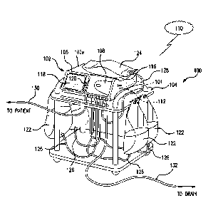
[0025] FIG. 1 shows an example of a dialysis system 100 (e.g., a peritoneal
dialysis (PD)
system) that is configured in accordance with an exemplary embodiment of the
system described
herein. In some implementations, the dialysis system 100 may be configured for
use at a
patient's home (e.g., a home PD system). The dialysis system 100 may include a
dialysis
machine 102 (e.g., a peritoneal dialysis machine 102, also referred to as a PD
cycler) and in
some embodiments the machine may be seated on a cart 104. The dialysis machine
102 may
include a housing 106, a door 108, and a cartridge interface for contacting a
disposable cassette,
or cartridge, where the cartridge is located within a compartment formed
between the cartridge
interface and the closed door 108. A heater tray 116 may be positioned on top
of the housing
106. The heater tray 116 may be any size and shape to accommodate a bag of
dialysate (e.g., a
5L bag of dialysate) for batch heating. The dialysis machine 102 may also
include a user
interface such as a touch screen 118 and control panel 120 operable by a user
(e.g., a caregiver or
a patient) to allow, for example, set up, initiation, and/or termination of a
dialysis treatment.
[0026] Dialysate bags 122 may be suspended from hooks the sides of the cart
104, and a heater
bag 124 may be positioned in the heater tray 116. Hanging the dialysate bags
122 may improve
6
CA 03069753 2020-01-10
WO 2019/060603 PCT/US2018/052036
air management as air content may be disposed by gravity to a top portion of
the dialysate bag
122. Although four dialysate bags 122 are illustrated in FIG. 1, any number of
dialysate bags
may be connectable to the dialysis machine 102 (e.g., 1 to 5 bags, or more),
and reference made
to first and second bags is not limiting to the total number of bags used in a
dialysis system 100.
For example, the dialysis machine may have dialysate bags 122a, . .. 122n
connectable in the
system 101. In some embodiments, connectors and tubing ports may connect the
dialysate bags
122 and lines for transferring dialysate. Dialysate from the dialysate bags
122 may be
transferred to the heater bag 124 in batches. For example, a batch of
dialysate may be
transferred from the dialysate bags 122 to the heater bag 124, where the
dialysate is heated by
the heating element. When the batch of dialysate has reached a predetermined
temperature (e.g.,
approximately 98 -100 F, 37 C), the batch of dialys ate may be flowed into the
patient. The
dialysate bags 122 and the heater bag 124 may be connected to the cartridge
via dialysate bag
lines or tubing 126 and a heater bag line or tubing 128, respectively. The
dialysate bag lines 126
may be used to pass dialysate from dialysate bags 122 to the cartridge during
use, and the heater
bag line 128 may be used to pass dialysate back and forth between the
cartridge and the heater
bag 124 during use. In addition, a patient line 130 and a drain line 132 may
be connected to the
cartridge. The patient line 130 may be connected to a patient's abdomen via a
catheter and may
be used to pass dialysate back and forth between the cartridge and the
patient's peritoneal cavity
during use. The drain line 132 may be connected to a drain or drain receptacle
and may be used
to pass dialysate from the cartridge to the drain or drain receptacle during
use (see FIGS. 4A-
4B).
[0027] The touch screen 118 and the control panel 120 may allow an operator to
input various
treatment parameters to the dialysis machine 102 and to otherwise control the
dialysis machine
102. In addition, the touch screen 118 may serve as a display. The touch
screen 118 may
function to provide information to the patient and the operator of the
dialysis system 100. For
example, the touch screen 118 may display information related to a dialysis
treatment to be
applied to the patient, including information related to a prescription.
[0028] The dialysis machine 102 may include a processing module 101 that
resides inside the
dialysis machine 102, the processing module 101 being configured to
communicate with the
touch screen 118 and the control panel 120. The processing module 101 may be
configured to
receive data from the touch screen 118 the control panel 120 and sensors,
e.g., weight, air, flow,
temperature, and/or pressure sensors, and control the dialysis machine 102
based on the received
data. For example, the processing module 101 may adjust the operating
parameters of the
dialysis machine 102.
7
CA 03069753 2020-01-10
WO 2019/060603 PCT/US2018/052036
[0029] The dialysis machine 102 may be configured to connect to a network 110.
The
connection to network 110 may be via a wired and/or wireless connection. The
dialysis machine
102 may include a connection component 112 configured to facilitate the
connection to the
network 110. The connection component 112 may be a transceiver for wireless
connections
and/or other signal processor for processing signals transmitted and received
over a wired
connection. Other medical devices (e.g., other dialysis machines) or
components may be
configured to connect to the network 110 and communicate with the dialysis
machine 102.
[0030] Referring now to FIG. 2, another exemplary embodiment of a dialysis
machine 200 in
accordance with the present disclosure is shown. The dialysis machine 200 may
be implemented
in the peritoneal dialysis system 100 and may be in lieu of the dialysis
machine 102, and may
include, for example, a housing 206, a processing module 201, a connection
component 212, a
touch screen 218, and a control panel 220 operable by a user (e.g., a
caregiver or a patient) to
allow, for example, set up, initiation, and/or termination of a dialysis
treatment. The processing
module 201 and the connection component 212 may be configured similarly to the
processing
module 101 and connection component 112 described above. However, instead of a
heater tray
for a heater bag and batch heating being positioned on a top surface 102a of
the housing as
shown in FIG. 1, one or more heating elements may be disposed internal to the
dialysis machine
200. For example, a warmer pouch 224 may be insertable into an opening 210 in
a direction
indicated at arrow 214. It is also understood that the warmer pouch 224 may be
connectable to
the dialysis machine 200 via tubing, or fluid lines, via a cartridge. The
tubing may be
connectable so that dialysate may flow from the dialysate bags 122, through
the warmer pouch
224 for heating, and to the patient.
[0031] In such in-line heating embodiments, the warmer pouch 224 may be
configured so
dialysate may continually flow through the warmer pouch (instead of
transferred in batches for
batch heating) to achieve a predetermined temperature before flowing into the
patient. For
example, in some embodiments the dialysate may continually flow through the
warmer pouch
224 at a rate between approximately 100-300 mL/min. Internal heating elements
(not shown)
may be positioned above and/or below the opening 210, so that when the warmer
pouch 224 is
inserted into the opening 210, the one or more heating elements may affect the
temperature of
dialysate flowing through the warmer pouch 224. In some embodiments, the
internal warmer
pouch may instead be a portion of tubing in the system that is passed by,
around, or otherwise
configured with respect to, a heating element(s).
[0032] In some embodiments, a dialysis machine 102, 200 may provide an active
measurement
of the dialysate temperature in dialysate bags, heater bag, and/or the warmer
pouch e.g., in the
CA 03069753 2020-01-10
WO 2019/060603 PCT/US2018/052036
dialysate bags 122, the heater bag 124, and/or the warmer pouch 224, or
combinations thereof of
FIGS. 1-2. It is understood that FIG. 1 illustrates that dialysate may be
transferable to and
stored in the heater bag 124 by "batch" until reaching an acceptable
temperature for use, and that
FIG. 2 illustrates dialysate continuously flowing through the warmer pouch 224
"in-line" with
the dialysis machine 200, reaching an acceptable temperature by the
application of internal
heating elements.
[0033] As described above, embodiments having an in-line warmer pouch 224 may
be more
susceptible than embodiments utilizing batch heating to temperature variation
of the dialysate.
For example, if flow rate changes during treatment, such as a kink in the
tubing occurring or an
obstruction on the inlet, dialysate may dwell in the warmer pouch 224 for a
longer time period
and reach a higher than intended temperature. If dialysate is higher than
approximately 41 C, or
105 F-106T, it may not be delivered to the patient to ensure patient safety.
[0034] Referring to FIG. 3, a schematic of an exemplary embodiment of a
dialysis machine 300
and a controller 305 in accordance with the present disclosure are shown. The
dialysis machine
300 may be a home dialysis machine, e.g., a peritoneal dialysis machine, for
performing a
dialysis treatment on a patient, and may be included in the system 100 for
dialysis machines 102,
200, described above with respect to FIGS. 1-2 and dialysis machine 102, 200.
Additionally,
components described with respect to the dialysis machine 300 may also be
included in the
dialysis machines 102, 200. A power source 325 may provide power and/or a
connection to an
external power source to the dialysis machine 102, 200, 300, 405, 455.
[0035] The controller 305 may automatically control execution of a treatment
function during a
course of dialysis treatment. For example, the controller 305 may control the
delivery and
transfer of dialysate as shown in FIGS. 4A-4B and FIG. 5 for dialysis machines
102, 200, 300,
405, 455. The controller 305 may be operatively connected to sensors 340 and
deliver one or
more signals to execute one or more treatment functions, or a course of
treatment associated with
various treatment systems. For example, dialysis treatment may include
transferring dialysate
from the dialysate bag 122 to the heater bag 124 and then to the patient, or
delivering dialysate
from the dialysate bag 122 through the warmer pouch 224 to the patient), or a
course of
treatment associated with various treatment systems. In some embodiments, a
timer 355 may be
included for timing triggering of sensors 340. It is understood that sensors,
including but not
limited to pressure sensors, weight sensors, flow sensors, air sensors, and
temperature sensors,
may detect dialysate temperature, fluid volume, air content, fluid flow rate,
and fluid flow
pressure for the dialysis machine 102, 200, 300, 405, 455 to determine flow
delivery to and from
the patient. For example, the dialysis machine 102, 200, 300, 405, 455 may
include a plurality of
sensors for detection and/or measurement of any combination of temperature,
pressure, volume,
9
CA 03069753 2020-01-10
WO 2019/060603 PCT/US2018/052036
air content, fluid flow. Multiple sensors may also be included to detect
and/or measure
individually the temperature, pressure, volume, air content, fluid flow.
[0036] In some embodiments, the controller 305, processor 310, and/or memory
320 of the
dialysis machine 300 may receive sensor 340 signals indicating complete
dialysate transfer of the
dialysate bags, and indicating process parameters, such as temperature,
pressure, air content,
volume, flow rate, and the like. When either temperature and/or air content of
the dialysate is at
an unacceptable level, the controller 305, processor 310, and/or memory 320
may divert the
temporarily unusable dialysate into a temporary holding container (e.g., an
alternative dialysate
bag) to be delivered to the patient later in the treatment. For example, each
dialysate bag (e.g.,
the dialysate bags 122 and the heater bag 124) may contain an approximate
amount of dialysate,
such that "approximate amount" may be defined as a 3L dialysate bag containing
3000 to 3150
mL, a .5L dialysate bag containing 5000 to 5250 mL, and a 6L dialysate bag
containing 6000 to
6300 mL. Although bag volume is described herein as 3L, 5L and 6L, it is
understood that the
specified volumes are only exemplary and bag volume may be any volume, and an
"approximate" volume may be in a range within 10% of the desired volume. The
controller 305
may also detect connection of all dialysate bags 122 connected. The controller
305 may monitor
the dialysate bags 122 for dialysate transfer, so that the controller 305
knows the volume of
dialysate that has been transferred from each dialysate bag 122, and if
dialysate has been
diverted to a dialysate bag 122 as a temporary holding container.
[0037] Communication between the controller 305 and the treatment system may
be bi-
directional, whereby the treatment system acknowledges control signals, and/or
may provide
state information associated with the treatment system and/or requested
operations. For
example, system state information may include a state associated with specific
operations to be
executed by the treatment system (e.g., trigger pump to deliver dialysate,
trigger pumps and/or
compressors to deliver filtered blood, and the like) and a status associated
with specific
operations (e.g., ready to execute, executing, completed, successfully
completed, queued for
execution, waiting for control signal, and the like).
[0038] In embodiments, the dialysis machine 102, 200, 300 may include at least
one pump 350
operatively connected to the controller 305. During a treatment operation, the
controller 305
may control the pump 350 for pumping fluid, e.g., fresh and spent dialysate,
to and from a
patient. The pump 350 may also pump dialysate from the dialysate bag 122 to
the heater bag
124, or to another dialysate bag 122. In embodiments where the warmer pouch
224 is in-line
with the dialysis machine 200, the pump 350 may pump the dialysate through the
warmer pouch
224 directly to the patient. The controller 305 may also be operatively
connected to a speaker
330 and a microphone 335 disposed in the dialysis machine 300. A user input
interface 315 may
CA 03069753 2020-01-10
WO 2019/060603 PCT/US2018/052036
include a combination of hardware and software components that allow the
controller 305 to
communicate with an external entity, such as a patient or other user, and a
display 302 may
display information to the user or medical professional. These components may
be configured to
receive information from actions such as physical movement or gestures and
verbal intonation.
For example, the patient may enter via the user input interface 315 sizes of
the dialysate bags
122 for use in treatment. In embodiments, the components of the user input
interface 315 may
provide information to external entities. Examples of the components that may
be employed
within the user input interface 315 include keypads, buttons, microphones,
touch screens, gesture
recognition devices, display screens, and speakers. The dialysis machine 102,
200, 300 may also
be wirelessly connectable via the antenna 345 for remote communication.
[0039] As shown in FIG. 3, sensors 340 may be included for monitoring one or
more parameters
and may be operatively connected to at least the controller 305, processor
310, and memory 320.
The processor 310 may be configured to execute an operating system, which may
provide
platform services to application software, e.g., for operating the dialysis
machine 300. These
platform services may include inter-process and network communication, file
system
management and standard database manipulation. One or more of many operating
systems may
be used, and examples are not limited to any particular operating system or
operating system
characteristic. In some examples, the processor 310 may be configured to
execute a real-time
operating system (RTOS), such as RTLinux, or a non-real time operating system,
such as BSD
or GNU/Linux.
[0040] According to a variety of examples, the processor 310 may be a
commercially available
processor such as a processor manufactured by INTEL, AMD, MOTOROLA, and
FREESCALE.
However, the processor 310 may be any type of processor, multiprocessor or
controller, whether
commercially available or specially manufactured. For instance, according to
one example, the
processor 310 may include an MPC823 microprocessor manufactured by MOTOROLA.
[0041] The memory 320 may include a computer readable and writeable
nonvolatile data storage
medium configured to store non-transitory instructions and data. In addition,
the memory 320
may include a processor memory that stores data during operation of the
processor 310. In some
examples, the processor memory includes a relatively high performance,
volatile, random access
memory such as dynamic random access memory (DRAM), static memory (SRAM), or
synchronous DRAM. However, the processor memory may include any device for
storing data,
such as a non-volatile memory, with sufficient throughput and storage capacity
to support the
functions described herein. Further, examples are not limited to a particular
memory, memory
system, or data storage system.
11
CA 03069753 2020-01-10
WO 2019/060603 PCT/US2018/052036
[0042] The instructions stored on the memory 320 may include executable
programs or other
code that may be executed by the processor 310. The instructions may be
persistently stored as
encoded signals, and the instructions may cause the processor 310 to perform
the functions
described herein. The memory 320 may include information that is recorded, on
or in, the
medium, and this information may be processed by the processor 310 during
execution of
instructions. The memory 320 may also include, for example, specification of
data records for
user timing requirements, timing for treatment and/or operations, and historic
sensor
information. The medium may, for example, be optical disk, magnetic disk or
flash memory,
among others, and may be permanently affixed to, or removable from, the
controller 305.
[0043] A pressure sensor may be included for monitoring fluid pressure of the
dialysis machine
102, 200, 300, although the sensors 340 may also include any of a heart rate
sensor, a respiration
sensor, a temperature sensor, a flow sensor, a weight sensor, a video sensor,
an air sensor, an air
bubble sensor, a thermal imaging sensor, an electroencephalogram sensor, a
motion sensor,
audio sensor, an accelerometer, or capacitance sensor. In some embodiments, a
flow sensor may
detect and/or measure a flow of dialysate, e.g., to measure the dialysate
transferred from the first
and second bags to the patient. In some embodiments, a flow sensor may also
detect and/or
measure a flow of dialysate through the warmer pouch 224, or to the heater bag
124. It is
appreciated that the sensors 340 may include sensors with varying sampling
rates, including
wireless sensors.
[0044] The controller 305 may be disposed in the dialysis machine 102, 200,
300 or may be
coupled to the dialysis machine 102, 200, 300 via a communication port or
wireless
communication links, shown schematically as communication element 306 (see
FIG. 3).
According to various examples, the communication element 306 may support a
variety of one or
more standards and protocols, examples of which include USB, WiFi, TCP/IP,
Ethernet,
Bluetooth, Zigbee, CAN-bus, IP, IPV6, UDP, UTN, HTTP, HTTPS, P, SNMP, CDMA,
NMEA and/or GSM. As a component disposed within the dialysis machine 300, the
controller
305 may be operatively connected to any one or more of the sensors 340, pump
350, or
combinations thereof. The controller 305 may communicate control signals or
triggering
voltages to the components of the dialysis machine 102, 200, 300. As
discussed, exemplary
embodiments of the controller 305 may include wireless communication
interfaces. The
controller 305 may detect remote devices to determine if any remote sensors
are available to
augment any sensor data being used to evaluate the patient.
[0045] Referring now to FIGS. 4A, 4B, and FIG. 5, an exemplary embodiment of a
method for
minimizing dialysate waste in accordance with the present disclosure is shown.
FIG. 4A
illustrates a dialysis system 400 including a dialysis machine 405 similar to
the dialysis machine
12
CA 03069753 2020-01-10
WO 2019/060603 PCT/US2018/052036
102 in FIG. 1, including a heater bag 124 disposed on a heating element on a
top of the dialysis
machine 405. FIG. 4B illustrates a dialysis system 450 including a dialysis
machine 455 similar
to the dialysis machine 200 in FIG. 2, where the warmer pouch 224 is in-line
with the dialysis
machine 455. FIG. 5 shows an exemplary embodiment of a flow diagram of a
method 500 for
operating a dialysis machine, with a treatment beginning at step 505.
[0046] During treatment, a volume of dialysate may enter the patient's abdomen
and remain for
a period of time, e.g., a dwell time. During the dwell time, the dialysate may
cause flow across
the peritoneum of contaminants/toxins and/or particulates from a patient's
blood and exchange
substances and fluids (e.g., electrolytes, urea, glucose, albumin, osmotically
active particles, and
other small molecules). At the end of the dwell time, the used dialysate,
ultrafiltrate, and/or
contaminants/toxins may be flowed out of the patient's abdomen and purged to a
drain 410
connected to the tubing 420, e.g., the drain line 132, indicated by arrow 440
and illustrated in
dash-lines. This exchange of fresh dialysate and used dialysate after a dwell
time may occur for
several cycles depending on the patient's treatment regimen.
[0047] Both embodiments illustrated in FIGS. 4A and 4B may include dialysate
containers 425,
which in some embodiments may be dialysate bags 122 (see FIG. 1), where
dialysate transfer
between the respective dialysis machine and the dialysate bags 122 may be
similar. In some
embodiments, the dialys ate container 425 may be an additional holding
reservoir. The additional
holding reservoir may be any type of a container, e.g., a bag, or other
configuration for retaining
dialysate, and/or for receiving diverted dialysate for later use in the
treatment. In some
embodiments, an additional holding reservoir may be configured in a similar
manner to the
dialysate bags 122. The additional holding reservoir, separate from the
dialysate bags, may
prevent mixing diverted dialysate with undelivered dialysate, although a
separate additional
holding reservoir may be optional. In some embodiments, separate additional
holding reservoir
may be advantageous to isolate detected air from dialysate. For example,
diverting back into a
dialysate bag 122 may reintroduce air for detection later in the treatment.
Three dialysate
containers 425 are shown merely for illustrative purposes, and it is
understood that a treatment
regimen may need more or less dialysate bags 122, and other dialysate
containers may be
connected to the dialysis machine 405, 455. It is understood that the
individual patient treatment
regimen and total dialysate volume in each bag may dictate how many dialysate
bags 122 and/or
other dialysate containers are connected to the dialysis machine 405, 455. For
example,
dialysate bags 122 may contain the same volume of dialysate, or a different
volume of dialysate.
Dialysate bags 122 may be sized to contain approximately 3L, 5L, and/or 6L of
dialysate. If a
patient treatment regimen calls for 9L total of dialysate, a patient may
connect a 6L dialysate bag
13
CA 03069753 2020-01-10
WO 2019/060603 PCT/US2018/052036
and a 3L dialysate bag to the dialysis machine 102. A dialysis treatment may
include
approximately 3L-30L of dialysate and may connect up to five bags to deliver
the prescribed
treatment.
[0048] At step 510, a volume of dialysate may be delivered to a patient. For
example, dialysate
may be delivered into the patient after being heated to a predetermined
temperature via tubing
420. In batch heating embodiments, the dialysate may flow into the patient
after heating to a
predetermined temperature in the heater bag 124. In in-line heating
embodiments, the dialysate
may flow directly from dialysate bags to the patient by continuously flowing
through the warmer
pouch. The warmer pouch 224 may have a pathway for the dialysate to flow
through, e.g., a
tortuous or circuitous flow path, so that the dialysate may reach the
predetermined temperature
by the time the dialysate exits the flow path to continue into the patient.
The dialysate may be
heated up from room temperature to body temperature (approximately 98 F -100
F, 37 C) by
batch or in-line heating, as described above. In some embodiments, tubing 420
may be fluid
lines connecting a patient to the dialysis system via a cartridge, including
hut not limited to a
dialysate bag lines 126, a heater bag line 128, a patient line 130, and a
drain line 132.
Additionally, it is also understood that for each treatment procedure, the
patient receives a
sterilized and disposable "set," including but not limited to tubing, a
cartridge, dialysate bags,
and the like. After each treatment, each "set" may be disposed of to minimize
any potential
contamination.
[0049] In embodiments, a volume of dialysate may be transferrable by batch to
the heater bag
124 via the tubing 420 for heating before flowing into the patient, as shown
in FIG. 4A and
indicated by arrow 430. In other embodiments, a volume of dialysate may be
transferrable
through the warmer pouch 224 in-line with the dialysis machine 200 for heating
before flowing
into the patient, as shown in FIG. 4B and indicated by arrow 460. When the
heater bag 124 is
disposed above the dialysis machine 405 as illustrated in FIG. 4A, a batch of
dialysate may flow
from the heater bag 124 to the machine 405 indicated by arrow 435, e.g., to
the cartridge for
pumping into the patient. In other embodiments, as illustrated in FIG. 4B,
when the warmer
pouch 224 is in-line with the dialysis machine 455, extra steps may not be
needed to flow the
dialysate to the machine 455.
[0050] In some embodiments, e.g., illustrated in FIG. 4A, the dialysis machine
102, 405 may
transfer an amount equal to a fill volume or a volume of the heater bag 124,
plus an additional
predetermined amount (e.g., 300 mL) in order to ensure sufficient dialysate
volume for the next
fill. However, air content may still be present in the heater bag 124. For
example, the heater bag
124 may lie flat on the top surface 102a of the dialysis machine 102, 300,
405, 455 such that an
14
CA 03069753 2020-01-10
WO 2019/060603 PCT/US2018/052036
air content contained in the heater bag 124 may migrate toward a side of the
bag, possibly near a
connection point 415 of the tubing 420. Some embodiments may account for this
by tilting the
top surface 102a, skewing the heater bag 124 to having a tubing connector at
the lowest side to
minimize air content (as air may flow up to an upper portion of the heater bag
124). However,
this may not account for user set-up variability, e.g., home use possibly
utilizing uneven
surfaces. An alert or alarm, or multiple alerts or alarms, may be triggered by
a detected air
content even though a sufficient amount of dialysate is present.
[0051] At step 515, the dialysis machine 102, 200, 300, 405, 455 may determine
whether a
temperature of the dialysate is acceptable for delivery to the patient. In
embodiments, a sensor
340 (e.g., a temperature sensor) may detect the dialysate temperature, and the
processor 310 may
compare the detected dialysate temperature to a predetermined maximum
temperature. For
example, the predetermined maximum temperature may be approximately 41 C. At
step 520, the
dialysis machine 102, 200, 300, 405, 455 may determine whether an air content
(e.g., volume of
air) is detected in the dialysate, and compare the detected air content to a
predetermined
maximum air content. In embodiments, another sensor 340 may detect air
bubbles, a fluid
pressure, or other value to determine if an unacceptable level of air is
present. Unacceptable
levels of air content may affect patient comfort during or after treatment.
[0052] If the dialysate temperature is acceptable at step 515, and/or an
acceptable volume of air
is detected in the dialysate at step 520, the dialysis machine 102, 200, 300,
405, 455 may
determine if another condition has been detected that may necessitate
dialysate diversion at step
530. This other condition may include detecting a new treatment set of a
cartridge and tubing,
priming the tubing, or detecting a treatment event alarm or flow stop, or
combinations thereof. It
is understood that the other condition may be an individual condition,
multiples of an individual
condition, or a combination of the conditions. In some embodiments, when a new
treatment set
of disposable bags, lines, cartridge, and the like, is introduced in the
dialysis machine 102, 200,
300, 405, 455, the set may need to be primed, e.g., dialysate is flowed
through to remove initial
air content, to verify valves and connections, and the like. This may be a
condition that
generates an automatic signal when the new set is connected, for the dialysis
machine to prime
the set, or a user may manually initiate priming upon completion of set-up. In
some
embodiments, an event may occur during treatment, including but not limited to
a kink in the
tubing 420, a leak is detected, a contamination is detected, or combinations
thereof, which may
deviate from treatment protocol. It is understood that these events may be
individual, or in
combination with each other, or multiples of each event. In some embodiments,
the treatment
flow into the patient may be paused or stopped, and an alarm may signal to the
user and/or a
CA 03069753 2020-01-10
WO 2019/060603 PCT/US2018/052036
remote source, although dialysate may still be flowing through the set of
tubing and the
cartridge, and may still be heating. If no other condition is detected, then
dialysate may be
flowed into the patient at step 535. If another condition is detected, a
condition signal may be
generated and in response to the condition signal, the dialysate, a dialysate
volume may be
diverted as described below with respect to step 525.
[0053] It should be understood that steps 515, 520, and 530 may be performed
in any order, or
simultaneously, and may not be dependent on the outcome of the other. In
embodiments, the
dialysis machine 102, 200, 300, 405, 455 may perform only step 515 or multiple
steps 515, only
step 520 or multiple steps 520, only step 530 or multiple steps 530, or a
combination of step 515,
520, and 530 or a combination of multiple steps 515, 520, and 530.
[0054] If a comparison of the detected dialysate temperature is above a
predetermined
temperature (e.g., approximately 41 C) at step 515, a comparison of the air
volume (e.g., air
content) detected at step 520 is above a predetermined maximum air content,
and/or another
condition is detected to generate a signal (e.g., priming the set, a treatment
event occurs), then
the temporarily unusable dialysate volume may be diverted at step 525. In some
embodiments,
the volume of dialysate may be transferred to a dialysate container. For
example, a dialysate
container 425 may be dialysate bags 122, which may be unused dialysate bags
from which
dialysate has not yet been transferred or a used dialysate bag, or both, from
which the dialys ate
has been transferred, where diverted dialysate is held in a dialysate bag 122
not currently being
used by the dialysis machine 102, 200, 300, 405, 455. The dialysate container
425 may be an
additional holding reservoir, separate from the dialysate bags 122 and
configured for receiving
diverted dialysate. The dialysate container 425 may act as a holding reservoir
for diverted
dialysate and allow the temporarily unusable dialysate to later be used in the
treatment. For
example, overheated dialysate may have time to cool (or may be actively
cooled) to a
temperature acceptable for delivering to the patient. Additionally, air
bubbles may be allowed to
converge and flow to an upper portion of the dialysate bag so that air content
delivered may be
minimized. The dialysis machine 102, 200, 300, 405, 455 may later be able to
transfer the now-
usable dialysate from the dialysate container 425 to the patient.
[0055] In some embodiments, the dialysate may passively cool to an acceptable
temperature in
the dial ysate container 425, e.g., room temperature, through the course of
treatment, although in
other embodiments, the dialysis system may include an active cooling mechanism
for the
overheated dialysate. For example, the dialysate container 425 may be disposed
adjacent to or
coupled with an active cooling mechanism to actively lower the temperature of
the diverted
16
CA 03069753 2020-01-10
WO 2019/060603 PCT/US2018/052036
dialysate. The active cooling mechanism may include any one or a combination
of a heat
exchanger, a cooling element, a fan, a thermoelectric cooler (TEC), or the
like.
[0056] In some embodiments, if the dialysate volume is diverted only for
exceeding a
predetermined temperature, the diverted dialysate may be flowed through an
active cooling
mechanism to lower the temperature of the dialysate, and then flowed to the
patient. Instead of
storing the diverted dialysate in a separate container, the dialysis system
may continue to flow
the diverted dialysate in parallel with dialysate flowing to the patient
(e.g., via tubing 420) to the
active cooling mechanism. Once the diverted dialysate is an acceptable
temperature, the diverted
dialysate may then be rejoined with dialysate flowing to the patient.
[0057] In embodiments, when dialysate is diverted from a first dialysate bag,
the diverted
dialysate may be transferred any other dialysate bag in which dialysate is not
being immediately
drawn or from which all dialysate has already been drawn, or which is
specially designated as a
holdover reservoir for diverted dialysate volumes. For example, FIG. 4A
illustrates arrow 445
diverting dialysate into the farthest (from the dialysis machine 405)
dialysate container 425 while
dialysate is being drawn from the nearest (to the dialysis machine 405)
dialysate container 425.
Similarly, FIG. 4B illustrates arrow 465 diverting dialysate into the farthest
(from the dialysis
machine 455) dialysate container 425 while dialysate is being drawn from the
nearest (to the
dialysis machine 455) dialysate container 425.
[0058] In embodiments, the dialysis machine 102, 200, 300, 405, 455 may be
configured to
monitor which dialysate container 425 is flowing dialysate, and determine the
dialysate container
425 to divert temporarily unusable dialysate. The diverted dialysate may be
diverted to a single
dialysate container 425, or a combination of multiple dialysate containers
425. In some
embodiments, the dialys ate container 425 to receive the diverted dialys ate
may be initially empty
of dialysate, although in some embodiments, a volume of dialysate may be
present. It may not
be disadvantageous to mix, as fresh dialysate and diverted dialysate may be of
the same
concentrations. For example, in batch heating embodiments, dialysate from
different dialysate
containers 425 may be flowed into the heater bag 124, where it mixes together
before flowing
into the patient.
[0059] If the dialysate temperature is acceptable at step 515, no air content
or an acceptable
volume of air is detected in the dialysate at step 520, and/or no other
condition is detected at step
530, the treatment may continue at step 535, exchanging fresh dialysate and
used dialysate after
a dwell time for a number of cycles dependent on the patient's treatment
regimen. Dialysate
may be transferred from all of the dialysate containers 425 (e.g., dialysate
bags 122, heater bag
124, and/or warmer pouch 224, and dialysate container) connected to the
dialysis machine 102,
17
85910334
200, 300, 405, 455 to complete a treatment. For example, in embodiments, the
dialysis machine
102, 200, 300, 405, 455 may determine if the diverted dialysate volume is
acceptable for use at
step 540. A temperature sensor 340 may detect the temperature of the diverted
dialysate, and a
sensor 340 (e.g., a pressure sensor and/or weight sensor) may determine the
air content present in
the diverted dialysate volume. Other sensors 340, or a combination of
temperature, pressure,
weight, flow, and other sensors 340 may also be used in the dialysis machine
102, 200, 300, 405,
455 for detecting and monitoring the dialysate. If the diverted dialysate is
acceptable for use, the
dialysate volume may be delivered to the patient as in step 510. If the
diverted dialysate volume
is not acceptable for transfer to the patient, e.g., the dialysate temperature
still exceeds
approximately 41 C, an air content exceeds a predetermined maximum air
content, then at step
555 the dialysis machine 102, 200, 300, 405, 455 may continue to hold the
diverted dialysate
volume and deliver dialysate from other non-diverted sources, e.g., dialysate
bags 122. In
embodiments, the dialysis machine 102, 200, 300, 405, 455 may include a timer
355 or other
timing function to periodically check the diverted dialys ate volume for
acceptability. The timer
355 may be a predetermined time period, e.g., the diverted dialysate may be
monitored in 5 or 10
minute intervals. In some embodiments, the diverted dialysate volume may be
checked prior to
diverting additional dialysate.
[0060] By diverting the temporarily unusable dialysate (e.g., overheated,
containing air content
or excess air content, initial dialysate flow for priming) to a dialysate
container 425, it may be
usable later in the treatment, thereby minimizing wasted dialysate. The
dialysis machine 102,
200, 300, 405, 455 may determine at step 545 whether an entire dialysate
treatment has been
delivered to the patient. For example, the dialysis machine 102, 200, 300,
405, 455 may monitor
levels of dialysate in all of the dialysate containers 425 throughout the
treatment. For example,
dialysate bags 122 may be completely transferred, either to the patient, or
diverted to a dialysate
container 425. As mentioned, multiple dialysate bags may be connectable to the
dialysis
machine 102, 200, 300, 405, 455 for delivering a prescribed treatment to a
patient. Each
dialysate bag may be transferred to the patient as described in co-pending
Application Serial No.
15/711,111, filed September 21, 2017, entitled "Automatic Dialysate Detection
in Dialysis
Machines" to Plahey et al.
[0061] If dialysate is diverted back into one of the dialysate bags 122, the
dialysis machine 102,
200, 300, 405, 455 may ensure that the diverted dialysate may be delivered to
the patient before
the treatment ends at step 550, thereby ensuring the patient receives a more
complete prescribed
treatment. In embodiments where an additional holding reservoir is included,
the dialysis
machine 102, 200, 300, 405, 455 may first transfer dialysate from all of the
dialysate bags 122.
18
Date Recue/Date Received 2021-07-05
CA 03069753 2020-01-10
WO 2019/060603 PCT/US2018/052036
As described above, at step 540, if temporarily unusable dialysate was
diverted to the additional
holding reservoir, the dialysis machine 102, 200, 300, 405, 455 may determine
if the temperature
and air content are at acceptable levels so that the diverted dialysate may
then be delivered to the
patient.
[0062] Referring now to FIG. 6, another exemplary embodiment of a system and
method of
delivering dialysate is shown. It is understood that steps 605, 610, 615, 620,
630, 635, 645, and
650 are identical to steps 505, 510, 515, 520, 530, 535, 545, and 550,
respectively, as described
above. In the flow diagram 600 of FIG. 6, instead of flowing the diverted
dialysate as it is
determined to be acceptable (e.g., decreases to an acceptable temperature),
the diverted dialysate
may be used after all the dialysate from dialysate bags 122 has been delivered
to the patient.
[0063] As described above, if the dialysate temperature is above a
predetermined temperature,
e.g., 41 C at step 615, if air is detected in the dialysate at step 620, or
another condition has been
detected at step 630, the volume of dialysate may be diverted at step 625. As
mentioned, the
dialysate may be diverted to an additional holding reservoir, or an unused
dialysate bag, or a
used dialysate bag, or combinations thereof. For example, the dialysis machine
102, 200, 300,
405, 455 may determine where to divert the dialysate based on the treatment
cycle. When the
dialysate has been diverted, the process may continue by returning to step
610, delivering
another volume of dialysate to the patient, e.g., another cycle.
[0064] At step 645, the dialysis machine 102, 200, 300, 405, 455 may determine
if the entire
dialysate treatment has been delivered to the patient. If the total treatment
volume has not been
delivered to the patient, at step 655, the dialysis machine 102, 200, 300,
405, 455 may determine
if the diverted dialysate is acceptable to flow into the patient, e.g., the
diverted dialysate may be
at an acceptable temperature for use. Air content may also converge to reduce
air bubbles so less
air may be delivered to the patient. If the dialysate is acceptable for the
patient, the dialysis
machine may continue by delivering the diverted dialysate at step 610. If the
diverted dialysate
is not acceptable for the patient to receive, the dialysis machine 102, 200,
300, 405, 455 may
alarm. If a treatment volume delivered to the patient is less than a
predetermined percentage of
the total treatment volume, the dialysis machine 102, 200, 300, 405, 455 may
alarm and may
shut down without delivering any additional dialysate. For example, if the
treatment volume
delivered is less than 90% of the total treatment volume, the dialysis machine
102, 200, 300, 405,
455 may alarm or alert a user or medical professional that the treatment may
be ineffective. In
some embodiments, if a treatment volume delivered to the patient is less than
a predetermined
percentage of the total treatment volume, but greater than a minimum
percentage of the total
treatment volume, the dialysis machine may complete treatment hut also
generate an alarm or
19
CA 03069753 2020-01-10
WO 2019/060603 PCT/US2018/052036
alert to notify the user or medical professional of the total treatment. For
example, if the
treatment volume delivered is greater than 90% of the total treatment volume,
but less than
100%, the dialysis machine 102, 200, 300, 405, 455 may complete the treatment
but also alert or
alarm to notify the user or medical professional. Although the patient may
receive an effective
level of treatment, the alarm may alert the user to a condition of the
dialysis machine 102, 200,
300, 405, 455 to address before beginning another treatment.
[0065] If at step 645 the dialysis machine 102, 200, 300, 405, 455 determines
that the entire
dialysate treatment has been delivered to the patient, the treatment may end
at step 650.
[0066] Some embodiments of the disclosed system may be implemented, for
example, using
a storage medium, a computer-readable medium or an article of manufacture
which may store an
instruction or a set of instructions that, if executed by a machine (i.e.,
processor or
microcontroller), may cause the machine to perform a method and/or operations
in accordance
with embodiments of the disclosure. In addition, a server or database server
may include
machine readable media configured to store machine executable program
instructions. Such a
machine may include, for example, any suitable processing platform, computing
platform,
computing device, processing device, computing system, processing system,
computer,
processor, or the like, and may be implemented using any suitable combination
of hardware,
software, firmware, or combinations thereof and utilized in systems,
subsystems, components, or
sub-components thereof. The computer-readable medium or article may include,
for example,
any suitable type of memory unit, memory device, memory article, memory
medium, storage
device, storage article, storage medium and/or storage unit, for example,
memory (including
non-transitory memory), removable or non-removable media, erasable or non-
erasable media,
writeable or re-writeable media, digital or analog media, hard disk, floppy
disk, Compact Disk
Read Only Memory (CD-ROM), Compact Disk Recordable (CD-R), Compact Disk
Rewriteable
(CD-RW), optical disk, magnetic media, magneto-optical media, removable memory
cards or
disks, various types of Digital Versatile Disk (DVD), a tape, a cassette, or
the like. The
instructions may include any suitable type of code, such as source code,
compiled code,
interpreted code, executable code, static code, dynamic code, encrypted code,
and the like,
implemented using any suitable high-level, low-level, object-oriented, visual,
compiled and/or
interpreted programming language.
[0067] As used herein, an element or operation recited in the singular and
proceeded with the
word "a" or "an" should be understood as not excluding plural elements or
operations, unless
such exclusion is explicitly recited. Furthermore, references to "one
embodiment" of the present
CA 03069753 2020-01-10
WO 2019/060603 PCT/US2018/052036
disclosure are not intended to be interpreted as excluding the existence of
additional
embodiments that also incorporate the recited features.
[0068] The present disclosure is not to be limited in scope by the specific
embodiments
described herein. Indeed, other various embodiments of and modifications to
the present
disclosure, in addition to those described herein, will be apparent to those
of ordinary skill in the
art from the foregoing description and accompanying drawings. Thus, such other
embodiments
and modifications are intended to fall within the scope of the present
disclosure. Furthermore,
although the present disclosure has been described herein in the context of a
particular
implementation in a particular environment for a particular purpose, those of
ordinary skill in the
art will recognize that its usefulness is not limited thereto and that the
present disclosure may be
beneficially implemented in any number of environments for any number of
purposes.
Accordingly, the claims set forth below should be construed in view of the
full breadth and spirit
of the present disclosure as described herein.
21