Note: Descriptions are shown in the official language in which they were submitted.
CA 03069845 2020-01-13
WO 2018/231463 PCT/US2018/034094
-1-
SYSTEMS AND METHODS FOR HARVESTING PLANTS
CROSS REFERENCE TO RELATED APPLICATIONS
[0001] This application claims the benefit of U.S. Utility Patent
Application No.
15/985,885, filed May 22, 2018, U.S. Provisional Patent Application Numbers
62/519,661
and 62/519,304 all filed on June 14, 2017, the entire contents of which are
herein
incorporated by reference.
TECHNICAL FIELD
[0002] Embodiments described herein generally relate to systems and
methods for
harvesting plants in a grow pod and, more specifically, to harvesting plants
in a grow pod
based on a weight, a chlorophyll level, and/or a height of the plant.
BACKGROUND
[0003] While crop growth technologies have advanced over the years, there
are
still many problems in the farming and crop industry today. As an example,
while
technological advances have increased efficiency and production of various
crops, many
factors may affect a harvest, such as weather, disease, infestation, and the
like.
Additionally, while the United States currently has suitable farmland to
adequately
provide food for the U.S. population, other countries and future populations
may not have
enough farmland to provide the appropriate amount of food.
[0004] Harvesting plants requires a great deal of human labor and time.
Additionally, once plants are harvested, the land where the plants had been
grown needs
some time until planting new plants. Thus, a system for automatically
harvesting plants in
an indoor crop grow pod in a continuous manner may be needed.
SUMMARY
[0005] In one embodiment, a harvesting system is provided. The harvesting
system includes a track, a cart configured to move along the track, the cart
including an
upper plate configured to support a plant, one or more sensors, a lifter, and
a controller.
CA 03069845 2020-01-13
WO 2018/231463 PCT/US2018/034094
-2-
The controller includes one or more processors, one or more memory modules,
and
machine readable instructions stored in the one or more memory modules that,
when
executed by the one or more processors, cause the controller to: receive
information from
the one or more sensors, determine whether the plant in the cart is ready to
harvest based
on the information, and send to the lifter an instruction for tilting the
upper plate by a
degree in response to determination that the plant in the cart is ready to
harvest.
[0006] In another embodiment, a harvesting system includes a track, a
cart
configured to move along the track, one or more sensors and a controller. The
cart
includes a lower plate, an upper plate configured to support a plant and
pivotally coupled
to the lower plate, and an actuator configured to rotate the upper plate
against the lower
plate. The controller includes one or more processors, one or more memory
modules, and
machine readable instructions stored in the one or more memory modules that,
when
executed by the one or more processors, cause the controller to: receive
information from
the one or more sensors, determine whether the plant in the cart is ready to
harvest based
on the information, and send to the actuator an instruction for rotating the
upper plate by a
degree against the lower plate in response to determination that the plant in
the cart is
ready to harvest.
[0007] In another embodiment, a method for harvesting a plant in a cart
is
provided. The method includes sending, to the cart, an instruction for moving
on a track,
receiving information about the plant in the cart from one or more sensors,
determining
whether the plant in the cart is ready to harvest based on the information,
and sending, to a
lifter, an instruction to tilt an upper plate of the cart by a degree against
a lower plate of
the cart in response to determination that the plant in the cart is ready to
harvest.
[0008] These and additional features provided by the embodiments
described
herein will be more fully understood in view of the following detailed
description, in
conjunction with the drawings.
BRIEF DESCRIPTION OF THE DRAWINGS
[0009] The embodiments set forth in the drawings are illustrative and
exemplary in
nature and not intended to limit the disclosure. The following detailed
description of the
CA 03069845 2020-01-13
WO 2018/231463 PCT/US2018/034094
-3-
illustrative embodiments can be understood when read in conjunction with the
following
drawings, where like structure is indicated with like reference numerals and
in which:
[0010] FIG. 1 depicts an assembly line grow pod, according to embodiments
described herein;
[0011] FIG. 2 depicts an industrial cart, according to embodiments
described
herein;
[0012] FIG. 3A depicts an industrial cart in a normal mode, according to
embodiments described herein;
[0013] FIG. 3B depicts an industrial cart in a harvest mode, according to
embodiments described herein;
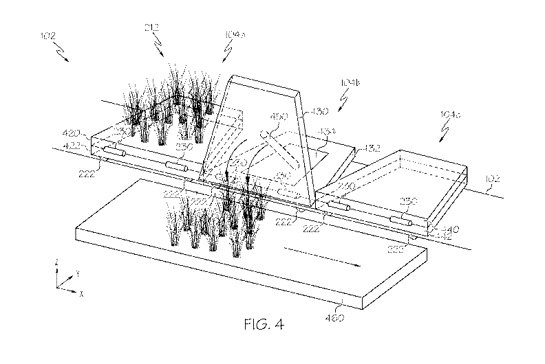
[0014] FIG. 4 depicts harvesting plant on an industrial cart, according
to
embodiments described herein;
[0015] FIG. 5A depicts an industrial cart in a normal mode, according to
embodiments described herein;
[0016] FIG. 5B depicts an industrial cart in a harvest mode, according to
embodiments described herein;
[0017] FIG. 5C depicts an industrial cart in a harvest mode, according to
embodiments described herein;
[0018] FIG. 5D depicts an industrial cart in a normal mode, according to
embodiments described herein;
[0019] FIG. 5E depicts an industrial cart in a harvest mode, according to
embodiments described herein;
[0020] FIG. 6 depict a harvesting system, according to embodiments
described
herein;
[0021] FIG. 7 depicts an interface of a user computing device, according
to
embodiments described herein;
CA 03069845 2020-01-13
WO 2018/231463 PCT/US2018/034094
-4-
[0022] FIG. 8 depicts a flowchart for harvesting plants in a grow pod
using weight
sensors, according to embodiments described herein; and
[0023] FIG. 9 depicts a computing device for an assembly line grow pod,
according to embodiments described herein.
DETAILED DESCRIPTION
[0024] Embodiments disclosed herein include harvesting systems. The
harvesting
system includes a track, a cart configured to move along the track, the cart
including an
upper plate configured to support a plant, one or more sensors, a lifter, and
a controller.
The controller includes one or more processors, one or more memory modules,
and
machine readable instructions stored in the one or more memory modules that,
when
executed by the one or more processors, cause the controller to: receive
information from
the one or more sensors, determine whether the plant in the cart is ready to
harvest based
on the information, and send to the lifter an instruction for tilting the
upper plate by a
degree in response to determination that the plant in the cart is ready to
harvest. The
harvesting system according to the present disclosure provides automatic
harvesting
system for carts moving a track. According to the present disclosure, because
the plant is
hydroponically cultivated and the roots of the plant are intertwined, the
harvesting process
may be implemented fast and efficiently.
[0025] Referring now to the drawings, FIG. 1 depicts an assembly line
grow pod
100 that receives a plurality of industrial carts 104, according to
embodiments described
herein. The assembly line grow pod 100 may be positioned on an x-y plane as
shown in
FIG. 1. As illustrated, the assembly line grow pod 100 may include a track 102
that holds
one or more industrial carts 104. Each of the one or more industrial carts
104, as
described in more detail with reference to FIG. 2, may include one or more
wheels 222a,
222b, 222c, and 222d rotatably coupled to the industrial cart 104 and
supported on the
track 102, as described in more detail with reference to FIG. 2.
[0026] Additionally, a drive motor is coupled to the industrial cart 104.
In some
embodiments, the drive motor may be coupled to at least one of the one or more
wheels
222a, 222b, 222c, and 222d such that the industrial cart 104 may be propelled
along the
track 102 in response to a signal transmitted to the drive motor. In other
embodiments, the
CA 03069845 2020-01-13
WO 2018/231463 PCT/US2018/034094
-5-
drive motor may be rotatably coupled to the track 102. For example, the drive
motor may
be rotatably coupled to the track 102 through one or more gears which engage a
plurality
of teeth arranged along the track 102 such that the industrial cart 104 may be
propelled
along the track 102.
[0027] The track 102 may include a plurality of modular track sections.
The
plurality of modular track sections may include a plurality of straight
modular track
sections and a plurality of curved modular track sections. The track 102 may
include an
ascending portion 102a, a descending portion 102b, and a connection portion
102c. The
ascending portion 102a and the descending portion 102b may include the
plurality of
curved modular track sections. The ascending portion 102a may wrap around
(e.g., in a
counterclockwise direction as depicted in FIG. 1) a first axis such that the
industrial carts
104 ascend upward in a vertical direction. The first axis may be parallel to
the z axis as
shown in FIG. 1 (i.e., perpendicular to the x-y plane).
[0028] The descending portion 102b may be wrapped around a second axis
(e.g.,
in a counterclockwise direction as depicted in FIG. 1) that is substantially
parallel to the
first axis, such that the industrial carts 104 may be returned closer to
ground level. The
plurality of curved modular track sections of the descending portion 102b may
be tilted
relative to the x-y plane (i.e., the ground) by a predetermined angle.
[0029] The connection portion 102c may include a plurality of straight
modular
track sections. The connection portion 102c may be relatively level with
respect to the x-y
plane (although this is not a requirement) and is utilized to transfer the
industrial carts 104
from the ascending portion 102a to the descending portion 102b. In some
embodiments, a
second connection portion (not shown in FIG. 1) may be positioned near ground
level that
couples the descending portion 102b to the ascending portion 102a such that
the industrial
carts 104 may be transferred from the descending portion 102b to the ascending
portion
102a. The second connection portion may include a plurality of straight
modular track
sections.
[0030] In some embodiments, the track 102 may include two or more
parallel rails
that support the industrial cart 104 via the one or more wheels 222a, 222b,
222c, and 222d
rotatably coupled thereto. In some embodiments, at least two of the parallel
rails of the
track 102 are electrically conductive, thus capable of transmitting
communication signals
CA 03069845 2020-01-13
WO 2018/231463 PCT/US2018/034094
-6-
and/or power to and from the industrial cart 104. In some embodiments, a
portion of the
track 102 is electrically conductive and a portion of the one or more wheels
222a, 222b,
222c, and 222d are in electrical contact with the portion of the track 102
which is
electrically conductive. In some embodiments, the track 102 may be segmented
into more
than one electrical circuit. That is, the electrically conductive portion of
the track 102 may
be segmented with a non-conductive section such that a first electrically
conductive
portion of the track 102 is electrically isolated from a second electrically
conductive
portion of the track 102 which is adjacent to the first electrically
conductive portion of the
track 102.
[0031] The communication signals and power may further be received and/or
transmitted via the one or more wheels 222a, 222b, 222c, and 222d of the
industrial cart
104 and to and from various components of industrial cart 104, as described in
more detail
herein. Various components of the industrial cart 104, as described in more
detail herein,
may include the drive motor, the control device, and one or more sensors.
[0032] In some embodiments, the communication signals and power signals
may
include an encoded address specific to an industrial cart 104 and each
industrial cart 104
may include a unique address such that multiple communication signals and
power may be
transmitted over the same track 102 and received and/or executed by their
intended
recipient. For example, the assembly line grow pod 100 system may implement a
digital
command control system (DCC). DDC systems encode a digital packet having a
command and an address of an intended recipient, for example, in the form of a
pulse
width modulated signal that is transmitted along with power to the track 102.
[0033] In such a system, each industrial cart 104 includes a decoder,
which may be
the control device coupled to the industrial cart 104, designated with a
unique address.
When the decoder receives a digital packet corresponding to its unique
address, the
decoder executes the embedded command. In some embodiments, the industrial
cart 104
may also include an encoder, which may be the control device coupled to the
industrial
cart 104, for generating and transmitting communications signals from the
industrial cart
104, thereby enabling the industrial cart 104 to communicate with other
industrial carts
104 positioned along the track 102 and/or other systems or computing devices
communicatively coupled with the track 102.
CA 03069845 2020-01-13
WO 2018/231463 PCT/US2018/034094
-7-
[0034] While the implementation of a DCC system is disclosed herein as an
example of providing communication signals along with power to a designated
recipient
along a common interface (e.g., the track 102) any system and method capable
of
transmitting communication signals along with power to and from a specified
recipient
may be implemented. In some embodiments, digital data may be transmitted over
AC
circuits by utilizing a zero-cross, step, and/or other communication protocol.
[0035] While not explicitly illustrated in FIG. 1, the assembly line grow
pod 100
may also include a harvesting component, a tray washing component, and other
systems
and components coupled to and/or in-line with the track 102. In some
embodiments, the
assembly line grow pod 100 may include a plurality of lighting devices, such
as light
emitting diodes (LEDs). The lighting devices may be disposed on the track 102
opposite
the industrial carts 104, such that the lighting devices direct light waves to
the industrial
carts 104 on the portion the track 102 directly below. In some embodiments,
the lighting
devices are configured to create a plurality of different colors and/or
wavelengths of light,
depending on the application, the type of plant being grown, and/or other
factors. Each of
the plurality of lighting devices may include a unique address such that a
master controller
106 may communicate with each of the plurality of lighting devices. While in
some
embodiments, LEDs are utilized for this purpose, this is not a requirement.
Any lighting
device that produces low heat and provides the desired functionality may be
utilized.
[0036] Also depicted in FIG. 1 is a master controller 106. The master
controller
106 may include a computing device 130, a nutrient dosing component, a water
distribution component, and/or other hardware for controlling various
components of the
assembly line grow pod 100. In some embodiments, the master controller 106
and/or the
computing device 130 are communicatively coupled to a network 620 (as depicted
and
further described with reference to FIG. 6).
[0037] Coupled to the master controller 106 is a seeder component 108.
The
seeder component 108 may be configured to seed one or more industrial carts
104 as the
industrial carts 104 pass the seeder in the assembly line. Depending on the
particular
embodiment, each industrial cart 104 may include a single section tray for
receiving a
plurality of seeds. Some embodiments may include a multiple section tray for
receiving
individual seeds in each section (or cell). In the embodiments with a single
section tray,
the seeder component 108 may detect presence of the respective industrial cart
104 and
CA 03069845 2020-01-13
WO 2018/231463 PCT/US2018/034094
-8-
may begin laying seed across an area of the single section tray. The seed may
be laid out
according to a desired depth of seed, a desired number of seeds, a desired
surface area of
seeds, and/or according to other criteria. In some embodiments, the seeds may
be pre-
treated with nutrients and/or anti-buoyancy agents (such as water) as these
embodiments
may not utilize soil to grow the seeds and thus might need to be submerged.
[0038] In the embodiments where a multiple section tray is utilized with
one or
more of the industrial carts 104, the seeder component 108 may be configured
to
individually insert seeds into one or more of the sections of the tray. Again,
the seeds may
be distributed on the tray (or into individual cells) according to a desired
number of seeds,
a desired area the seeds should cover, a desired depth of seeds, etc. In some
embodiments,
the seeder component 108 may communicate the identification of the seeds being
distributed to the master controller 106.
[0039] The watering component may be coupled to one or more water lines
110,
which distribute water and/or nutrients to one or more trays at predetermined
areas of the
assembly line grow pod 100. In some embodiments, seeds may be sprayed to
reduce
buoyancy and then flooded. Additionally, water usage and consumption may be
monitored, such that at subsequent watering stations, this data may be
utilized to
determine an amount of water to apply to a seed at that time.
[0040] Also depicted in FIG. 1 are airflow lines 112. Specifically, the
master
controller 106 may include and/or be coupled to one or more components that
delivers
airflow for temperature control, humidity control, pressure control, carbon
dioxide control,
oxygen control, nitrogen control, etc. Accordingly, the airflow lines 112 may
distribute
the airflow at predetermined areas in the assembly line grow pod 100. For
example, the
airflow lines 112 may extend to each story of the ascending portion 102a and
the
descending portion 102b.
[0041] It should be understood that while some embodiments of the track
may be
configured for use with a grow pod, such as that depicted in FIG. 1, this is
merely an
example. The track and track communications are not so limited and can be
utilized for
any track system where communication is desired.
CA 03069845 2020-01-13
WO 2018/231463 PCT/US2018/034094
-9-
[0042] FIG. 2 depicts an industrial cart 104 that may be utilized for the
assembly
line grow pod 100, according to embodiments described herein. As illustrated,
the
industrial cart 104 includes a tray section 220 and one or more wheels 222a,
222b, 222c,
and 222d. The tray section 220 includes an upper plate 220a and a lower plate
220b. The
one or more wheels 222a, 222b, 222c, and 222d may be configured to rotatably
couple
with the track 102, as well as receive power, from the track 102. The track
102 may
additionally be configured to facilitate communication with the industrial
cart 104 through
the one or more wheels 222a, 222b, 222c, and 222d.
[0043] In some embodiments, one or more components may be coupled to the
tray
section 220. For example, a drive motor 226, a cart computing device 228,
and/or a
payload 212 may be coupled to the tray section 220 of the industrial cart 104.
The tray
section 220 may additionally include a payload 212. Depending on the
particular
embodiment, the payload 212 may be configured as plants (such as in an
assembly line
grow pod 100); however this is not a requirement, as any payload 212 may be
utilized.
[0044] The drive motor 226 may be configured as an electric motor and/or
any
device capable of propelling the industrial cart 104 along the track 102. For
example, the
drive motor 226 may be configured as a stepper motor, an alternating current
(AC) or
direct current (DC) brushless motor, a DC brushed motor, or the like. In some
embodiments, the drive motor 226 may comprise electronic circuitry which may
adjust the
operation of the drive motor 226 in response to a communication signal (e.g.,
a command
or control signal) transmitted to and received by the drive motor 226. The
drive motor 226
may be coupled to the tray section 220 of the industrial cart 104 or directly
coupled to the
industrial cart 104.
[0045] In some embodiments, the cart computing device 228 may control the
drive
motor 226 in response to a leading sensor 232, a trailing sensor 234, and/or
an orthogonal
sensor 236 included on the industrial cart 104. Each of the leading sensor
232, the trailing
sensor 234, and the orthogonal sensor 236 may comprise an infrared sensor,
visual light
sensor, an ultrasonic sensor, a pressure sensor, a proximity sensor, a motion
sensor, a
contact sensor, an image sensor, an inductive sensor (e.g., a magnetometer) or
other type
of sensor. The cart 104 further comprises a weight sensor 242 configured to
measure the
payload 212 on the cart 104.
CA 03069845 2020-01-13
WO 2018/231463 PCT/US2018/034094
-10-
[0046] In some embodiments, the leading sensor 232, the trailing sensor
234, the
orthogonal sensor 236 and/or the weight sensor 242 may be communicatively
coupled to
the master controller 106 (FIG. 1). In some embodiments, the leading sensor
232, the
trailing sensor 234, the orthogonal sensor 236 and/or the weight sensor 242
may generate
one or more signals that may be transmitted via the one or more wheels 222a,
222b, 222c,
and 222d and the track 102 (FIG. 1). Similarly, some embodiments may be
configured
with the track 102 and/or the industrial cart 104 communicatively coupled to a
network
620 (FIG. 6). Therefore, the one or more signals may be transmitted to the
master
controller 106 via the network 550 over network interface hardware 934 (FIG.
9) or the
track 102 and in response, the master controller 106 may return a control
signal to the
drive motor 226 for controlling the operation of one or more drive motors 226
of one or
more industrial carts 104 positioned on the track 102.
[0047] In some embodiments, location markers 224 may be placed along the
track
102 or the supporting structures to the track 102 at pre-defined intervals.
The orthogonal
sensor 236, for example, comprises a photo-eye type sensor and may be coupled
to the
industrial cart 104 such that the photo-eye type sensor may view the location
markers 224
positioned along the track 102 below the industrial cart 104. As such, the
cart computing
device 228 and/or master controller 106 may receive one or more signals
generated from
the photo-eye in response to detecting a location marker 224 as the industrial
cart travels
along the track 102. The cart computing device 228 and/or master controller
106, from the
one or more signals, may determine the speed of the industrial cart 104. The
speed
information may be transmitted to the master controller 106 via the network
620 over
network interface hardware 634 (FIG. 9).
[0048] FIGS. 3A and 3B depict an operation of the tray of the industrial
cart 104
that may be utilized for the assembly line grow pod 100, according to
embodiments
described herein. The industrial cart 104 includes an upper plate 220a, a
lower plate 220b,
and one or more wheels 222 as shown in FIG. 2. The upper plate 220a is
pivotally
coupled to the lower plate 220b via one or more hinges 230. FIG. 3A depicts
the
industrial cart 104 in a normal mode moving on the track 102. FIG. 3B depicts
the
industrial cart 104 in a harvesting mode. During the harvesting mode, the
upper plate
CA 03069845 2020-01-13
WO 2018/231463 PCT/US2018/034094
-11-
220a is pivotally rotated against the lower plate 220b such that payload on
the upper plate
220a may be dumped out from the cart 104. As depicted in FIG. 3B, the lower
plate 220b
includes an opening 240 that allows a lifter 450 (FIG. 4) to move through.
[0049] FIG. 4 depicts harvesting operation of industrial carts, according
to
embodiments shown and described herein. As illustrated, industrial carts 104a,
104b, and
104c are disposed on a track 102. Each of the industrial carts 104a, 104b, and
104c is
depicted as being similarly configured as the industrial cart 104 from FIG. 2.
As discussed
above, at least a portion of the one or more wheels 222 (or other portion of
the industrial
carts 104a, 104b, and 104c) may couple with the track 102 to receive
communication
signals and/or power.
[0050] The industrial carts 104a, 104b, and 104c may move along the track
102 in
+x direction. That is, the industrial cart 104a will be at the position of the
industrial cart
104b shown in FIG. 4 at a certain point of time. In embodiments, the
industrial cart 104a
operates in a normal mode carrying payload 212, and the industrial cart 104b
is in a
harvesting mode. The industrial cart 104b may operate in a harvest mode when
the
industrial cart 104b is determined to be in a harvesting area. For example,
the industrial
cart 104b may receive a signal from the master controller 106 that the
industrial cart 104b
is in a harvesting area. In response to receiving the signal indicating that
the industrial cart
104b is in the harvesting area, the industrial cart 104b may stop moving in +x
direction.
As another example, the track 102 may include a harvesting location marker.
The
industrial cart 104b may read the harvesting location marker using a photo-eye
detector,
and stop moving in response to reading the harvesting location marker.
[0051] A lifter 450 located at the bottom of the industrial cart 104b
pushes the
upper plate 430 of the industrial cart 104b through an opening 434 in +z
direction. The
detailed operations of the lifter 450 will be described below with reference
to FIGS. 5A
through 5C. In response, the upper plate 430 is rotated about the hinges 230
and payload
on the industrial cart 104b is dumped out from the industrial cart 104b as
indicated by
arrows in FIG. 4. The payload on the industrial cart 104b may be dumped to a
conveyor
belt 460 which transmit the payload to a collecting area. Once the payload is
dumped out
from the industrial cart 104b, the lifter 450 moves down in ¨z direction such
that the upper
plate 430 is placed on the lower plate 422 similar to the industrial cart
104c.
CA 03069845 2020-01-13
WO 2018/231463 PCT/US2018/034094
-12-
[0052] In some embodiments, before the upper plate 430 is pushed up by
the lifter
450, the water in the industrial cart 104b may be removed. For example, the
industrial cart
104b may include water detection sensors for detecting water in the industrial
cart 104b.
The master controller 106 may determine that there is water in the industrial
cart 104b,
and send an instruction for removing water from the industrial cart 104b. For
example, the
master controller 106 may send an instruction to the lifter 450 to rotate such
that the
industrial cart 104b is slightly tilted (e.g., by 5 degrees). Then, the water
in the industrial
cart 104b may gather at the edge of the industrial cart 104b where there is a
hole through
which the water flows out from the industrial cart 104b. As another example,
the master
controller 106 may send an instruction to a vacuum robot to remove water from
the
industrial cart 104b.
[0053] FIGS. 5A, 5B, and 5C depict a y-z plane view of the industrial
carts shown
in FIG. 4, according to one or more embodiments shown and described herein.
FIG. 5A
depicts a y-z plane view of the industrial cart 104a depicted in FIG. 4. In
embodiments,
the upper plate 220a is placed on and parallel to the lower plate 220b. The
upper plate
220a is coupled to the lower plate 220b via one or more hinges 230. Wheels 222
of the
industrial cart 104a are on the track 102 such that the industrial cart 104a
moves along the
track 102.
[0054] FIG. 5B depicts a y-z plane view of the industrial cart 104b
depicted in
FIG. 4. The industrial cart 104b is in a harvesting mode. The industrial cart
104 stops
moving on the track 102. The lifter 450 is configured to rotate about a pivot
454. As
shown in FIG. 5B, the original position of the lifter 450 is indicated in
broken lines. In
embodiments, the lifter 450 may receive an instruction from the master
controller 106 to
rotate about the pivot 454. In some embodiments, the lifter 450 may receive an
instruction
from the industrial cart 104b to rotate about the pivot 454. In response to
receiving the
instruction, the lifter 450 rotates counterclockwise to push up the upper
plate 430.
[0055] Similarly, the upper plate 430 rotates counterclockwise around the
hinge
230 as the lifter 450 pushes the upper plate 430. The payload 212 on the upper
plate 430
is dumped out from the upper plate 430 into the conveyor belt 460. While the
lifter 450 in
FIG. 5B rotates to push upward the upper plate 430, any other operation may be
implement to push upward the upper plate 430. For example, the lifter 450 may
move +z
direction to push the upper plate 430 upward. In embodiments, the payload 212
is
CA 03069845 2020-01-13
WO 2018/231463 PCT/US2018/034094
-13-
hydroponically cultivated and the roots of the payload 212 are intertwined. As
such, the
entire of the payload 212 may be dumped out of the upper plate 430 at a time.
In addition,
because the payload 212 had been grown on the cart 104b without any dirt, the
harvesting
process may be simplified by skipping the process of cleaning out dirt. The
lifter 450
includes a wheel 452 rotatably coupled to the lifter 450 such that the wheel
452 smoothly
pushes the upper plate 430 by rotating when the lifter 450 is in contact with
the upper plate
430 and pushes the upper plate 430.
[0056] In embodiments, the lifter 450 pushes the upper plate 430 upward
until the
upper plate 430 rotates by a certain angel (e.g., 60 degrees). The angle may
be
predetermined such that payload on the upper plate 430 may slide down or be
dumped out
from the upper plate 430. In some embodiments, the hinge 230 may prevent the
upper
plate 430 from rotating more than a certain degrees (e.g., 80 degrees).
[0057] FIG. 5C depicts a y-z plane view of the industrial cart 104b
depicted in
FIG. 4. After the payload 212 is dumped out from the upper plate 430, the
lifter 450 is
operated to rotate about the pivot 454 clockwise as depicted in FIG. 5C. The
upper plate
430 of the industrial cart 104b rotates clockwise as the lifter 450 moves in
¨z direction.
Once the upper plate 430 is placed upon and parallel to the lower plate 432,
the industrial
cart 104b resumes moving on the track 102. In some embodiments, the industrial
cart
104b determines whether the payload 212 was dumped out from the upper plate
430
before resuming moving on the track 102. For example, a weight sensor in the
upper plate
430 may measure weight of an object on the upper plate 430. If the measured
weight is
above a threshold value, the industrial cart 104b may transmit an instruction
to the lifter
450 to rotate counterclockwise again in order to dump remaining payload on the
upper
plate 430.
[0058] FIGS. 5D and 5E depict harvesting plants according another
embodiment
shown and described herein. As illustrated, the industrial cart 504 is
disposed on a track
102. The industrial cart 504 is depicted as being similarly configured as the
industrial cart
104 from FIG. 2. The industrial cart 504 includes an upper plate 520 and a
lower plate
522. The upper plate 520 is coupled to the lower plate 522 via an actuator
530. The
actuator 530 may include an electric motor configured to rotate the upper
plate 520 against
the lower plate 522. For example, as shown in FIG. 5E, the actuator 530
rotates the upper
plate 520 counterclockwise such that the payload 120 is dumped out from the
upper plate
CA 03069845 2020-01-13
WO 2018/231463 PCT/US2018/034094
-14-
520 into the conveyor belt 460. The actuator 530 may rotate the upper plate
520 by a
predetermined degree. Once the payload 120 is dumped, the actuator 530 may
rotate the
upper plate 520 clockwise until the upper plate 520 is placed upon and
parallel to the
lower plate 522.
[0059] FIG. 6 depicts harvesting plants in carts, according to
embodiments
described herein. Industrial carts 104a, 104b, and 104c move along the track
102 in +x
direction through wheels as discussed above with reference to FIG. 4. The
industrial cart
104a includes an upper plate 420 and a lower plate 422. The industrial cart
104b includes
an upper plate 430 and a lower plate 432. The industrial cart 104c includes an
upper plate
440 and a lower plate 442. While the track 102 is illustrated as a straight
track in FIG. 6,
the track 102 may be a curved track constituting the ascending portion 102a or
the
descending portion 102b.
[0060] In embodiments, the carts 104a, 104b, and 104c include weight
sensors
610a, 610b, and 610c, respectively. Each of the weight sensors 610a, 610b, and
610c may
be placed in the upper plates 420, 430, and 440 of the carts 104a, 104b, and
104c,
respectively. The weight sensors 610a, 610b, and 610c are configured to
measure the
weight of a payload on the carts, such as plants. The carts 104a, 104b, and
104c also
include cart computing devices 612a, 612b, and 612c, respectively. The cart
computing
devices 612a, 612b, and 612c may be communicatively coupled to the weight
sensors
610a, 610b, and 610c and receive weight information from the weight sensors
610a, 610b,
and 610c. The cart computing devices 612a, 612b, and 612c may have wireless
network
interface for communicating with the master controller 106 through a network
620. The
master controller 106 may determine whether the measured weight is greater
than a
threshold weight. The threshold value may be determined based on a plant.
[0061] If it is determined that the measured weight is greater than the
threshold
weight, the master controller 106 may send an instruction to the lifter 450 to
rotate as
depicted in FIG. 5B to raise the upper plate to dump out payload on the
industrial cart, or
send an instruction to the actuator 530 in FIG. 5D to rotate the upper plate
520. In some
embodiments, each of the carts 104a, 104b, and 104c may include a plurality of
weight
sensors corresponding to a plurality of cells of the carts 104a, 104b, and
104c. The
plurality of weight sensors may determine weights of individual cells or
plants on the
carts.
CA 03069845 2020-01-13
WO 2018/231463 PCT/US2018/034094
-15-
[0062] In some embodiments, a plurality of weight sensors may be placed
on the
track 102. The weight sensors are configured to measure the weights of the
carts on the
track 102 and transmit the weights to the master controller 106. The master
controller 106
may determine the weight of payload on a cart by subtracting the weight of the
cart from
the weight received from the weight sensors on the track 102.
[0063] A proximity sensor 602 may be positioned over the carts 104a,
104b, and
104c. In embodiments, the proximity sensor 602 may be attached under the track
102 as
depicted in FIG. 6. The proximity sensor 602 may be configured to measure a
distance
between the proximity sensor 602 and the plants on industrial carts. For
example, the
proximity sensor 602 may transmit waves and receive waves reflected from the
plants.
Based on the travelling time of the waves, the proximity sensor 602 may
determine the
distance between the proximity sensor and the plants. In some embodiments, the
proximity sensor 602 may be configured to detect an object within a certain
distance. For
example, the proximity sensor 602 may detect the plants in the carts 104b if
the plants are
within 5 inches from the proximity sensor 602. In some embodiments, the
proximity
sensor 602 may include laser scanners, capacitive displacement sensors,
Doppler Effect
sensors, eddy-current sensors, ultrasonic sensors, magnetic sensors, optical
sensors, radar
sensors, sonar sensors, LIDAR sensors or the like. Some embodiments may not
include
the proximity sensor 602.
[0064] The proximity sensor 602 may have wireless network interface for
communicating with the master controller 106 through a network 620. In some
embodiments, the proximity sensor 602 may communicate with the master
controller 106
through wired connection. The master controller 106 may determine the height
of payload
on the industrial cart based on the measured distance. For example, the master
controller
106 calculates the height of payload by subtracting the measured distance from
a distance
between the proximity sensor 602 and the upper plate 430 of the industrial
cart 104b. The
master controller 106 may determine whether the calculated height is greater
than a
threshold height. The threshold height may be determined based on a plant. For
example,
plant logic 544b of the master controller 106 may store a name of plant and
corresponding
threshold height.
[0065] If it is determined that the calculated height is greater than the
threshold
height, the master controller 106 may send an instruction to the lifter 450 to
rotate as
CA 03069845 2020-01-13
WO 2018/231463 PCT/US2018/034094
-16-
depicted in FIG. 5B to raise the upper plate to dump out payload on the
industrial cart. In
some embodiments, a plurality of proximity sensors 602 may measure distances
between
the proximity sensors and the payload, and transmit the distances to the
master controller
106. The master controller 106 calculates an average height of the payload
based on the
received distances from the plurality of proximity sensors 602 and determines
whether the
average height is greater than the threshold height.
[0066] A camera 604 may be positioned over the carts 104a, 104b, and
104c. In
embodiments, the camera 604 may be attached under the track 102 as depicted in
FIG. 6.
The camera 604 may be configured to capture an image of the plants in the cart
104b. The
camera 604 may have a wider angle lens to capture plants of more than one
carts. For
example, the camera 604 may capture the images of payload in the carts 104a,
104b, and
104c. The camera 604 may include a special filter that filters out artificial
LED lights
from lighting devices in the assembly line grow pod 100 such that the camera
604 may
capture the natural colors of the plants.
[0067] The camera 604 may transmit the captured image of the payload to
the
master controller 106. The camera 604 may have wireless network interface for
communicating with the master controller 106 through a network 620. In some
embodiments, the camera 604 may communicate with the master controller 106
through
wired connection. The master controller 106 may determine whether payload is
ready to
harvest based on the color of the captured image. In embodiments, the master
controller
106 may compare the color of the captured image with a threshold color for the
identified
plant on the industrial cart. The predetermined color for one or more plants
may be stored
in the plant logic 544b of the master controller 106. For example, the master
controller
compares RGB levels of the captured image with the RGB levels of the
predetermined
color, and determines that the plant is ready to harvest based on the
comparison.
[0068] The master controller 106 may include a computing device 130. The
computing device 130 may include a memory component 540, which stores systems
logic
544a and plant logic 544b. As described in more detail below, the systems
logic 544a may
monitor and control operations of one or more of the components of the
assembly line
grow pod 100. For example, the systems logic 544a may monitor and control
operations
of the light devices, the water distribution component, the nutrient
distribution component,
the air distribution component, and harvesting components including the lifter
450. The
CA 03069845 2020-01-13
WO 2018/231463 PCT/US2018/034094
-17-
plant logic 544b may be configured to determine and/or receive a recipe for
plant growth
and may facilitate implementation of the recipe via the systems logic 544a.
[0069] Additionally, the master controller 106 is coupled to a network
620. The
network 620 may include the internet or other wide area network, a local
network, such as
a local area network, a near field network, such as Bluetooth or a near field
communication (NFC) network. The network 620 is also coupled to a user
computing
device 622 and/or a remote computing device 624. The user computing device 622
may
include a personal computer, laptop, mobile device, tablet, server, etc. and
may be utilized
as an interface with a user. As an example, the total weight of plant in each
of the
industrial carts along with the identification of the industrial cart may be
transmitted to the
user computing device 622. The average height of a plant in each of the
industrial carts
may be also transmitted to the user computing device 622. The display of the
user
computing device 622 may display the weight of plant for each of the carts, as
depicted in
FIG. 7.
[0070] FIG. 7 depicts a display 700 of the user computing device 622,
according to
one or more embodiments shown and described herein. In embodiments, the
display 700
may display three windows 710, 720, and 730 displaying information about the
industrial
carts 104a, 104b, and 104c depicted in FIG. 6 respectively. Each of the
windows 710,
720, and 730 displays information about plant carried in corresponding
industrial cart, the
weight of the plant, and the height of the plant. The display 700 may also
indicate the
industrial cart 104b is in a harvesting zone, and ask whether the plant in the
industrial cart
104b is ready to harvest. The harvesting zone may be a zone where the lifter
450 is
located, e.g., where the industrial cart 104b in FIG. 4 is located.
Additionally, the camera
604 may be positioned above the harvesting zone. In some embodiments, the
lighting
device above the harvesting zone may output natural light (e.g., daylight
toned light) such
that the camera 604 above the harvesting zone may capture the image of the
plant under
natural light. A user may initiate harvesting the plant by pushing the button
740. In
response to the push of the Yes button 740, the user computing device 622 may
send an
instruction to the lifter 450 to push up the upper plate 430 of the industrial
cart 104b such
that the plant on the industrial cart 104b is dumped out from the industrial
cart 104b. If
the user determines that the plant is not ready to harvest, the user may hold
off harvesting
the plant by pushing the No button 750.
CA 03069845 2020-01-13
WO 2018/231463 PCT/US2018/034094
-18-
[0071] Referring back to FIG. 6, similar to the user computing device
622, the
remote computing device 624 may include a server, personal computer, tablet,
mobile
device, etc. and may be utilized for machine to machine communications. The
remote
computing server 624 may store information about carts, identification
information about
plants on each of carts, weight of plants on each of the carts, height of
plants on each of
the carts, etc.
[0072] FIG. 8 depicts a flowchart for harvesting plants in a grow pod
using
sensors, according to one or more embodiments described herein. At block 810,
the
master controller 106 identifies plants on a cart. For example, the master
controller 106
may communicate with the carts 104a, 104b, and 104c and receive information
about the
plants in the carts 104a, 104b, and 104c. As another example, the information
about the
plants in the carts 104a, 104b, and 104c may be pre-stored in the master
controller 106
when the seeder component 108 seeds plant A in the carts 104a, 104b, and 104c.
[0073] Specifically, each of the carts may be assigned to a unique
address, and
when the seeder component 108 seeds a certain plant into a cart, the unique
address of the
cart is associated with the information about the certain plant. The
association of the
unique address and the information about the certain plant may be pre-stored
in the master
controller 106. For example, the master controller 106 may determine that
plant A is in
the industrial carts 104a, 104b, and 104c based on the association of the
unique addresses
for the carts 104a, 104b, and 104c and the information about plant A. As
another
example, an operator inputs the type of seeds that need to be grown in the
carts through
the user computing device 622, and the master controller 106 receives the type
of seeds
from the user computing device 622.
[0074] At block 820, the master controller 106 receives data from sensors
with
respect to corresponding industrial cart. In embodiments, the master
controller 106
receives the weight of the plants in the cart 104b from the weight sensor 610b
that
measures the weight of the plants on the cart 104b in FIG. 6. The master
controller 106
may calculate the actual weight of plant by subtracting the weight of water in
corresponding cart from the weight received from the weight sensor. In some
embodiments, the industrial cart may include sensors for detecting water that
has not been
absorbed by the plant and detecting an amount of the water. The master
controller 106
may estimate the weight of the water in the industrial cart based on data from
the sensors
CA 03069845 2020-01-13
WO 2018/231463 PCT/US2018/034094
-19-
for detecting water. In some embodiments, the water in the industrial cart may
be
removed prior to weighting as discussed above with reference to FIG. 4, and
thus, the
weight sensor 610b may accurately measure the weight of the plants in the cart
104b.
[0075] In some embodiments, the master controller 106 may also receive
data
from the proximity sensor 602. For example, the proximity sensor 602
determines the
distance between the proximity sensor 602 and the plants in the cart 104b in a
z-axis
direction, and transmits the distance data to the master controller 106
through the network
620. In some embodiments, the master controller 106 may receive a captured
image of the
plants on the industrial cart 104b from the camera 604. The camera 604 may
capture the
image of the plants in the industrial cart 104b. The camera 604 may include a
special
filter that filters out artificial LED lights from lighting devices in the
assembly line grow
pod 100 such that the captured image illustrates the natural colors of the
plants.
[0076] At block 830, the master controller 106 determines whether the
plant on the
industrial cart 104b is ready to harvest. In embodiments, the master
controller 106
determines whether the weight of plants on the cart is greater than a
threshold weight for
the identified plant. The threshold value may be a weight of a certain plant
in a cart that is
grown enough to be harvested. The threshold value may be stored in the plant
logic 544b,
and the master controller 106 may retrieve the threshold value from the plant
logic 544b.
[0077] For example, the plant logic 544b of the master controller 106 may
store a
name of plant and corresponding threshold weight, as shown in Table 1 below.
Plant Threshold weight
Plant A 10 kilograms
Plant B 3 kilograms
Plant C 5 kilograms
Plant D 2 kilograms
Table 1
[0078] The master controller 106 determines that the plant is ready to
harvest if the
weight of plant on the cart 104b is greater than the threshold weight. For
example, if the
weight of the plant A on the industrial cart 104b is 10.8 kilograms, the
master controller
106 determines that the plant is ready to harvest because the measured weight
is greater
CA 03069845 2020-01-13
WO 2018/231463 PCT/US2018/034094
-20-
than the threshold weight for plant A which is 10 kilograms.
[0079] In some embodiments, the master controller 106 determines the
average
height of the plants based on the data from the proximity sensor 602. If the
average height
of the plants is greater than a threshold height, the master controller 106
may determine
that the plant in the cart 104b is ready to harvest. For example, the plant
logic 544b of the
master controller 106 may store the name of plant and corresponding threshold
average
height, as shown in Table 2 below.
Plant Threshold height
Plant A 18 centimeters
Plant B 30 centimeters
Plant C 50 centimeters
Plant D 15 centimeters
Table 2
[0080] In some embodiments, the master controller 106 estimates the level
of
chlorophyll of the plant based on the captured image of the plant. For
example, the master
controller 106 may implement image processing on the captured image of the
plant to
estimate the level of chlorophyll of the plants. If the level of chlorophyll
for the plants in
the cart 104b is less than a predetermined value, the master controller 106
may determine
that the plant is ready to harvest.
[0081] At block 840, the master controller 106 transmits, to the lifter
450, an
instruction for tilting the upper plate 430 of the industrial cart 104b such
that plant on the
upper plate 430 of the industrial cart 104b is dumped out to from the
industrial cart 104b
in response to determination that the plant is ready to harvest. The lifter
450 pushes up the
upper plate 430 of the industrial cart 104b as shown in FIG. 5B in response to
receiving
the instruction from the master controller 106. In some embodiments, the
master
controller 106 transmits, to the actuator 530 (FIGS. 5A and 5B), an
instruction for tilting
the upper plate 430 of the industrial cart 104b such that plant on the upper
plate 430 of the
industrial cart 104b is dumped out to from the industrial cart 104b. In this
regard, the
assembly line grow pod 100 allow the plant on carts to be harvested at a
proper time (e.g.,
after the plants are fully grown or ripen).
CA 03069845 2020-01-13
WO 2018/231463 PCT/US2018/034094
-21-
[0082] FIG. 9
depicts a computing device 130 for an assembly line grow pod 100,
according to embodiments described herein. As illustrated, the computing
device 130
includes a processor 930, input/output hardware 932, the network interface
hardware 934,
a data storage component 936 (which stores systems data 938a, plant data 938b,
and/or
other data), and the memory component 540. The memory component 540 may be
configured as volatile and/or nonvolatile memory and as such, may include
random access
memory (including SRAM, DRAM, and/or other types of RAM), flash memory, secure
digital (SD) memory, registers, compact discs (CD), digital versatile discs
(DVD), and/or
other types of non-transitory computer-readable mediums. Depending on the
particular
embodiment, these non-transitory computer-readable mediums may reside within
the
computing device 130 and/or external to the computing device 130.
[0083] The
memory component 540 may store operating logic 942, the systems
logic 544a, and the plant logic 544b. The systems logic 544a and the plant
logic 544b may
each include a plurality of different pieces of logic, each of which may be
embodied as a
computer program, firmware, and/or hardware, as an example. A local interface
946 is
also included in FIG. 9 and may be implemented as a bus or other communication
interface to facilitate communication among the components of the computing
device 130.
[0084] The
processor 930 may include any processing component operable to
receive and execute instructions (such as from a data storage component 936
and/or the
memory component 540). The input/output hardware 932 may include and/or be
configured to interface with microphones, speakers, a display, and/or other
hardware.
[0085] The
network interface hardware 934 may include and/or be configured for
communicating with any wired or wireless networking hardware, including an
antenna, a
modem, LAN port, wireless fidelity (Wi-Fi) card, WiMax card, ZigBee card,
Bluetooth
chip, USB card, mobile communications hardware, and/or other hardware for
communicating with other networks and/or devices. From
this connection,
communication may be facilitated between the computing device 130 and other
computing
devices, such as the user computing device 622 and/or remote computing device
624.
[0086] The
operating logic 942 may include an operating system and/or other
software for managing components of the computing device 130. As also
discussed
above, systems logic 544a and the plant logic 544b may reside in the memory
component
CA 03069845 2020-01-13
WO 2018/231463 PCT/US2018/034094
-22-
540 and may be configured to perform the functionality, as described herein.
[0087] It should be understood that while the components in FIG. 9 are
illustrated
as residing within the computing device 130, this is merely an example. In
some
embodiments, one or more of the components may reside external to the
computing device
130. It should also be understood that, while the computing device 130 is
illustrated as a
single device, this is also merely an example. In some embodiments, the
systems logic
544a and the plant logic 544b may reside on different computing devices. As an
example,
one or more of the functionalities and/or components described herein may be
provided by
the user computing device 622 and/or remote computing device 624.
[0088] Additionally, while the computing device 130 is illustrated with
the
systems logic 544a and the plant logic 544b as separate logical components,
this is also an
example. In some embodiments, a single piece of logic (and/or or several
linked modules)
may cause the computing device 130 to provide the described functionality.
[0089] As illustrated above, various embodiments for harvesting plants in
a grow
pod are disclosed. These embodiments create a quick growing, small footprint,
chemical
free, low labor solution to growing microgreens and other plants for
harvesting. These
embodiments may create recipes and/or receive recipes that dictate the timing
and
wavelength of light, pressure, temperature, watering, nutrients, molecular
atmosphere,
and/or other variables the optimize plant growth and output. The recipe may be
implemented strictly and/or modified based on results of a particular plant,
tray, or crop.
[0090] Accordingly, some embodiments may include a harvesting system. The
harvesting system includes a track, a cart configured to move along the track,
the cart
including an upper plate configured to support a plant, one or more sensors, a
lifter, and a
controller. The controller includes one or more processors, one or more memory
modules,
and machine readable instructions stored in the one or more memory modules
that, when
executed by the one or more processors, cause the controller to: receive
information from
the one or more sensors, determine whether the plant in the cart is ready to
harvest based
on the information, and send to the lifter an instruction for tilting the
upper plate by a
degree in response to determination that the plant in the cart is ready to
harvest. The
claimed subject matter provides automatic harvesting system for carts moving a
track.
According to the claimed subject matter, because the plant is hydroponically
cultivated
CA 03069845 2020-01-13
WO 2018/231463 PCT/US2018/034094
-23-
and the roots of the payload 212 are intertwined, the harvesting process is
implemented
fast and efficiently.
[0091] While particular embodiments and aspects of the present disclosure
have
been illustrated and described herein, various other changes and modifications
can be
made without departing from the spirit and scope of the disclosure. Moreover,
although
various aspects have been described herein, such aspects need not be utilized
in
combination. Accordingly, it is therefore intended that the appended claims
cover all such
changes and modifications that are within the scope of the embodiments shown
and
described herein.
It should now be understood that embodiments disclosed herein includes
systems,
methods, and non-transitory computer-readable mediums for harvesting plants.
It should
also be understood that these embodiments are merely exemplary and are not
intended to
limit the scope of this disclosure.