Note: Descriptions are shown in the official language in which they were submitted.
CA 03070415 2020-01-17
WO 2019/018420
PCT/US2018/042524
SYSTEMS AND METHODS FOR MITIGATING AND/OR PREVENTING DISTRIBUTED
DENIAL-OF-SERVICE ATTACKS
CROSS-REFERENCE TO RELATED APPLICATION(S)
[1] This application claims priority to U.S. Application No. 15/652,108,
filed July 17,
2017, which is a continuation-in-part of U.S. Application No. 15/588,533,
filed on May 5,
2017, titled "SYSTEMS AND METHODS FOR ENABLING TRUSTED COMMUNICATIONS
BETWEEN ENTITIES," which claims priority to U.S. Provisional Application No.
62/332,271,
filed on May 5, 2016, titled "DEVICE AUTHENTICATION USING A CENTRAL
REPOSITORY." This application also claims priority to U.S. Provisional
Application No.
62/469,346, filed on March 9, 2017, titled "METHODS AND SYSTEMS FOR IDENTITY
MANAGEMENT." Further, this application is related to U.S. Application No.
15/652,114,
titled "SYSTEMS AND METHODS FOR VERIFYING A ROUTE TAKEN BY A
COMMUNICATION," U.S. Application No. 15/652,098, titled "SYSTEMS AND METHODS
FOR ENABLING TRUSTED COMMUNICATIONS BETWEEN CONTROLLERS," and U.S.
Application No. 15/652,089, titled "SYSTEMS AND METHODS FOR DISTRIBUTING
PARTIAL DATA TO SUBNETWORKS," which are filed concurrently with this
application.
The disclosures of the above applications are hereby incorporated by reference
in their
entirety for all purposes.
TECHNICAL FIELD
[2] The present disclosure relates to computer systems and methods that
enable
trusted communications between entities. More particularly, the present
disclosure relates to
computer systems and methods in which a recipient of a communication processes
the
communication after receiving a confirmation that an entity other than the
sender has
deemed the communication to be trustworthy.
BACKGROUND
[3] Public-key infrastructure (PKI) enables secure transfer of information
between
entities without using usernames, passwords, or shared secrets. However, a PKI
deployment requires certificate authorities (CAs) and validation authorities
(VAs), which are
single points of failure. Therefore, if a CA or VA becomes disabled or
compromised, every
entity that relies on the CA or the VA may no longer be able to communicate
securely with
other entities. Further, these entities may become more vulnerable to attacks,
such as
spoofing, after the CA or VA is compromised or disabled.
CA 03070415 2020-01-17
WO 2019/018420
PCT/US2018/042524
[4] Moreover, in a conventional PKI deployment, managing digital
certificates
becomes increasingly complex process as the number of entities in deployment
escalates.
For deployments that include tens or even hundreds of millions of entities
(e.g., internet of
things), the management of digital certificates may be prohibitively complex.
SUMMARY
[5] Computer systems and methods that enable trusted communications between
entities are disclosed. More particularly, computer systems and methods in
which a recipient
of a communication processes the communication after receiving a confirmation
that an
entity other than the sender has deemed the communication to be trustworthy
are disclosed.
[6] In one embodiment, a gateway for mitigating and/or preventing
distributed
denial-of-service (DDOS) attack may include one or more processors configured
to obtain
network data from one or more entities associated with the gateway, provide
the network
data to a server, and obtain a set of entity identifiers from the server. The
set of entity
identifiers may be generated based on at least the network data. The one or
more
processors may be further configured to filter communications based on the set
of entity
identifiers.
[7] In another embodiment, a method for mitigating and/or preventing
distributed
denial-of-service (DDOS) attacks may include obtaining network data from one
or more
entities associated with a gateway, providing the network data to a server,
and obtaining a
set of entity identifiers from the server. The set of entity identifiers may
be generated based
on at least the network data. The method may further include filtering
communications
based on the set of entity identifiers.
[8] In yet another embodiment, a non-transitory computer-readable storage
medium storing instructions that when executed by a computer may cause the
computer to
perform a method for mitigating and/or preventing distributed denial-of-
service (DDOS)
attacks. The method may include obtaining network data from one or more
entities
associated with a gateway, providing the network data to a server, and
obtaining a set of
entity identifiers from the server. The set of entity identifiers may be
generated based on at
least the network data. The method may further include filtering
communications based on
the set of entity identifiers.
2
CA 03070415 2020-01-17
WO 2019/018420
PCT/US2018/042524
BRIEF DESCRIPTION OF THE DRAWINGS
[9] Further features of the invention, its nature and various advantages,
will be
apparent upon consideration of the following detailed description taken in
conjunction with
the accompanying drawings, in which the same reference numbers or letters
refer to the
same elements throughout.
[10] FIG. 1 illustrates an example of a system in accordance with
embodiments of
the present invention.
[11] FIG. 2 illustrates another example of a system in accordance with
embodiments of the present invention.
[12] FIG. 3 illustrates yet another example of a system in accordance with
embodiments of the present invention.
[13] FIG. 4 is a flow diagram of a process for sending a trusted
communication from
a client to a server in accordance with embodiments of the present invention.
[14] FIG. 5 is a flow diagram of a process for sending a trusted
communication from
a server to a client in accordance with embodiments of the present invention.
[15] FIG. 6 is a flow diagram of a process for transmitting a request from
a client to
be approved by a server and a central server in accordance with embodiments of
the
present invention.
[16] FIG. 7 illustrates a system in accordance with embodiments of the
present
invention.
[17] FIG. 8 is a flow diagram of a process for adding, removing, revoking,
and/or
replacing digital keys accessible by various entities in accordance with
embodiments of the
present invention.
[18] FIG. 9 illustrates a system in accordance with embodiments of the
present
invention.
[19] FIG. 10 is a flow diagram of a process for transmitting digitally
signed
communications by a server in a group of servers in accordance with
embodiments of the
present invention.
[20] FIG. 11 illustrates an example of a conventional system.
[21] FIG. 12 illustrates an example of a system for preventing and/or
mitigating
DDOS attacks in accordance with the disclosed embodiments.
3
CA 03070415 2020-01-17
WO 2019/018420
PCT/US2018/042524
[22] FIG. 13 illustrates an example of a process for mitigating and/or
preventing
DDOS attacks in accordance with the disclosed embodiments.
DETAILED DESCRIPTION
[23] Embodiments are described more fully below with reference to the
accompanying drawings, which form a part hereof, and which show specific
exemplary
embodiments. However, embodiments may be implemented in many different forms
and
should not be construed as limited to the embodiments set forth herein;
rather, these
embodiments are provided so that this disclosure will be thorough and
complete, and will
fully convey the scope. Embodiments may be practiced as methods, systems or
devices.
Accordingly, embodiments may take the form of an entirely hardware
implementation, an
entirely software implementation or an implementation combining software and
hardware
aspects. The following detailed description is, therefore, not to be taken in
a limiting sense.
[24] The logical operations of the various embodiments are implemented (1)
as
interconnected machine modules within the computing system and/or (2) as a
sequence of
computer implemented steps running on a computing system. The implementation
is a
matter of choice dependent on the performance requirements of the computing
system
implementing the invention. Accordingly, the logical operations making up the
embodiments
described herein are referred to alternatively as operations, steps or
modules.
[25] Aspects of the disclosure pertains to computer systems and methods
that
enable trusted communications between two entities. More particularly, the
present
disclosure relates to computer systems and methods where a recipient of a
communication
may process the communication after receiving a confirmation that an entity
other than the
sender has deemed the communication to be trustworthy. Further, the disclosed
systems
and methods may be capable of controlling an entity's ability to communicate
with other
entities in real time. In embodiments that leverage public-key cryptography,
the disclosed
systems and methods may be capable of remotely adding, removing, revoking, or
replacing
one or more digital keys stored on, or accessible by, various entities. There
are several
potential applications for this technology, and the scope of this disclosure
is not intended to
be limited to any particular business concern.
[26] FIG. 1 illustrates an example of a system 100 in which concepts
consistent with
the principles of the invention may be implemented. System 100 includes one or
more
clients 110 that are associated with at least one server group 125. A server
group 125 is a
logical grouping of one or more servers 120. System 100 further includes at
least one central
server 130 associated with server group 125. Clients 110, servers 120 in
server group 125,
and central server 130 may be collectively referred to as a "project." Clients
110 can connect
4
CA 03070415 2020-01-17
WO 2019/018420
PCT/US2018/042524
to servers 120 in the associated server group 125 via network 115. Servers 120
in server
group 125 can connect to central server 130 via network 135. Network 115
and/or network
135 may be or include, along or in conjunction, an intranet, the Internet, a
local-area network
(LAN), a wide-area network (WAN), or others. In system 100, clients 110 are
shown to be
associated with a single server group 125. However, in some embodiments, one
or more
clients 110 may be associated with, and can connect to, a plurality of server
groups. Further
in system 100, central server 130 is shown to be associated with a single
server group 125.
However, in some embodiments, central server 130 may be associated with a
plurality of
server groups, and/or a single server group 125 may be associated with a
plurality of central
servers.
[27] Various resources may be shared among servers 120 in server group 125.
In
system 100 of FIG. 1, for example, each server 122 may access a common data
store 142
and a policy server 144. Data store 142 may be, for example, a hardware
security module
(HSM), a database server, or a network-attached storage (NAS). Data store 142
may store,
for example, digital keys that needs to be shared among servers 120. A policy
server 144
may include information relating to system 100's policy. For example, policy
server 144 may
include information that can be used to determine which entities are
authorized to
communicate with other entities in system 100. In another example, policy
server 144 may
include information that can be used to determine whether one or more entities
are currently
active, deactivated, or removed in system 100. In FIG. 1, the shared resources
are shown to
be shared among servers 120 in a single server group 125; however, in some
embodiments,
the shared resources may be shared among servers across a plurality of server
groups.
Additionally, or alternatively, the resources may be further shared with one
or more clients
110 and/or central server 130.
[28] An entity (e.g., client 112, server 122, or central server 130) may be
implemented on one or more physical or virtual machines having, or having
access to, a
processor, memory, and a storage device. Alternatively, or additionally, an
entity may be
implemented on a cloud platform, such as, but not limited to, Amazon Web
Services (AWS),
Google Cloud Platform, and Microsoft Azure. In some embodiments, a set of
physical and/or
virtual machines may implement two or more of clients 110, servers 120, and
central server
130. In some embodiments, server 122, and/or central server 130 may be
implemented on
one or more gateways.
[29] At least some of the communications between a client 112 and server
122 may
be communicated as trusted communications that have been deemed trustworthy by
at least
one entity other than the client 112 and the server 122, such as central
server 130. For
example, upon receiving a communication from client 112, server 122 may
forward the
CA 03070415 2020-01-17
WO 2019/018420
PCT/US2018/042524
communication to central server 130 and receive a confirmation that central
server 130 has
deemed the communication to be trustworthy. In this example, server 122 may
process (or
finish processing) the communication after receiving the confirmation. In
another example,
upon receiving a communication from server 122, client 112 may process (or
finish
processing) the communication after confirming that central server 130 has
deemed the
received communication to be trustworthy.
[30] These confirmations that central server 130 has deemed the
communication
trustworthy may add additional layers of security to system 100 that make the
system more
difficult for attackers to breach. For example, compared to conventional
systems, attackers
may need to gain access to more entities and/or coordinate a more complex
attack to breach
system 100.
[31] In some embodiments, all communications between client 112 and server
122
may be communicated as trusted communications. Alternatively, a subset of the
communications between client 112 and server 122 may be communicated as
trusted
communications. In some embodiments, communications that include a
predetermined
type(s) of data (e.g., sensitive information) may be communicated as trusted
communications. For example, communications to clients 110 that include
firmware updates
may be communicated as trusted communication.
[32] In some embodiments, at least some of the communications between
client
112 and server 122 may be trusted communications that have been independently
deemed
to be trustworthy by a plurality of central servers. In some embodiments, at
least some of the
communications between client 112 and server 122 may be trusted communications
that
have been independently deemed trustworthy by central server 130 and at least
one other
entity (e.g., another server). In some embodiments, at least some of the
communications
between client 112 and server 122 may be trusted communications that have been
independently deemed trustworthy by central server 130 and the recipient of
the
communications.
[33] Central server 130 may deem that a communication is trustworthy after
verifying that at least a portion of information included in the communication
is correct. For
example, central server 130 may verify that the sender identified in the
communication is
indeed the sender of the communication. In some embodiments, central server
130 may
deem that a communication is trustworthy based on a policy associated with
system 100.
For example, central server 130 may verify, by accessing a policy server
(e.g., policy server
144 or another policy server), that the sender of the communication is
authorized to send a
communication and/or that the recipient is authorized to receive a
communication from the
6
CA 03070415 2020-01-17
WO 2019/018420
PCT/US2018/042524
sender. In some embodiments, central server 130 may deem that a communication
is
trustworthy after inspecting the content of the communication. For example,
central server
130 may verify that the communication does not include any known malicious
software code
or instructions. In another example where the communication includes a
firmware and a
checksum for the firmware, central server 130 may verify that the checksum for
the firmware
is correct. Moreover, central server 130 may deem that a communication is
trustworthy after
verifying that the sender and/or the recipient of the communication is not
included in one or
more blacklists. The blacklists may include server-group-wide blacklists,
system-wide
blacklists, and/or global blacklists.
[34] Furthermore, central server 130 may deem that a communication is
trustworthy
after verifying that the sender and/or the recipient of the communication is
an active entity in
system 100. For example, central server 130 may access a list identifying
active entities to
determine whether the sender and/or the recipient is an active entity. If
client 112 and/or
server 122 has been deactivated (i.e., identified in the list as being
inactive) or removed from
system 100 (i.e., missing from the list), central server 130 may not provide a
confirmation to
the recipient that the communication is trustworthy. Therefore, by simply
listing client 112 or
server 122 as being inactive or removing client 112 or server 122 from the
list, client 112 or
server 122 may be immediately prevented from communicating with other entities
in system
100. This capability of system 100 may be useful, for example, when a client
112 or server
122 is compromised, to be retired, or temporarily/permanently removed from
system 100.
[35] In embodiments where the communication is forwarded to one or more
entities
other than central server 130 to be independently determined as being
trustworthy, such
entities may perform the same process or a different process as central server
130 before
determining that the communication is trustworthy.
[36] In some embodiments, a client 112 may directly connect to a specific
server
122 in server group 125. For example, client 112 may connect to a specific
server 122 using
an IP address or an identifier that is unique to the server 122. In other
embodiments, a
gateway may be associated with server group 125, and the gateway may
dynamically assign
one of servers 120 in server group 125 to receive and/or process the
communication from
client 112. For example, client 112, prior to sending a communication, may
request an IP
address or an identifier of an assigned server 122 from the gateway.
Alternatively, or
additionally, client 112 may transmit the communication to the gateway, and
the gateway
may forward the communication to a server 122. The gateway may assign a server
122
based on variety of factors, including, but not limited to, the amount of
resources available to
servers 120, network distance/cost between client 112 and servers 120, whether
a server
120 handled prior communications from client 112, and whether a server 120 has
access to
7
CA 03070415 2020-01-17
WO 2019/018420
PCT/US2018/042524
the required resources. In some embodiments, client 112 may transmit a
communication to a
server in server group 125, but receive a response from another server in
server group 125.
Client 112 may or may not have access to the identity of server 122 that
received the
communication.
loT Deployments
[37] FIG. 2 illustrates an example of a system 200 in which additional
concepts
consistent with the principles of the invention may be implemented. System 200
is similar to
system 100 of FIG. 1, except that system 200 illustrates various types of
internet-of-things
(loT) clients (or devices) 110 that can be deployed in various environments,
such as a home
210, office building 220, and vehicle 230. For example, in home 210 of FIG. 2,
clients 110
such as a smart appliance (e.g., refrigerator) 112a, smart thermostat 112b,
and a portable
electronic device 112c are deployed. Office building 220 may include clients
110 such as a
door/gate control device, a coffee machine, and a parking spot sensor (not
shown). In
vehicle 230, clients 110 such as an entertainment device 112d, a smart tire-
pressure sensor
112e, or a vehicle diagnostic system (not shown) may be deployed.
[38] In FIG. 2, servers 120 in server group 125 and central server 130 are
shown to
be physically located away from clients 110 that are deployed in home 210,
office building
220, and vehicle 230. Therefore, clients 110 may connect to servers 120 via
the Internet
240, as shown, or via a private wide-area network (WAN). However, in some
embodiments,
one or more of servers 120 in server group 125 and/or central server 130 may
be located
nearby clients 110 and connected to each other via a local-area network (LAN),
such as a
Wi-Fi network. In these embodiments, servers 120 and/or central server 130 may
be located
in a secure area. For example, servers 120 and/or central server 130 may be
located in an
area of Office Building 220 that is not accessible to public. As shown in FIG.
2, central server
130 may be deployed on a cloud platform as a service.
[39] In FIG. 2, servers 120 and central server 130 are shown to be
communicating
via the Internet. In some embodiments, however, servers 120 and central server
130 may
communicate via a private network. In some embodiments, servers 120 and
central server
130 may be implemented on the same cloud platform.
[40] In system 200, clients 110 are shown to be implemented on
devices/components that are interfacing with, or operating near, a user. In
some
embodiments, servers 120 may be implemented on a device or component that
interfaces
with, and/or or operates near, a user. One of ordinary skill in the art will
appreciate that
whether a device/component is functioning as a server or a client often
depends on the
specific application being implemented and the client-server relationship.
CA 03070415 2020-01-17
WO 2019/018420
PCT/US2018/042524
[41] In some embodiments, central server 130 may be implemented to provide
Identity as a Service (IDaaS) providing authentication and/or verification of
device, server,
and user identities in Internet-of-Things (loT) applications. In addition,
various interfaces
(e.g., management portal and/or command-line interface) may be provided to
identify
breaches in system 200 and/or provide complete management of identities in loT
systems
(e.g., provisioning, revocation, etc.).
[42] In some embodiments, central server 130 and/or servers 120 may be
implemented on one or more public cloud platforms that can be accessible over
the Internet.
Alternatively, there may be instances where the administrator wants to have
direct control
over central server 130 and/or servers 120. In these embodiments, one or more
of central
server 130 and/or servers 120 may be implemented on a private cloud platform
that may not
be accessible by entities outside a private network that the private cloud
platform is a part of.
[43] For locations with no or limited connectivity, central server 130
and/or servers
120 may be implemented on a local network. For example, for a system used in
an oil rig
that is offshore with unstable network/Internet connections, central server
130 and server
122 may be implemented on one or more physical host deployed in a local
network of the oil
rig.
[44] In instances where a low latency communication is needed, central
server 130
and/or servers 120 may be implemented on gateways or servers that are close to
the
network edge while still having access to a cloud platform. In fog deployments
where the
cloud platform can extend into a private network, central server 130 and/or
server 120 may
be positioned in a network location to meet the latency requirements. A low
latency may be
needed, for example, for a system deployed in a "smart city." An end point
client such as a
signal light in the "smart city" may need to respond very quickly to
communications sent from
various entities in the system. In some embodiments, central server 130 and/or
server 122
may be implemented on a cloud platform, which may be replicated in part or in
entirety to
one or more physical hosts deployed on a local network with clients 110.
[45] FIG. 3 illustrates an example of a system 300 which is similar to
system 100 of
FIG. 1, except that system 300 leverages public-key cryptography to enable
trusted
communications between clients 110 and servers 120.
[46] In system 300, public/private key pairs are generated for each entity
using a
public-key cryptography algorithm, such as an RSA. The generated private key
is typically
kept within the entity that generated the key pair, but the public key may be
distributed
throughout system 300 so that various entities may access them. FIG. 3
illustrates private
and public keys that can be accessed by various entities in system 300.
9
CA 03070415 2020-01-17
WO 2019/018420
PCT/US2018/042524
[47] While public/private key pairs have many different uses, in system
300, a
private key may be used to generate a digital signature based on given data
(i.e., to "sign the
data"), and a corresponding public key (i.e., a public key that was generated
with the private
key using the public-key cryptography algorithm) may be used to verify that
the generated
digital signature is indeed generated by an entity that has access to the
corresponding
private key. Additionally, the corresponding public key may be used to further
verify that the
data has not been altered since the digital signature was generated.
[48] A digital signature may be generated in numerous ways. In one example,
a
digital signature may be generated by encrypting a hash value of given data
using a private
key. In this example, a corresponding public key may be used to decrypt the
digital signature
and obtain the hash value of the original data. Thus, if the decrypted digital
signature
matches the hash value of the received data, it may prove that 1) the data was
signed with a
private key that corresponds to the public key, and 2) the data has not
changed since it was
signed. However, if the decrypted digital signature does not match the hash
value of the
received data, the data has been altered and/or the digital signature was
created with a
private key that does not correspond to the public key. In some embodiments, a
digital
signature may be generated by encrypting metadata (e.g., checksum) of given
data using a
private key.
[49] In another example, a digital signature may also be generated by
encrypting a
portion or all of the given data using a private key. Here, a corresponding
public key may be
used to decrypt the digital signature to obtain the portion of, the data or
the entire data.
Subsequently, the decrypted digital signature may be compared to the received
data to
determine (1) that the data was signed with a private key that corresponds to
the public key,
and (2) that the data has not changed since it was signed. It may be
advantageous in terms
of performance, however, to generate a digital signature based on a hash value
rather than
a portion or all of the given data because the size of a hash value is
typically smaller than
the size of the data.
[50] In system 300 of FIG. 3, each client 112 has access to its own private
key 312,
a central server 130's public key 314, and server group 125's public key 316.
While client
112 is shown to store these keys within client 112 in FIG. 3, in some
embodiments, client
112 may store at least some of the keys in a storage component separate from
client 112.
For example, at least some of these keys may be stored in an HSM. In some
embodiments,
client 112 may not have direct access to at least some of the keys. Instead,
client 112 may
request a separate signature processor to generate and/or verify digital
signatures using the
keys that are accessible by the signature processor. For example, client 112
may send data
to a signature processor, and the signature processor may return a signature
that is
CA 03070415 2020-01-17
WO 2019/018420
PCT/US2018/042524
generated using the private key associated with client 112. In another
example, client 112
may send data and a digital signature to a signature processor, and the
signature processor
may return a confirmation that the digital signature has been verified using
one of the public
keys accessible by the signature processor. A different signature processor
may be used by
each client 112 in system 300. Alternatively, a signature processor may be
shared by a
plurality of clients 110. In some embodiments, a signature processor may be a
secure
element or trusted platform module (TPM). For example, the signature processor
may be a
tamper-resistant chip integrated that may be used for secure data storage or
running a
trusted execution environment (TEE).
[51] In some embodiments, client 112's private key 312 and its
corresponding
public may be associated with software or hardware of client 112. For example,
private key
312 may be associated with the physical computer, the operating system, or the
client
software implementing client 112's function. In these embodiments, private key
312 and its
corresponding public key may be referred to as "device keys." Device keys may
be used to
generate and verify digital signatures (i.e., asserting and verifying device's
identity).
[52] In some embodiments, client 112's private key 312 and its
corresponding
public may be associated with a user that is currently using client 112. In
these
embodiments, private key 312 and its corresponding public key may be referred
to as "user
keys." User keys may be used to generate and verify digital signatures (i.e.,
asserting and
verifying user's identity).
[53] In some embodiments, client 112 may have access to a plurality of
private
keys. In some embodiments, the plurality of private keys may include a device
private key
and a user private key.
[54] Further in system 300, each server 122 in server group 125 may have
access
to its own private key 322, central server 130's public key 314, and server
group 125's
private key 324. In some embodiments, each server 122 in server group 125 may
further
have access to public keys 334 of clients 110. In FIG. 2, these keys are shown
to be stored
within server 122. However, in some embodiments, at least some of these keys
may be
stored in a storage component separate from server 122. For example, at least
some of
these keys may be stored in data store 142. Alternatively, or additionally,
server 122 may not
have direct access to at least some of the keys. Instead, server 122 may
request a separate
signature processor to generate or verify digital signatures using some of the
keys that are
stored in the signature processor. A separate signature processor may be used
by each
server 122. Alternatively, a signature processor may be shared by a plurality
of servers 120.
11
CA 03070415 2020-01-17
WO 2019/018420
PCT/US2018/042524
[55] As shown in FIG. 3, each server 122 also has access to server group
125's
private key 324, which is shown to be stored in data store 142. However, in
some
embodiments, each server 122 may have a local copy of server group 125's
private key 324.
In some embodiments, servers 120' access to server group's private key 324 may
be limited.
For example, server 122's access to private key 324 may be based on policies
associated
with system 300. Policies may define, for example, a time period and frequency
that a server
122 can access private key 324. In another example, server 122's access to
private key 324
may be granted after verifying that server 122 is indeed associated with
server group 125. In
yet another example, server 122's access to server group 125's private key 324
may be
granted after verifying that server 122 is an active server in system 300
and/or that server
122 is not listed in any blacklist. Alternatively, or additionally, server 122
may not have direct
access to private key 324. Instead, server 122 may request a separate
signature processor
to generate or verify digital signatures using keys that are accessible by the
signature
processor.
[56] Central server 130 may have access to its own private key 332, public
keys
334 of clients 110, and public keys 336 of servers 120. In FIG. 3, the keys
are shown to be
stored within central server 130. However, in some embodiments, at least some
of these
keys may be stored in a storage component separate from central server 130. In
some
embodiments, at least some of the keys stored in the storage component may be
shared
with one or more of clients 110 and servers 120. Alternatively, or
additionally, central server
130 may not have direct access to at least some of the keys. Instead, central
server 130may
request a separate signature processor to generate or verify digital
signatures using some of
the keys that are stored in the signature processor.
[57] In embodiments where each client 112 has a plurality of private keys,
public
keys 334 of clients 110 may include public keys corresponding to each client
112's plurality
of private keys.
[58] As shown in FIG. 3, central server 130 is shown to have access to
public keys
334 of all clients and public keys 336 of all servers in system 300. However,
in some
embodiments, system 300 may include a plurality of central servers, each
central server
having access to public keys of a subset of clients 110 and servers 120.
[59] As discussed above, clients 120, servers 120 in server group 125, and
central
server 130 may be collectively referred to as a "project." Further, server
group 125's private
key 324 and public key 316 may also be referred to as a project private key
and a project
public key, respectively.
End-to-End Trust for Connected Devices
12
CA 03070415 2020-01-17
WO 2019/018420
PCT/US2018/042524
[60] FIG. 4 is a flow diagram of an example process 400 for sending a
trusted
communication from a client 112 to a server 122 in which concepts consistent
with the
principles of the invention may be implemented. As shown in FIG. 4, steps 402,
404, and
406 may be implemented by client 112; steps 408, 410, 420, 422, 424, and 426
by server
122; and steps 414, 414,416, and 418 by central server 130. However, in some
embodiments, steps 402, 404, and 406 may be implemented by server 122 and
steps 408,
410, 420, 422, 424, and 426 may be implemented by client 112. In some
embodiments,
steps 402, 404, and 406 may be implemented by client 112 and steps 408, 410,
420, 422,
424, and 426 may be implemented by another client. In some embodiments, steps
402, 404,
and 406 may be implemented by server 122 and steps 408, 410, 420, 422, 424,
and 426
may be implemented by another server.
[61] At a step 402, client 112 may obtain data to be sent to server 122. In
some
embodiments, the data may be generated by client 112. Alternatively, or
additionally, client
112 may retrieve or receive the data that was obtained or generated by one or
more devices
or components that are associated with, and/or connected to, client 112. For
example, client
112 may retrieve or receive sensor data from a sensor component connected to
client 112.
[62] The data may be any data that client 112 can access. For example, in
system
200 of FIG. 2, smart refrigerator 112a may obtain data that includes a current
temperature
inside the refrigerator and/or the number of times the door has been opened
per hour. Smart
thermostat 112b may obtain data that includes, for example, the current room
temperature
and/or the configuration data, such as a heating/AC schedule. In another
example, tire
pressure sensor 112e may obtain data that includes raw sensor data.
[63] In some embodiments, the data may be provided by a user. For example,
a
user may provide data directly to client 112 via a user interface connected to
client 112.
Alternatively, or additionally, a user may provide data indirectly to client
112, for example, by
causing the data to be transmitted to client 112 or by causing client 112 to
retrieve the user-
generated data from another entity.
[64] In some embodiments, the data may include information identifying the
sender
(i.e., client 112) and/or the intended recipient(s). In some embodiments, the
data may
include a set of data. Further, the set of data may include data obtained from
a plurality of
sources or generated by a plurality of entities.
[65] At a step 404, client 112 may obtain a client signature. In some
embodiments,
the client signature may be generated based on at least a portion of the
obtained data using
client 112's private key 312. For example, client 112 may generate the client
signature by
generating a hash value of the obtained data and encrypting the generated hash
with client
13
CA 03070415 2020-01-17
WO 2019/018420
PCT/US2018/042524
112's private key 312. In some embodiments, client 112 may generate the client
signature
by encrypting a portion or all of the data to be sent to server 120 using
client 112's private
key 312.
[66] A client signature may be a digital signature generated using client
112's
private key 312. However, in some embodiments, the client signature may be any
information that can be used by servers 120 and/or central server 130 to
verify that the data
is indeed sent by client 112 and/or that the data has not been altered after
the data was
transmitted by client 112. For example, the client signature may be a passcode
associated
with client 112. A digital signature, however, is preferable over the passcode
as the
passcode may be compromised, for example, when the data is intercepted. In
another
example, the client signature may be a hash value of the obtained data. The
digital signature
may be generated by client 112. Alternatively, client 112 may obtain the
digital signature
from another component such as a signature processor.
[67] In embodiments where client 112 has access to a plurality of private
keys,
client 112 may generate a client signature based on the plurality of private
keys.
Alternatively, client 112 may generate a plurality of client signatures based
on the plurality of
private keys.
[68] At a step 406, client 112 may transmit a communication. The
communication
may be destined for server 122. Further, the communication may include the
generated
client signature and/or the obtained data. In embodiments where the client
signature is an
encrypted version of the entire data, the communication may include the
generated client
signature without the data. As discussed above in reference to FIG. 1, the
communication
may be transmitted directly to a specific server 122, for example, by using a
identifier or an
electronic address (e.g., IP address) associated with server 122.
Alternatively, also as
discussed above, the communication may be sent to a gateway associated with
server
group 125, and the gateway may forward the communication to one of the servers
120 in
server group 120. In some embodiments, the communication may include
additional data
other than the obtained data and the generated client signature. For example,
the
communication may include, in addition to the obtained data and the generated
client
signature, identification of the algorithm used to generate the client
signature.
[69] In embodiments where client 112 generated a plurality of client
signatures, the
communication may include the plurality of client signatures.
[70] At a step 408, server 122 may receive the communication.
[71] At a step 410, server 122 may transmit the client signature to central
server
130. In some embodiments, server 122 may further transmit the data to central
server 130.
14
CA 03070415 2020-01-17
WO 2019/018420
PCT/US2018/042524
In some embodiments, server 122 may transmit the entire communication that was
received
from client 112 to central server 130.
[72] In some embodiments, server 122 may further transmit the client
signature, the
data, and/or the remaining portion of the communication to at least one other
server and/or
at least one other central server.
[73] At a step 412, central server 130 may receive the client signature. In
some
embodiments, central server 130 may further receive the data. In some
embodiments, server
112 may receive the entire communication that server 122 received form client
112.
[74] At a step 414, central server 130 may verify the client signature. In
some
embodiments, central server 130 may verify the client signature by generating
a hash value
of the received data, decrypting the client signature using client 112's
public key 334, and
comparing the decrypted signature with the generated hash value of the
received data. A
match between the decrypted client signature and the generated hash value of
the received
data may indicate to central server 130 that 1) the sender of the data had
access to client
112's private key 312, and 2) the data has not been altered since the data was
signed by the
sender. If only client 112 is assumed to have access to client 112's private
key 312, the
match may further indicate to central server 130 that client 112 is indeed the
sender of the
data. If the decrypted client signature and the generated hash value of the
received data do
not match, central server 130 may halt process 400. That is, the communication
may "die on
the vine." In some embodiments, if the decrypted client signature and the
generated hash
value of the received data do not match, central sever 130 may notify server
122 that the
communication from client 112 is not deemed trustworthy. Alternatively,
central server 130
may not notify server 122. In some embodiments, central server 130 may save
the client
signature and/or the data for further examination, for example, by a system
administrator or
a security analysis software.
[75] In embodiments where the client signature is an encrypted version of a
portion
or the entire data, central server 130 may verify the client signature by
decrypting the client
signature using client 112's public key 334 and comparing the decrypted client
signature with
a portion or all of the received data.
[76] In embodiments where a plurality of client signatures is received,
central server
130 may verify at least one client signature. In some embodiments, central
server 130 may
verify all of the plurality of client signatures.
[77] At a step 416, central server 130 may obtain a central-server
signature
generated based on at least a portion of the data using central server 130's
private key 332.
For example, the central-server signature may be generated by generating a
hash value of
CA 03070415 2020-01-17
WO 2019/018420
PCT/US2018/042524
the data and encrypting the hash value with central server 130's private key
332. In some
embodiments, central server 130 may generate a central-server signature based
on both the
data and the client signature. In embodiments where the entire communication
was
transmitted to central server 130, central server 130 may generate a central-
server signature
based the entire communication. In embodiments where the client signature is
an encrypted
version of a portion or the entire data, the central-server signature may be
generated based
on a portion or all of the decrypted client signature.
[78] In system 300, a central-server signature is a digital signature
generated using
central server 130's private key 332. However, in some embodiments, the
central-server
signature may be any information that can be used by servers 120 and clients
110 to confirm
that central server 130 has deemed the communication as being trustworthy. For
example,
the central-server signature may be a passcode associated with central server
130. In some
embodiments, the central-server signature may simply be an identifier of
central server 130.
A digital signature, however, is preferable over a passcode or an identifier
because the
passcode and identifier may be compromised or already known by public.
[79] At a step 418, central server 130 may transmit the central-server
signature to
server 122. In some embodiments, central server 130 may further transmit the
data and/or
the client signature. In some embodiments, central server 130 may further
transmit the entire
communication sent by client 112.
[80] In some embodiments, central server 130 may transmit the central-
server
signature after determining that the received data is in accordance with
policies associated
with system 300. For example, central server 130 may verify, by accessing a
policy server
(e.g., policy server 344), that client 112 is authorized to send a
communication to server 122
and/or that server 122 is authorized to receive a communication from client
130. A policy
may also define, for example, a time period and frequency at which client 112
and server
122 may communicate. If central server 130 determines that the received data
is not in
accordance with the policies associated with system 300, central server 130
may halt
process 400 and/or notify server 122.
[81] In some embodiments, central server 130 may transmit the central-
server
signature after inspecting the content of the communication or the received
data. For
example, central server 130 may verify that the communication does not include
any known
malicious software code or instructions. If malicious software code or
instructions are
detected, central server 130 may halt process 400 and/or notify server 122.
[82] In some embodiments, central server 130 may have access to a list of
active
entities in system 300 and may transmit the central-server signature after
verifying that client
16
CA 03070415 2020-01-17
WO 2019/018420
PCT/US2018/042524
112 and/or server 122 is listed as being active. If one or both of client 112
and server 122
are listed as being inactive or missing from the list, central server 130 may
halt process 400
and/or notify server 122. Therefore, in these embodiments, by simply listing
client 112 or
server 122 as being inactive or removing client 112 or server 122 from the
list, client 112 or
server 122 may be immediately prevented from communicating with other
entities. In some
embodiments, a user, an administrator, and/or an owner of a system (or a
project) may use
a management portal to manipulate the list of active entities and immediately
prevent an
entity from communicating.
[83] In embodiments where server 122 transmitted the client signature, the
data,
and/or the remaining portion of the communication to at least one server other
than 122,
each server that receives the client signature, the data, and/or the remaining
portion of the
communication may verify the receive client signature. In some embodiments,
each server
may verify the client signature using its own copy of client 112's public key.
Further, each
server may transmit a digital signature generated using each server's private
key to central
server 130. In these embodiments, central server 130 may transmit the central-
server
signature after verifying each of the digital signature received.
[84] At a step 420, server 122 may receive the central-server signature. In
some
embodiments, server 122 may further receive the data and/or the client
signature. In some
embodiments, central server 130 may further receive the entire communication.
In
embodiments where server 122 transmitted the client signature, the data,
and/or the
remaining portion of the communication to at least one central server other
than central
server 130, server 122 may receive additional central-server signatures from
the other
central server(s).
[85] At a step 422, server 122 may verify the central-server signature.
Server 122
may verify the central-server signature, for example, using central server
130's public key
314. In one example, server 122 may verify the central-server signature by
generating a
hash value of the received data, decrypting the central-server signature using
central server
130's public key 314, and comparing the decrypted signature with the generated
hash value
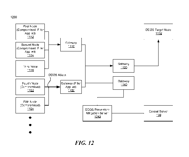
of the received data. A match between the decrypted central-server signature
and the
generated hash value of the data is a confirmation to server 122 that central
server 130 has
deemed the communication from client 112 to be trustworthy. More particularly,
the match is
a confirmation to server 122 that central server 130 has verified that 1)
client 112 is indeed
the sender of the communication, and 2) the data has not been altered since
the data was
signed by client 112.
17
CA 03070415 2020-01-17
WO 2019/018420
PCT/US2018/042524
[86] At an optional step 424, server 122 may verify the client signature
using client
112's public key, which may be stored locally at server 122 or retrieved from
a separate data
store (e.g., data store 142). It may be preferable that server 122's source of
client 112's
public key is different from central server 130's source of client 112's
public key so as to
avoid a single point of failure (e.g., when the source is compromised to an
attack). In system
300, for example, server 122 may verify the client signature by decrypting the
client
signature using client 112's public key and comparing the decrypted client
signature with a
hash value of the received data. A match between the decrypted client
signature and the
hash value of the received data indicates to server 122 that 1) the sender of
the data had
access to client 112's private key 312, and 2) the data has not been altered
since the data
was signed by the sender. If only client 112 is assumed to have access to
client 112's
private key 312, the match may further indicate to server 122 that client 112
is indeed the
sender of the data. If the decrypted client signature and the generated hash
value of the
received data do not match, server 122 may halt process 400. In some
embodiments, if the
decrypted client signature and the generated hash value of the received data
do not match,
server 122 may save the client signature and/or the data for further
examination, for
example, by a system administrator or a security analysis software.
[87] Server 122's verification of the client signature may be performed
independently from central server 130's verification of the client signature
at step 414 so as
to prevent a single point of failure in system 300. For example, server 122
may
independently generate a hash value of the received data without sharing the
hash value
with central server 130 or vice versa. Further, server 122 may retrieve client
112's public key
from a source is not shared with central server 130.
[88] The optional step 424 may be performed any time after the
communication is
received from client 112 at step 408 and before the communication is processed
(or finished
being processed) at step 406. For example, the optional step 424 may be
performed in
parallel with one or more of steps 410-422. In another example, the optional
step 424 may
be performed after verifying the central-server signature 422 or before
transmitting the client
signature and the data to central server 130 at step 410.
[89] In some embodiments, server 122 may further verify that the received
data (or
the content of the communication) is in accordance with policies associated
with system 300.
For example, server 122 may perform one or more verifications that are similar
to the
verifications performed by central server 130 at step 416. In embodiments
where server 122
verifies that client 112 and/or server 122 are listed as being active in a
list of active entities
accessible by central server 130, the list of active entities may be the same
list or a different
list from the list that can be accessed by central server 130. In embodiments
where the list is
18
CA 03070415 2020-01-17
WO 2019/018420
PCT/US2018/042524
different from the list accessible by central server 130, client 112 or server
122 may be
immediately prevented from communicating with other entities in system 100
simply by
altering either the list accessible to server 122 or the list accessible to
central server 130.
[90] In embodiments where a plurality of client signatures is received,
server 122
may verify at least one client signature. Additionally, the client signature
verified by server
122 may be different from the client signature verified by central server 130.
In some
embodiments, server 122 may verify all of the plurality of client signatures.
[91] At step 426, server 122 may process the communication. For example,
server
122 may process the communication after step 422 and/or step 424. In some
embodiments,
server 122 may partially process the communication before step 422 and/or step
424, and
server 122 may finish processing the communication after step 422 and/or step
424. In some
embodiments, server 122 may send an indication to client 112 that the
communication has
been processed.
[92] FIG. 5 is a flow diagram of a process 500 for sending a trusted
communication
from server 122 to client 112 in system 300 of FIG. 3 in which concepts
consistent with the
principles of the invention may be implemented. As shown in FIG. 5, steps 502,
504, 506,
516, 518, and 520 may be implemented by server 122; steps 508, 510, 512, and
514 by
central server 130; and steps 522, 524, and 526 by client 112. In some
embodiments,
however, steps 502, 504, 506, 516, 518, and 520 may be implemented by client
112 and
steps 522, 524, and 526 may be implemented by server 122. In some embodiments,
steps
502, 504, 506, 516, 518, and 520 may be implemented by client 112 and steps
522, 524,
and 526 may be implemented by another client. In some embodiments, however,
steps 502,
504, 506, 516, 518, and 520 may be implemented by server 122 and steps 522,
524, and
526 may be implemented by another server.
[93] At a step 502, server 122 may obtain data to be sent to client 112. In
some
embodiments, the data may be generated by server 122. In some embodiments, the
data
may be obtained by one or more devices or components that are associated with
server 122.
For example, the data may be obtained from an instant messaging system that is
in
communication with server 122 and may include a message destined for client
112. In some
embodiments, the data may be provided by a user of system 300. For example, a
user may
provide data directly to server 122, for example, via a user interface of
server 122.
Alternatively, or additionally, a user may provide data indirectly to server
122, for example,
by causing the data to be transmitted to server 122 or by causing server 122
to retrieve a
user-generated data.
19
CA 03070415 2020-01-17
WO 2019/018420
PCT/US2018/042524
[94] The data may be any data that server 122 has access to. For example,
in
system 200 of FIG. 2, server 122 may obtain data that includes instructions on
how to
configure smart thermostat 112b or a new firmware to be installed in vehicle
230's
entertainment system 112d. In another example, the data may include data for
software
running on the portable device 112c.
[95] In some embodiments, the data may include information identifying the
sender
(i.e., client 112) and/or the intended recipient(s). In some embodiments, the
data may
include a set of data. Further, the set of data may include data obtained from
a plurality of
sources or generated by a plurality of entities.
[96] At a step 504, server 122 may obtain a server signature. In some
embodiments, the server signature may be generated based on at least a portion
of the
obtained data using server 122's private key 322. For example, server 122 may
generate the
server signature by generating a hash value of the data to be sent to client
112 and
encrypting the generated hash with server 122's private key 322. In some
embodiments,
server 122 may generate the server signature by encrypting some or all of the
data to be
sent to client 112.
[97] In system 300, a server signature is a digital signature generated
using server
122's private key 322. However, in some embodiments, the server signature may
be any
information that can be used by client 112 and central server 130 to verify
that the
communication is indeed sent by server 122. For example, the server signature
may be a
passcode associated with server 122. As discussed above, however, a digital
signature is
preferable over the passcode as the passcode may be compromised, for example,
when the
communication is intercepted. The server signature may be generated by server
122.
Alternatively, server 122 may obtain the server signature from another
component such as a
signature processor.
[98] At a step 506, server 122 may transmit the server signature to central
server
130. In some embodiments, server 122 may further transmit the data.
[99] At a step 508, central server 130 may receive the server signature. In
some
embodiments, central server 130 may further receive the data.
[100] At a step 510, central server 130 may verify the server signature. In
some
embodiments, central server 130 may verify the server signature using server
122's public
key 336. In one example, central server 130 may verify the server signature by
generating a
hash value of the received data, decrypting the server signature using server
122's public
key 336, comparing the decrypted signature with the generated hash value of
the received
data. A match between the decrypted server signature and the generated hash
value of the
CA 03070415 2020-01-17
WO 2019/018420
PCT/US2018/042524
received data indicates to central server 130 that 1) the sender of the data
had access to
server 122's private key 322, and 2) the data has not been altered since the
data was signed
by the sender. If only server 122 is assumed to have access to server 122's
private key 322,
the match may further indicate to central server 130 that server 122 is indeed
the sender of
the data. If the decrypted server signature and the generated hash value of
the received
data do not match, central server 130 may halt process 400. In some
embodiments, if the
decrypted server signature and the generated hash value of the received data
do not match,
central sever 130 notify server 122. Alternatively, central server 130 may not
notify server
122. In some embodiments, central server 130 may save the server signature
and/or the
data for further examination, for example, by a system administrator or a
security analysis
software.
[101] At a step 512, central server 130 may obtain a central-server
signature
generated based on at least a portion of the data. In some embodiments, the
central-server
signature may be generate using central server 130's private key 332. For
example, the
central-server signature may be generated by generating a hash value of the
data and
encrypting the hash value with central server 130's private key 332. In some
embodiments,
server 122 may generate the server signature by encrypting some or all of the
data to be
sent to client 112.
[102] In system 300, as discussed above, a central-server signature is a
digital
signature generated using central server 130's private key. However, in some
embodiments,
the central-server signature may be any information that can be used by
clients 110 to
confirm that central server 130 has deemed the data as being trustworthy. For
example, as
discussed above, the central-server signature may be a passcode associated
with central
server 130.
[103] At a step 514, central server 130 may transmit the central-server
signature to
server 122. In some embodiments, central server 130 may further transmit the
data and/or
the server signature to server 122.
[104] In some embodiments, central server 130 may transmit the central-
server
signature after determining that the received data (or the content of the
communication) is in
accordance with policies associated with system 300. For example, central
server 130 may
verify, by accessing a policy server (e.g., policy server 344), that server
122 is authorized to
send a communication to client 112 and/or that client 112 is authorized to
receive a
communication from server 122. In another example, central server 130 may
verify, by
accessing a policy server (e.g., policy server 344), that client 112 and/or
server 122 is not in
any system-wide or global blacklist. A policy may also define, for example, a
time period and
21
CA 03070415 2020-01-17
WO 2019/018420
PCT/US2018/042524
frequency at which client 112 and server 122 may communicate. If central
server 130
determines that the received data is not in accordance with the policies
associated with
system 300, central server 130 may halt process 500.
[105] In some embodiments, central server 130 may transmit the central-
server
signature after inspecting the data. For example, central server 130 may
verify that the data
does not include any known malicious software code or instructions. If
malicious software
code or instructions are detected, central server 130 may halt process 500 in
one example.
[106] In some embodiments, central server 130 may have access to a list of
active
entities in system 300 and may transmit the central-server signature after
verifying that client
112 and/or server 122 are listed as being active. If one or both of client 112
and server 122
are listed as being inactive or missing from the list, central server 130 may
halt process 500.
Therefore, by simply listing client 112 or server 122 as being inactive or
removing client 112
or server 122 from the list, client 112 or server 122 may be immediately
prevented from
communicating with other entities in system 100.
[107] At a step 516, server 122 may receive the central-server signature.
In some
embodiments, server 122 may further receive the data and/or the server
signature.
[108] At an optional step 518, server 122 may obtain a server-group
signature
generated based at least on a portion of the data. In some embodiments, the
server-group
signature may be generated using server group 125's private key 324. For
example, the
server-group signature may be generated by generating a hash value of the data
and
encrypting the hash value with server-group 125's private key 324. In some
embodiments,
server 122 may generate a server-group signature based at least on the data
and the
central-server signature.
[109] In system 300, a server-group signature is a digital signature
generated using
server-group 125's private key 324. However, in some embodiments, the server-
group
signature may be any information that can be used by clients 110 to verify
that the
communication is indeed sent by one of the servers 120 in server group 125.
For example,
the server-group signature may be a passcode associated with server-group 125.
As
discussed above, however, a digital signature is preferable over the passcode
as the
passcode may be compromised, for example, when the communication is
intercepted.
[110] As discussed above in reference to FIG. 3, server group 125's private
key 324
may be stored in data store 142 that may be accessible by each of the server
120 in server
group 125. Therefore, prior to generating the server-group signature, server
122 may
retrieve server group 125's private key 324 from data store 142. In some
embodiments,
server 122 may store a local copy of server group 125's private key 324. In
these
22
CA 03070415 2020-01-17
WO 2019/018420
PCT/US2018/042524
embodiments, server 122 may periodically update the local copy with the
version stored in
data store 142. Alternatively, server 122 may generate a server-group
signature by sending
the data and/or the central-server signature to a signature component and
receiving a
server-group signature generated by the signature component using server group
125's
private key 324 accessible by the signature component. In some embodiments,
the
signature component and the gateway associated with server group 125 may
implemented
on the same entity.
[111] In FIG. 5, step 518 is shown to be performed after step 516. However,
in some
embodiments, step 518 may be performed any time after step 502 and before step
520.
[112] At a step 520, server 122 may transmit a communication to client 112.
The
communication may include the server-group signature and the central-server
signature. In
embodiments where neither of the server-group signature and the central-server
signature is
an encrypted version on the entire obtained data, the communication may
further include the
obtained data.
[113] In some embodiments, server 122 may verify that the data is in
accordance
with policies associated with system 300 prior to transmitting the
communication. For
example, server 122 may verify, by accessing a policy server (e.g., policy
server 344 and/or
another policy server), that client 112 is authorized to send a communication
to server 122
and/or that server 122 is authorized to receive a communication from client
130. A policy
may also define, for example, a time period and frequency at which client 112
and server
122 may communicate. In another example, server 122 may verify, by accessing a
policy
server (e.g., policy server 344 and/or another policy server), that client 112
and/or server
122 is not in any system-wide or global blacklist. A policy may also define,
for example, a
time period and frequency at which client 112 and server 122 may communicate.
If server
122 determines that the received data is not in accordance with the policies
associated with
system 300, server 122 may halt process 500. In some embodiments, server 122
may
further verify that the communication does not include any known malicious
software code or
instructions. If malicious software code or instructions are detected, server
122 may halt
process 500in one example. In some embodiments, server 122 may verify that
client 112
and/or server 122 are listed as being active in a list of active entities
accessible by server
122. If one or both of client 112 and server 122 are listed as being inactive
or missing from
the list, server 122 may halt process 500. Therefore, by simply listing client
112 or server
122 as being inactive or removing client 112 or server 122 from the list,
client 112 or server
122 may be immediately prevented from communicating with other entities in
system 100.
The list of active entities may be the same or different list that can be
accessed by central
23
CA 03070415 2020-01-17
WO 2019/018420
PCT/US2018/042524
server 130. In some embodiments, instead of the server-group signature, the
communication
may include the server signature (e.g., when the system includes only one
server 122).
[114] At a step 522, client 112 may receive the communication.
[115] At a step 524, client 112 may verify the server-group signature and
the central-
server signature. In some embodiments, client 112 may verify the central-
server signature
using central server 130's public key 314. In one example, client 112 may
verify the central-
server signature by generating a hash value of the data included in the
communication,
decrypting the central-server signature using central server 130's public key
314, comparing
the decrypted signature with the generated hash value of the data. A match
between the
decrypted central-server signature and the generated hash value of the data
indicates to
client 112 that central server 130 has deemed the data included in the
communication to be
trustworthy. More particularly, the match indicates to client 112 that central
server 130 has
verified that 1) one of the servers 120 in server group 125 is indeed the
sender of the
communication, and 2) the data has not been altered since the data was signed
by server
122. If the decrypted central-server signature and the generated hash value of
the data do
not match, client 112 may halt process 500.
[116] Client 112 may verify the server-group signature using server group
125's
public key 324. In one example, client 112 may verify the server-group
signature by
generating a hash value of the data included in the communication, decrypting
the server-
group signature using server group 125's public key 324, comparing the
decrypted signature
with the generated hash value of the data. A match between the decrypted
server-group
signature and the generated hash value of the data may provide a confirmation
to client 112
that 1) the data included in the communication is from one of the servers 120
in server group
125, and 2) the data has not been altered since the data was signed by server
122. If the
decrypted server-group signature and the generated hash value of the data do
not match,
client 112 may halt process 500.
[117] In some embodiments, instead of the server-group signature, server
122 may
have transmitted the server signature to client 112 at step 520 instead of the
server-group
signature. In these embodiments, client 112 may have access to public keys of
servers 120
and verify the received server signature using server 122's public key.
However, it is
preferable that server 122 generate and transmit a server-group signature, as
opposed to a
server signature, because each client 112 only needs to have access to and/or
manage a
single server group 125's public key 316 (in addition to its own private key
and central server
130's public key). In embodiments where a server signature is transmitted to
client 112,
instead of a server-group key, each client may need to manage public keys of
all servers
24
CA 03070415 2020-01-17
WO 2019/018420
PCT/US2018/042524
120 that client 112 can communicate with. In some systems, however, clients
110 may not
have the capability to store and/or manage a large number of keys. For
example, in an loT
system (e.g., system 200), clients 110 may be implemented on low-power and
small devices
(e.g., smart thermostat 112b) that does not have sufficient storage capacity
and/or
processing power to store and/or manage a large number of keys.
[118] In some embodiments, if client 112 halts process 500 because the
verification
of one or both of the signatures has failed, the signatures and/or the data
may be stored for
future examination, for example, by a system administrator or a security
analysis software.
[119] At step 526, client 112 may process the communication. In some
embodiments, client 112 may partially process the communication before step
524, and
server 122 may finish processing the communication after step 524. In some
embodiments,
client 112 may send an indication to server 122 that the communication has
been
processed.
[120] In some embodiments after obtaining data at 502, server 122 may
transmit the
data and/or the server 122's signature generated at step 504 to at least one
entity other than
central server 130 (e.g., another server or central server). In these
embodiments, each of
these entities, after verifying that the data is trustworthy using its own
verification process,
may generate a digital signature using each its own private key and transmit
the digital
signature to server 122. Server 122, at step 506, may transmit these digital
signatures to
central server 130. Alternatively, these digital signature may be transmitted
to central server
130 directly. Further, at step 510, central server 130 may further verify
these digital
signatures before transmitting the central-server signature to server 122.
Automated Mutual Authentication
[121] FIG. 6 is a flow diagram of a process 600 for transmitting an
approval request
from client 112 to be approved by server 122 and central server 130 in which
concepts
consistent with the principles of the invention may be implemented. As shown
in FIG. 6,
steps 602, 604, 606, 630, 632, and 634 may be implemented by client 112, steps
608, 610,
620, 622, 624, 626, and 628 by server 122, and steps 612, 614, 616, 618 by
central server
130. In some embodiments, steps 602, 604, 606, 630, 632, and 634 may be
implemented by
server 122, steps 608, 610, 620, 622, 624, 626, and 628 by client 112. In some
embodiments, steps 602, 604, 606, 630, 632, and 634 may be implemented by
server 122,
steps 608, 610, 620, 622, 624, 626, and 628 by another server. In some
embodiments, steps
602, 604, 606, 630, 632, and 634 may be implemented by client 112, steps 608,
610, 620,
622, 624, 626, and 628 by another client.
CA 03070415 2020-01-17
WO 2019/018420
PCT/US2018/042524
[122] At a step 602, client 112 may prepare an approval request. An
approval
request may be prepared by client 112 when client 112 needs an approval from
server 122
before taking an action. For example, the approval request may be a user
authentication
request when a user is attempting to login to client 112; the user
authentication request may
include authentication information of a user such as user identifying
information, password
(encrypted or in clear text), login date and time, and requested duration of
the approval.
[123] Steps 604-624 are similar to steps 404-424 of FIG. 4, except that the
data in
steps 602-610 is a request. Steps 626-632 are similar to steps 518-524 of FIG
.5, except
that the data in steps 626 and 628 is the request prepared at step 602.
[124] Furthermore, at one or both of steps 614 and 624, server 122 and/or
central
server 130 may independently determine whether the request should be approved.
In some
embodiments, the determination on whether the request should be approved may
include
accessing one or more policy servers (e.g., policy server 144). For example,
if the request is
an authentication request for a user to login to client 112, the determination
on whether the
request should be approved may include querying one or more policy servers to
determine
whether the user is an authorized user of client 112, server-group 125, and/or
system 300.
[125] At a step 634, client 112 may determine that the request is approved.
In some
embodiments, the determination that the request is approved may cause another
process to
be started. For example, in if the request was an authentication request for a
user to login to
client 112, a process for logging in the user to client 112 may begin.
[126] Process 600 may enable automated communications between client 112
and
server 122. In an loT systems, for example, it may be necessary for entities
to establish trust
automatically, without human intervention such as entering usernames or
passwords.
Process 600 may enable client 112 and server 122 to digitally sign requests
using their
private key as discussed above, and assert and verify each other's identity
without the need
for usernames, passwords, or other human-assisted methods of establishing
trust.
[127] In some embodiments, as discussed above, process 600 may also provide
two-factor (or multi-factor) authentication. That is, in some embodiments, a
request may be
verified by two or more entities (e.g., server 122 and central server 130)
before the request
is approved. Since it is more difficult for an attacker to breach multiple
entities (e.g., to obtain
their private keys) than breaching a single entity, two-factor authentication
may improve the
overall security of the system.
Adding, Removing, Replacing, or Revoking Keys using Reset Keys (Backup
Authentication)
26
CA 03070415 2020-01-17
WO 2019/018420
PCT/US2018/042524
[128] FIG. 7 illustrates an exemplary system 700 in which concepts
consistent with
the principles of the invention may be implemented. System 700 is similar to
system 300 of
FIG. 3, except that system 700 is capable of remotely adding, removing,
revoking, and/or
replacing the keys that can be accessed by clients 110,servers 120, and/or
central server
130. Further, entities in system 700 may have access to (or a copy of) at
least one reset
public key 702. In some embodiments, a single copy of reset public key 702 may
be shared
by a plurality of entities. Alternatively, each entity may have access to its
own copy of reset
public key 702. In some embodiments, entities in system 700 may have access to
(or a copy
of) a plurality of reset public keys. In some embodiments, entities in system
700 may have
access to (or a copy of) three reset public keys. In system 700, an entity
that receives a
communication that is encrypted or signed with a reset private key(s)
corresponding to the
reset public key 702 may store one or more keys included in the communication
so that the
keys can be accessed by the entity. Further, the communication may cause one
or more
keys that are currently accessible by the entity to be revoked and/or removed.
In some
embodiments, the communication may cause one or more keys that are currently
accessible
by the entity to be replaced with the keys that are included in the
communication. For
example, the communication may cause server group 125's public key, central
server 130's
public key, and/or reset public key 702 to be replaced with the keys included
in the
communication.
[129] In some embodiments, such a communication may be used to replace
server
group 125's public key and/or central server 130's public key periodically or
when requested
by a user (e.g., system administrator). In some embodiments, such a
communication may be
used to replace server group 125's public key and/or central server 130's
public key when a
server 122 and/or central server 130 is determined to be compromised. In some
embodiments, such a communication may be used to replace server group 125's
public key
and/or central server 130's public key when server group 125's private key
and/or central
server 130's private key are determined to be compromised (e.g., a backup file
containing
the private keys is lost). In some embodiments, such a communication may be
used to
replace server group 125's public key and/or central server 130's public key
when an entity
is retired, replaced, moved, or altered. For example, such a communication may
be used to
replace server group 125's public key and/or central server 130's public key
when a server
122 and/or central server 130 is updated with a new hardware or software.
[130] FIG. 8 is a flow diagram of a process 800 for adding, removing,
revoking,
and/or replacing digital keys accessible by various entities in system 700 in
which concepts
consistent with the principles of the invention may be implemented.
27
CA 03070415 2020-01-17
WO 2019/018420
PCT/US2018/042524
[131] At a step 802, an entity (e.g., client 112, server 122, or central
server 130) of
system 700 may receive a communication. The communication may include at least
one
digital signature generated using at least one private key and at least one
new key. In some
embodiments, the communication may include a digital signature that is
generated using a
plurality of reset private keys. For example, an intermediate digital
signature may be
generated using a first reset private key, and a final digital signature may
be generated using
a second reset private key based on the intermediate digital signature. In
some
embodiments, the communication may include a plurality of digital signatures
generated
using a plurality of reset private keys. The communication may be transmitted
from any one
of clients 110, servers 120, and central server 130. Alternatively, the
communication may be
transmitted from another entity in or outside system 700.
[132] The new keys included in the communication may include, for example,
at least
one of reset public keys, central server 130's public key 313, server group
125's public key
316, client 122's private key, and server 122's private key. One or more of
the new keys
(e.g., private keys) may be encrypted before being included in the
communication. In some
embodiments, new keys included in the communication may include a plurality of
reset
public keys. In some embodiments, new keys included in the communication may
include
three reset public keys.
[133] At a step 804, the entity may verify the digital signature using at
least one reset
public key 702 accessible by the entity. Verifying the digital signature may
include verifying
that the digital signature was generated by a reset private key that
corresponds to the reset
public key 702. In embodiments where the digital signature is generated using
a plurality of
reset private keys, the digital signature may be verified using a plurality of
public keys that
correspond to the plurality of reset private keys in an order that was signed
using the
plurality of reset private keys. In the above example where an intermediate
digital signature
is generated using a first reset private key and a final digital signature is
generated using a
second reset private key based on the intermediate digital signature, the
final digital
signature may be first decrypted using a second public key corresponding to
the second
reset private key and the subsequently decrypted using a first public key
corresponding to
the first reset private key. In embodiments where a plurality of digital
signatures are
received, a plurality of reset public keys 702 may be used to verify the
plurality of digital
signatures.
[134] At a step 806, the entity may store the new key(s) included in the
communication so that the new key(s) may be accessible by the entity. In some
embodiments, the new key(s) may be stored in the entity or in a separate
storage
component accessible by the entity. In some embodiments, the entity may load
the new key
28
CA 03070415 2020-01-17
WO 2019/018420
PCT/US2018/042524
to a signature processor accessible by the entity. In some embodiments, the
new key(s) may
replace the keys that are currently accessible by the entity. At an optional
step, the entity
may revoke or remove one or more keys that are accessible by the entity. In
some
embodiments, the entity may prevent future access to the revoked keys. In some
embodiments, the communication may further include a reset instruction that
identifies the
new keys included in the communication as wells the keys to be revoked,
removed, or
replaced.
[135] In some embodiments, at step 804, the entity may receive a
communication
that includes at least one digital signature generated using at least one
private key without
any new keys. In these embodiments, after verifying the digital signature at
step 804, the
entity may remove or revoke one or more keys that are accessible by the entity
without
adding new keys. The communication may include a reset instruction that
identifies the keys
to be removed or revoked.
[136] In some embodiments, the entity's ability to add, remove, replace, or
revoke
keys may depend on the private key that was used to generate the digital
signature. For
example, when the entity receives a digital signature generated using a first
private key, the
entity may be allowed to add new keys. However, if the entity receives a
digital signature
generated using a second private key, the entity may be allowed to add new
keys and
remove the keys that are currently accessible to the entity. In another
example, if the entity
receives a digital signature generated using a third private key, the entity
may only be
allowed to add public keys, but not private keys.
[137] At an optional step, the entity may notify the sender of the
communication that
the new keys have been added.
Identity Abstraction
[138] FIG. 9 illustrates a system 900 in which concepts consistent with
principles of
the invention may be implemented. System 900 includes a group of clients 910
that includes,
for example, clients 912 and 914, and a group of servers 920 that includes,
for example,
servers 922 and 924. At least some of the communications between clients in
group of
clients 910 and servers in group of servers 920 may be signed communications
that include
digital signatures.
[139] In conventional systems, a client that can receive signed
communications from
a plurality of servers requires a public key for each server in the plurality
of servers. For
example, if a client communicates with a group of servers that includes
thousands of
servers, the client would need to have access to the thousands of server
public keys. In
some systems, however, clients may not have the capability to store and/or
manage a large
29
CA 03070415 2020-01-17
WO 2019/018420
PCT/US2018/042524
number of keys. For example, in an loT system, clients may be implemented on
low-power
and small devices that do not have sufficient storage capacity and/or
processing power to
store and/or manage a large number of keys.
[140] In contrast, clients 910 in system 900 may require a single public
key
associated with group of servers 920. For example, in system 900, servers in
group of
servers 920 (e.g., servers 922 and 924) may send communications to clients in
group of
clients 910 that includes a digital signature generated using a common private
key (i.e.,
server group's private key 942) that can be accessed by the servers in group
of servers 920.
Thus, clients 910 require a single public key that corresponding to the common
private key
(i.e., server group's public key 944) to verify the included digital signature
signed by servers
in group of server 920. Server group's private key 942 may be stored in each
server.
Alternatively, server group's private key 942 may be stored in a shared
storage.
[141] FIG. 10 is a flow diagram of a process 1000 for transmitting
digitally signed
communications by a server 922 in a group of servers 920 in system 900 of FIG.
9.
[142] At a step 1002, server 922 may obtain access to a private key 942
associated
with server group 920. In some embodiments, server 922 may obtain access to
private key
942 by being authenticated by another entity. For example, server 922 may
obtain access to
private key 942 by sending a digital signature generated using server 922's
private key to an
authentication server. In this example, the authentication, after verifying
the digital signature,
may authorize server 922 to access private key 942.
[143] At a step 1004, server 922 may generate a digital signature using
private key
942. The digital signature may be based on data to be transmitted to client
912. Client 912
may be one of a plurality of clients (e.g., clients in group of clients 910)
that may
communicate with servers in group of servers 920, including server 922.
[144] At a step 1006, server 922 may transmit a communication to client
912. The
communication may include the data to be transmitted to client 912 and the
generated digital
signature.
[145] At a step 1008, client 912, after receiving the communication from
server 922,
may verify the digital signature included in the communication using a public
key 944 that
corresponds to the private key 942. In some embodiments, clients in group of
clients 910
may have access to the public key.
[146] At a step 1010, client 912 may verify the digital signature.
CA 03070415 2020-01-17
WO 2019/018420
PCT/US2018/042524
[147] At a step 1012, client 912, after verifying the digital signature,
may process the
communication. In some embodiments, client 912, after verifying the digital
signature, may
finish processing the communication.
[148] Preventing and/or Mitigating DDOS Attacks
[149] FIG. 11 illustrates an example of a conventional system 1100. As
shown in
FIG. 11, system 1100 includes a number of nodes and a number of gateways. For
example,
system 1100 includes first node 1112, second node 1114, and third node 1116,
which are
connected to a gateway 1110, and system 1100 further includes fourth node 1122
and fifth
node 1124, which are connected to a gateway 1120. System 1100 may further
include a
DDOS target node 1132 connected to a gateway 1130. Although not shown in FIG.
11,
system 1100 may be a system, such as an loT system, that includes, for
example, millions of
additional nodes and gateways.
[150] As used herein, a "node" may be any physical or virtual entity
capable of
communicating via a computer network. For example, a node may be a physical
computer,
piece(s) of software, internet-of-things device, internet-of-things
hub/bridge, virtual machine,
server, printer, gateway, router, switch, smartphone/cellular phone, smart
watch, tablet, or
combination thereof. In some embodiments, a plurality of nodes may be
implemented on a
single physical or virtual device. Alternatively, or additionally, a single
node may be
implemented on a plurality of physical and/or virtual devices. As used herein,
a "gateway"
may be a node that connects at least one set of nodes to at least one other
set of nodes.
[151] In the example of FIG. 11, at least some of the nodes in system 1100,
including
for example, first node 1112, second node 1114, and fourth node 1122, and
fifth node 1124,
may be compromised (e.g., by malware, virus, injection attack, rogue firmware,
or other
means). Further, the compromised nodes may be configured to inundate a DDOS
target
node 1132 with communications. Such communications may be intended to overload
DDOS
target node 1132 so as to prevent DDOS target node 1132 from operating
normally. While
communications from several nodes may not be sufficient to prevent DDOS target
node
1132 from operating normally, communications from hundreds or thousands of
nodes may
exceed the capability of DDOS target node 1132 to process incoming
communications.
Accordingly, DDOS target node 1132 may become unavailable to process
legitimate,
incoming communications.
[152] In one example, DDOS target node 1132 may be a server providing data
to a
smartphone app. In this example, thousands of nodes in system 1100 may be
infected by a
Trojan virus programmed to simultaneously transmit communications to the
server (i.e.,
DDOS target node 1132). As a result, the overloaded server may become
unavailable to
31
CA 03070415 2020-01-17
WO 2019/018420
PCT/US2018/042524
provide data to the smartphone app, preventing the smartphone app to operate
normally. In
another example, DDOS Target Node 1132 may be a DNS or an NTP server. In this
example, thousands of nodes in system 1100 may be infected by a malware
programmed to
simultaneously attempt resolving the name of a site or a server or obtain an
update for the
current time. The overloaded servers may not be able to respond to legitimate
queries or
legitimate request for an updated time (e.g., when daylight saving begins or
ends).
[153] In conventional system 1100, a communications filter may be
implemented on
DDOS target node 1132 and/or on a node near DDOS target node 1132 (e.g.,
gateway
1130). The filter may be configured to identify and prevent communications
originating from
compromised nodes. However, in situations where thousands of compromised nodes
are
sending communications destined for DDOS target node 1132, even the filter may
be
overloaded by the communications originating from the compromised nodes.
Accordingly, an
effective strategy for preventing and/or mitigating DDOS attacks may include
filtering the
communications at the source nodes and/or nodes near the source nodes.
[154] FIG. 12 illustrates an example of a system 1200 for preventing and/or
mitigating DDOS attacks in accordance with the disclosed embodiments. System
1200 is
similar to system 1100 of FIG. 11, except system 1200 further includes a DDOS
prevention/
mitigation server 1242, central server 130 (similar to central server 130 of
FIG. 3), and
gateway 1140. As shown in FIG .12, gateway 1140 connects DDOS prevention /
mitigation
server 1242 to the nodes. Further, central server 130 may be connected to DDOS
prevention / mitigation server 1242. In some embodiments, central server 130
may be
connected to gateway 1140 and communicate with DDOS prevention / mitigation
server
1242 via gateway 1140.
[155] Additionally, one or more potentially compromised nodes and/or
gateways
(e.g., first node 1112, second node 1114, and gateway 1120) may each implement
a
communications filter that prevents transmission and/or processing (e.g.,
routing) of
communications involving nodes identified in a blacklist. For example, a
communications
filter on first node 1112 and second node 1114 may prevent transmission of
communications
destined for nodes identified in the blacklist. In another example, a
communications filter on
gateway 1120 may prevent routing of communications destined for nodes
identified in the
blacklist. In yet another example, a communications filter on a recursive DNS
server (not
shown) may prevent the recursive DNS server from responding to DNS queries
that require
queries to authoritative DNS servers identified in the blacklist.
[156] Alternatively, or additionally, the communications filter may prevent
transmission and/or processing of communications that do not involve at least
one of the
32
CA 03070415 2020-01-17
WO 2019/018420
PCT/US2018/042524
nodes identified in a whitelist. For example, a communications filter on first
node 1112 and
second node 1114 may prevent transmission of communications destined for nodes
that are
not identified in the whitelist. In another example, a communications filter
on gateway 1120
may prevent routing of communications destined for nodes that are not
identified in the
whitelist. In yet another example, a communications filter on a recursive DNS
server (not
shown) may prevent the recursive DNS server from responding to DNS queries
that require
queries to authoritative DNS servers that are not identified in the whitelist.
That is, a
communications filter on a recursive DNS server (not shown) may only allow the
recursive
DNS server to respond to DNS queries that require queries to authoritative DNS
servers that
are identified in the whitelist.
[157] In some embodiments, the blacklist may identify nodes that are
compromised
and/or are targets of a DDOS attack or a potential DDOS attack. In some
embodiments, the
whitelist may identify authorized destination nodes. For example, the
whitelist may identify
nodes that are known to interact with the source node and/or nodes associated
with the
gateway. Accordingly, the communications filters may prevent communications
intended to
overload DDOS target node 1132 from being transmitted and/or processed at the
source
node or on nodes near the source nodes. In the example of FIG. 12, compromised
nodes
such as first node 1112 and second node 1114 may be prevented from
transmitting
communications intended to overload DDOS target node 1132. Further, gateway
1120 may
prevent communications from compromised nodes such as fourth node 1122 and
fifth node
1124 from being routed to DDOS target node 1132.
[158] In system 1200, DDOS prevention / mitigation server 1242 may provide
the
nodes implementing communications filters with the blacklist and/or whitelist.
In some
embodiments, DDOS prevention / mitigation server 1242 may generate the
blacklist and/or
whitelist. In some embodiments, DDOS prevention / mitigation server 1242 may
generate
the blacklist and/or whitelist based on data from another node or based on
aggregated data
from one or more nodes. For example, DDOS prevention / mitigation server 1242
may
generate the blacklist and/or whitelist based on a result of a network
security analysis
performed by another node. In some embodiments, DDOS prevention / mitigation
server
1242 may obtain the blacklist and/or whitelist from another node.
[159] In some embodiments, DDOS prevention / mitigation server 1242 may
generate the blacklist and/or whitelist based on data obtained from various
nodes in system
1200. For example, DDOS prevention / mitigation server 1242 may generate the
blacklist
and/or whitelist based on network data obtained from first node 1112, second
node 1114,
third node 1116, fourth node 1122, fifth node 1124, gateway 1110, gateway
1120, gateway
1130, or a combination thereof. In some embodiments, the network data may
include data
33
CA 03070415 2020-01-17
WO 2019/018420
PCT/US2018/042524
derived from historical, current, and/or predicted network traffic data. In
one example, DDOS
prevention / mitigation server 1242 may generate a blacklist that includes
nodes that are
currently experiencing an amount of network traffic that exceeds the
historical-average
network traffic by a predetermined percentage. In some embodiments, DDOS
prevention /
mitigation server 1242 may generate/modify the black and/or whitelist based on
network
analysis from nodes in specific geographic regions, companies, device types
(specific
model, or types of devices like cameras or network video recorders),
environments (SCADA,
ICS, M2M, etc.). In some embodiments, DDoS prevention / mitigation server 1242
may
generate/modify the black and/or whitelist based on external sources (e.g.,
trusted lists from
other vendors, government threat notifications, or other sources).
[160] In some embodiments, the network data may be provided to DDOS
prevention
/ mitigation server 1242 using trusted communications. In one example, a node
may provide
the network data to DDOS prevention and mitigation server 1242 using process
400
described above with respect to FIG. 4. In this example, DDOS prevention and
mitigation
server 1242 may implement functions of server 122, and the node may implement
functions
of client 112. In another example, a node may provide the network data to DDOS
prevention
and mitigation server 1242 using process 500 described above with respect to
FIG. 5. In this
example, DDOS prevention and mitigation server 1242 may implement functions of
client
112, and the node may implement functions of server 122.
[161] In some embodiments, the network data from various nodes in system
1200
may be provided to a gateway, and the gateway may provide the network data
from the
nodes, and/or data derived from the network data from the nodes, to DDOS
prevention /
mitigation server 1242. In these embodiments, the nodes may provide the
network data to
the gateway using trusted communications (e.g., using processes 400 and/or 500
of FIGS. 4
and 5, respectively). Additionally, or alternatively, the gateway may provide
the network data
and/or data derived from the network data to DDOS prevention / mitigation
server 1242
using trusted communications (e.g., using processes 400 and/or 500 of FIGS. 4
and 5,
respectively).
[162] In some embodiments, DDOS prevention / mitigation server 1242 may
provide
the nodes implementing communications filters with updates to the blacklist
and/or whitelist.
In some embodiments, the updates may be provided periodically or when the
blacklist and/or
whitelist are altered. In some embodiments, the updates to the blacklist
and/or whitelist may
be provided to the nodes using trusted communications (e.g., using processes
400 and/or
500 of FIGS. 4 and 5, respectively).
34
CA 03070415 2020-01-17
WO 2019/018420
PCT/US2018/042524
[163] In system 1200, DDOS prevention / mitigation server 1242 may provide
the
blacklist and/or whitelist to various nodes using trusted communications.
Providing the
blacklist and/or the whitelist using trusted communications may prevent
attackers from
providing an unauthorized blacklist and/or whitelist to various nodes in an
attempt to defeat
the communications filters. In one example, DDOS prevention and mitigation
server 1242
may provide the blacklist and/or whitelist to a node using process 400
described above with
respect to FIG. 4. In this example, DDOS prevention and mitigation server 1242
may
implement functions of client 112, and the node may implement functions of
server 122. In
another example, DDOS prevention and mitigation server 1242 may provide the
blacklist
and/or whitelist to a node using process 500 described above with respect to
FIG. 5. In this
example, DDOS prevention and mitigation server 1242 may implement functions of
server
122, and the node may implement functions of client 112.
[164] FIG. 13 illustrates an example of a process 1300 for mitigating
and/or
preventing DDOS attacks in accordance with the disclosed embodiments.
[165] At a step 1302, a gateway may obtain network data from one or more
entities
associated with the gateway. For example, the entities associated with the
gateway may
include nodes that are connected to the gateway. In some embodiments, the
network data
may include data derived from historical, current, and/or predicted network
traffic data
available to the one or more entities associated with the gateway.
[166] In some embodiments, the one or more entities may implement functions
of
client 112, and the gateway may implement functions of server 122 in system
300 of FIG. 3.
Further, the one or more entities and the gateway may implement process 400 of
FIG. 4 to
communicate with each other (e.g., to provide and obtain the network data).
Alternatively, or
additionally, the one or more entities may implement functions of server 122,
and the
gateway may implement functions of client 112 in system 300 of FIG. 3.
Further, the one or
more entities and the gateway may implement process 500 of FIG. 5 to
communicate with
each other (e.g., to provide and obtain the network data).
[167] At a step 1304, the gateway may provide the network data to DDOS
prevention
/ mitigation server 1242. In some embodiments, the gateway may provide the
network data
to a server associated with DDOS prevention and mitigation server 1242. For
example, the
gateway may provide the network data to a server that analyzes the network
data and
provides a result of the analysis to DDOS prevention and mitigation server
1242.
[168] In some embodiments, the gateway may implement functions of client
112, and
DDOS prevention / mitigation server 1242 may implement functions of server 122
in system
300 of FIG. 3. Further, the gateway and DDOS prevention / mitigation server
1242 may
CA 03070415 2020-01-17
WO 2019/018420
PCT/US2018/042524
implement process 400 of FIG. 4 to communicate with each other (e.g., to
provide and
obtain the network data). Alternatively, or additionally, the gateway may
implement functions
of server 122, and DDOS prevention / mitigation server 1242 may implement
functions of
client 112 in system 300 of FIG. 3. Further, the gateway and DDOS prevention!
mitigation
server 1242 may implement process 500 of FIG. 5 to communicate with each other
(e.g., to
provide and obtain the network data).
[169] At a step 1306, the gateway may obtain a set of entity identifiers
from DDOS
prevention and mitigation server 1242. The set of entity identifiers may be,
for example, a
blacklist and/or a whitelist. The blacklist may identify, for example, nodes
that are
determined by DDOS prevention and mitigation server 1242 as being targets or
potential
targets of a DDOS attack. A target of a DDOS attack may include, for example,
nodes that
are currently being attacked. A potential target of a DDOS attack may include,
for example,
nodes that may be attacked in the future and/or nodes that are probably being
attacked.
[170] The whitelist may identify, for example, nodes that identifies
entities that are
determined by DDOS prevention and mitigation server 1242 as being trusted
entities. Entity
identifiers may include, for example, IP addresses, domain names, MAC
addresses that are
associated with one or more entities.
[171] In some embodiments, the set of entity identifiers may be generated
based on
at least the network data obtained at step 1302. For example, DOS prevention /
mitigation
server 1242 may generate a blacklist that includes nodes that are currently
experiencing a
network traffic that exceeds the historical average network traffic by a
predetermined
percentage.
[172] In some embodiments, DDOS prevention and mitigation server 1242 may
implement functions of client 112, and the gateway may implement functions of
server 122 in
system 300 of FIG. 3. Further, DDOS prevention and mitigation server 1242 and
the
gateway may implement process 400 of FIG. 4 to communicate with each other
(e.g., to
provide and obtain the set of entity identifiers). Alternatively, or
additionally, DDOS
prevention and mitigation server 1242 may implement functions of server 122,
and the
gateway may implement functions of client 112 in system 300 of FIG. 3.
Further, DDOS
prevention and mitigation server 1242 and the gateway may implement process
500 of FIG.
to communicate with each other (e.g., to provide and obtain the set of entity
identifiers).
[173] At a step 1308, the gateway may filter communications based on the
set of
entity identifiers. For example, the gateway may reject communications
destined for the
entities that are included in the blacklist. In another example, the gateway
may reject
communications that are destined for entities that are not included the
whitelist.
36
CA 03070415 2020-01-17
WO 2019/018420
PCT/US2018/042524
[174] While
illustrative embodiments have been described herein, the scope of any
and all embodiments having equivalent elements, modifications, omissions,
combinations
(e.g., of aspects across various embodiments), adaptations and/or alterations
as would be
appreciated by those skilled in the art based on the present disclosure. The
limitations in the
claims are to be interpreted broadly based on the language employed in the
claims and not
limited to examples described in the present specification or during the
prosecution of the
application. The examples are to be construed as non-exclusive. Furthermore,
the steps of
the disclosed routines may be modified in any manner, including by reordering
steps and/or
inserting or deleting steps. It is intended, therefore, that the specification
and examples be
considered as illustrative only, with a true scope and spirit being indicated
by the following
claims and their full scope of equivalents.
37