Note: Descriptions are shown in the official language in which they were submitted.
CA 03070899 2020-01-23
WO 2019/020867
PCT/F12018/050553
SUPPORT FOR A MARKER POLE
TECHNICAL FIELD
The invention relates to a support for a marker pole as defined in the pre-
amble of claim 1.
BACKGROUND OF THE INVENTION
Different kinds of marker poles are used for marking areas and paths in
sports fields and orienteering competitions, for example. An important ex-
ample of the use of marker poles are snow poles.
Snow poles are used for marking the edges of roads and yard areas. If no
snow poles are used, it is possible that, after a snow storm, the driver of a
snow plowing or blowing tractor cuts a corner on the road, across a ditch,
for example, or destroys plantings in yards. Earlier, wood sticks, such as
trimmed spruce saplings, were used as snow poles. The current snow poles
are usually brightly-colored round plastic tubes.
A common solution for installing a snow pole is to simply stick it into soft
ground in an upright position. If the ground is hard, a hole may have to be
made in the ground by means of a digging bar. Once the snow pole has been
inserted into the hole, the soil must be compacted around the pole by stomp-
ing by foot. If the snow pole is to be installed in an asphalt-covered area, a
hole matching the diameter of the pole is drilled in the asphalt. Children
playing in the yards of high-rise buildings often pull out snow poles to play
with them. The holes emerging from under the snow in the spring are ugly
and may expand if the asphalt crumbles.
A snow pole driven directly into the ground or asphalt ruptures easily during
collision, such as if a car backs against it. Plastic poles are especially
prone
to rupture in frost weather.
The other kinds of marker poles suffer from the same drawbacks as the snow
poles of the prior art.
CA 03070899 2020-01-23
WO 2019/020867
PCT/F12018/050553
2
US3016035 and US3067717 represent the prior art.
OBJECTIVES OF THE INVENTION
An objective of the invention is to eliminate the above-mentioned draw-
backs of the prior art. A particular objective of the invention is to provide
a
novel general-purpose marker pole support operable in both uncovered and
asphalt-covered ground. The invention aims at providing a faster and easier
way to install marker poles, avoiding the need to use a digging bar and to
compress the soil by stomping by foot. The invention also aims at protecting
the pole from rupturing during collision. Further, the invention aims at fix-
ing the marker pole in the ground in such a way that it is difficult for a
child
to pull it out of the ground. Further, the invention aims at providing the
marker pole with a loop or a fixing member, as a part of the marker pole
support, in order to allow the marker pole to be converted into a fence pole
by means of wires running through the loops.
DESCRIPTION OF THE INVENTION
As for the characteristics of the marker pole support according to the inven-
tion, reference is made to claim 1.
The principal parts of the marker pole support are a ground spike and a
marker pole holder. The ground spike is a straight and narrow rod manually
insertable even into hard ground easier than the marker pole itself No dig-
ging bar or stomping by foot is needed. The marker pole holder is a spiral
similar to a helical spring. At the top of the spiral, the spiral has, over
one
or more of its turns, an inner diameter capable of easily receiving the marker
pole but without any unnecessary clearance. At the bottom of the spiral, the
inner diameter provides a tight fit for the marker pole. When the marker
pole support is in use, there is a substantially horizontal section between
the
ground spike and the spiral. For small-diameter marker poles, the ground
spike is located on the center axis of the spiral. This ensures minimum risk
of buckling for the combination of the marker pole and its support during
installation. Marker poles with a larger diameter have a smaller risk of buck-
ling but a long horizontal section may flex too much during installation.
Therefore, the horizontal section of these larger-diameter marker poles is
made short enough to allow the ground spike to be located away from the
CA 03070899 2020-01-23
WO 2019/020867
PCT/F12018/050553
3
center axis of the spiral, close to the outer margin of the spiral. A vertical
section not wound into a spiral is provided between the horizontal section
and the bottom of the spiral.
If there is uncovered ground at the application site of the marker pole, the
marker pole is installed at the application site as follows, by using a marker
pole support according to the invention: first, the marker pole is inserted
into the spiral of the marker pole support, as far down as it goes
effortlessly.
The uppermost turn, or the uppermost turns, of the spiral serve as a guide
for the pole, the pole being fixed in place at the beginning of the smallest-
diameter turns of the spiral. Then, the marker pole with its support is put in
an upright position, at a desired spot on the ground, and pushed directly
downwards until the ground spike is completely embedded in the ground
and stopped by the horizontal section, and the snow pole is sunk down into
its spiral and stopped by the horizontal section. The uppermost turn of the
spiral serving as a guide is a great help in this operation.
If desired, the marker pole can be inserted into its support prior to driving
the combination into the ground. This is easily done by supporting the hor-
izontal section of the marker pole support on a stair step or the like, for
example, and, then, by pushing the marker pole down into its spiral.
If the marker pole is hit by something, the marker pole will not rupture be-
cause the vertical section between the bottom of the spiral and the horizontal
section is elastic. After the hit, the pole will reassume its upright position
by itself.
If there is asphalt at the application site of the marker pole, a hole
matching
the size of the outer diameter of the marker pole is no longer needed in the
asphalt. When using the marker pole support according to the invention, a
hole suitable for its ground spike is enough. The suitable hole can easily be
drilled in the asphalt by means of a cordless drill, for example. If it is
desir-
able to lock the ground spike in its hole, urethane foam, for example, can
be sprayed into the hole to serve as an adherent prior to pushing the ground
spike into place. Typically, overcoming this kind of adhesion is impossible
for a child but possible for an adult. Neither can a child cannot pull the
pole
out of its spiral. As the marker pole is inserted into the spiral, it
compresses
the spiral, with the result that the diameter of the spiral increases and the
CA 03070899 2020-01-23
WO 2019/020867
PCT/F12018/050553
4
pole slides down into place quite easily. As the marker pole is pulled out of
its spiral, the spiral stretches its length. This reduces the diameter of the
spiral. Therefore, it takes a greater force to pull the marker pole out of its
spiral than to push it in.
LIST OF FIGURES
In the following, the invention will be described in detail with reference to
the accompanying drawing. Figure 1 shows a marker pole support accord-
ing to the invention. Figure 2 shows an accessory for a marker pole support
according to the invention.
DETAILED DESCRIPTION OF THE INVENTION
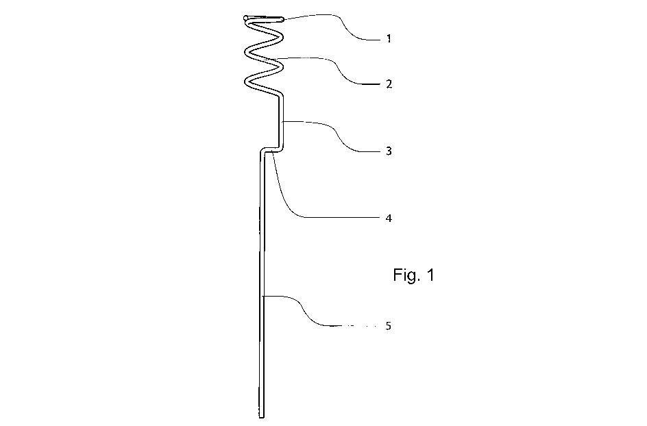
Figure 1 shows a marker pole support according to the invention. It is en-
tirely made of a continuous spring steel wire having a diameter of 4 mm. It
is intended for marker poles which have a nominal outer diameter of 25 mm
and which are used as snow poles. The 25 mm inner diameter of the first
turn 1 of the top of the spiral is such that it easily receives the marker
pole
but without any unnecessary play.
The lower turns of the spiral 2 provide a tight fit for the marker pole, their
inner diameter being 23.5 mm when the marker pole is not inserted into the
spiral. The spiral is extended downwards by a vertical section 3. A horizon-
tal section 4 both stops the marker pole during its insertion into the spiral
and prevents its ground spike 5 from sinking too deep into the ground. Fur-
ther, the horizontal section 4 positions the ground spike on an extension of
center axis of the spiral and the marker pole. This results in that the combi-
nation of the marker pole and the support has less tendency to buckle as the
combination of the pole and the support is pressed down during installation.
The presented solution is applicable as a support not only for marker poles
but also for any similar structures, such as sign, guide, flag and tent-frame
poles.
Figure 2 shows a loop-shaped fixing member 6 which can be formed as part
of the marker pole support. The fixing member 6 can be implemented on
the marker pole 7 with the same operation principle and the same material
CA 03070899 2020-01-23
WO 2019/020867
PCT/F12018/050553
as the marker pole support, in addition to which it does not constitute a part
of the marker pole 7 but an accessory for the marker pole support. Thus, the
marker pole 7 cannot only be positioned and fixed in the ground but also
directly converted into a fence pole by means of the fixing member 6 of the
5 marker pole support since the fixing member allows a wire or a tape to be
tied to the loop 8 and then between any marker poles 7 equipped with a
fixing member 6.
The fixing member 6 for the marker pole can be provided as a spiral around
the marker pole 7. The position of the fixing member 6 on the marker pole
7 can be adjustable such that the spiral comprises a spring-like structure
wherein compressing the turns of the spiral vertically towards each other
increases the inner diameter of the turns and, thus, allows the spiral to be
moved along the marker pole. This may allow for easy manual adjustment
of the height position of the spiral on the marker pole.
The fixing members 6 comprise, as a part of them, a loop 8 or a similar
attachment point for running a wire, tape, electric wire, chain or the like
through or via it in order to install said wire or the like between the marker
.. poles 7 by means of the fixing members 6.
The invention is not restricted to the above-described examples but allows
for many modifications within the inventive idea defined by the claims.