Note: Descriptions are shown in the official language in which they were submitted.
CA 03071298 2020-01-28
1
Apparatus for impregnating fibers having a defined fiber content by volume
Specification
The invention proceeds from an apparatus for impregnating fibers with a matrix
.. material, comprising a unit for soaking the fibers with the matrix
material.
Fiber-composite materials are produced by impregnating fibers. Fibers that
have
been impregnated in a bath can be used in order for components, for example
pipes, masts, or tanks, to be produced by the wet-wrapping method. Such an
.. apparatus permits continuous impregnation of the fibers which can then be
further
processed directly after soaking. The soaked fibers in the wet-wrapping
methods
are usually wound to form the final product prior to the matrix material
having
cured or solidified. Curing or solidifying of the matrix material so as to
form the
final product is then performed post-wrapping.
Various methods are known for soaking fibers, wherein a bath through which the
fibers are guided is typically employed.
For example, it is thus known from US 2,433,965 for endless fibers to be
directed
through a bath in that the fibers are immersed into the bath from above and
are
guided about rollers within the bath. Upon leaving the bath, the fibers thus
soaked
are guided through a pair of rollers in which excess matrix material is
squeezed
out. To this end, the roller pairs are located above the bath surface, so that
the
separated matrix material can flow back into the bath.
An apparatus for producing a wrapped product is known from US 4,267,007. The
fibers prior to the wrapping process herein are likewise soaked in a bath
having
the matrix material. To this end, the fibers are guided about a roller within
the
= bath. The soaked fibers thereafter are directed across a plate and are
pushed
onto the plate by a block in order for excess matrix material to be squeezed
out.
However, all methods in which the fibrous structure is directed through a bath
have the disadvantage that the viscosity of the matrix material by virtue of
the
usually open bath changes over time, either by virtue of evaporation or,
depending
on the matrix material used, also by a chemical reaction by virtue of contact
with
humidity in the air. Moreover, it is necessary for the fibers to be
laboriously
CA 03071298 2020-01-28
2
threaded again after each start-up, for example after a cleaning operation.
Filling
of the bath can only be performed once the fibers have already been placed
therein.
In order to avoid in particular that the viscosity of the matrix material
changes,
methods and apparatuses in which the fibers are guided through a gap in which
the impregnation is performed are known. Such an apparatus is known, for
example, from US 4,937,028, US 5,766,357, or from WO-A 2007/062516, as well
as from A. Miaris et at., "Modeling the Impregnation Process of a Siphon
Impregnation System during Filament Winding", Proceedings of the ASME 2011
Pressure Vessels and Piping Division Conference, PVP2011, July 2011. However,
these methods in particular have the disadvantage that the matrix material by
virtue of the minor size of the impregnation apparatus has be fed continuously
and
in a very precise manner in order for a uniform impregnation to be obtained.
A pultrusion method in which the fibers are guided through ducts into which a
matrix material for soaking is pumped by way of a manifold is known from
US 5,747,075.
US 5,084,305 describes a soaking method in which the fibers are guided across
webs, nozzles by way of which the matrix material is applied to the fibers
being
configured in each of said webs. In that the fibers are guided once along the
top of
a web and once along the bottom of a web, uniform impregnation is achieved in
this system.
A continuous and in particular uniform infeed of the matrix material is also
required in the case of this method in order for uniformly impregnated fibers
to be
obtained.
A further possibility for impregnating fibers is known from US 7,413,623. The
fibers here are guided about a plurality of rollers, and adding the matrix
material is
performed from a storage container which is disposed above the rollers and
from
which the matrix material is fed to a roller gap through which the fibers move
from
the top down. It is in particular disadvantageous herein that excess matrix
material
runs off down through the rollers and cannot be recycled. There is
additionally the
risk of matrix material being deposited on the rollers and curing on the
roller
surface, leading to necessary additional and complex cleaning processes.
CA 03071298 2020-01-28
3
A further disadvantage in the case of all known methods is that it is not
possible
for a specific fiber content by volume which also remains consistent during
the
soaking of the fibers to be set.
It has therefore been an object of the present invention to provide an
apparatus
and a method for impregnating fibers by way of which a predefined fiber
content
by volume can be set and in which the fiber content by volume during the
impregnation does not vary even by virtue of variations in the operating
parameters during production.
The object is achieved by an apparatus for impregnating fibers with a matrix
material, comprising a unit for soaking the fibers with the matrix material,
wherein
a unit for setting the fiber content by volume which comprises at least one
opening
by way of which the soaked fibers are guided is included, wherein each opening
at
the minimum opening cross section thereof is dimensioned such that so much
matrix material is removed that the desired fiber content by volume is
achieved.
Fibers which can be impregnated by the apparatus can be available in the form
of
rovings, threads, or yarns, for example, preferably in the form of rovings.
Alternatively, the fibers can also be available in the form of planar fibrous
structures, for example as mats, woven fabrics, knitted fabrics, warp/weft-
knitted
fabrics, or non-woven fabrics.
The unit for soaking the fibers comprises, for example, a bath for receiving
the
matrix material. Alternatively, however, any other unit for soaking fibers
that is
known to a person skilled in the art, for example a roller impregnation unit,
or a
unit in which the matrix material is poured onto the fibers, can also be used.
Furthermore, it is also possible for a mixing head, preferably a low-pressure
mixing head, to be provided as a unit for soaking the fibers. The fibers
herein are
impregnated in a chamber below the mixing head.
Upon impregnation, the fibers are guided through the opening in the unit for
setting the fiber content by volume. When a large quantity of matrix material
has
been absorbed by the fibers, there is also the possibility for matrix material
to be
wiped from the fibers before the fibers are guided through the opening in the
unit
for setting the fiber content by volume. To this end, wipers having a wiping
edge
CA 03071298 2020-01-28
4
by way of which the fibers are guided can be used for example. It is
preferable in
particular when soaking by way of a mixing head for the fibers to be guided
through the unit for setting the fiber content by volume directly after
soaking.
The object is furthermore achieved by a method for setting the fiber content
by
volume when impregnating fibers in such an apparatus, said method comprising
the following steps:
(a) soaking the fibers with a matrix material;
(b) guiding the soaked fibers through the at least one opening of the
installation
for setting the fiber content by volume, wherein at least two fibers are
guided
through each opening of the unit for setting the fiber content by volume, and
each opening has a minimum cross-sectional area which meets the
following correlation:
A = n = Tex
(0 = P
where
- n = number of fibers which in the operation are guided through the opening;
- Tex = the fiber count Tex in g/1000 m;
- = fiber content by volume;
- p = density of the fibers.
It applies to the fiber content by volume cp that
= VFiber
Fiber VMairix
with the fiber volume VFiber and the matrix volume VMatrix.
When no individual fibers but rovings or planar fibrous structures are to be
soaked
with the matrix material, it is preferable for the number and the Tex count of
the
rovings or of the planar fibrous structures, respectively, which are guided
through
an opening to be inserted instead of the number and the Tex count of the
fibers.
CA 03071298 2020-01-28
By guiding the fibers through at least one opening which at the minimum
opening
cross section thereof is dimensioned such that so much matrix material is
removed that the desired fiber content by volume is achieved, so much matrix
material is removed from the soaked fibers that the fiber content by volume
5 downstream of the opening is always the same. Other than is the case with
wipers
on which matrix material is removed on the wiping edge thereof, a consistent
fiber
content by volume is always achieved even in the case of variations in the
process parameters, for example in the case of a higher matrix material
content in
some locations, since the soaked fibers when running through the opening are
enclosed on all sides and thus no drops which in locations can reduce the
fiber
content by volume can get caught on the fibers.
A further advantage of the apparatus according to the invention and of the
method
according to the invention is that different fiber contents by volume can be
set so
as to depend on the application, in that the opening cross section of the
opening
in the unit for setting the fiber content by volume is varied. To this end,
either the
opening in the unit for setting the fiber content by volume can be adjustable,
or
alternatively a plurality of replaceable units for setting the fiber content
by volume,
having different opening cross sections, are kept ready, wherein the unit
having
the matching opening cross section is selected and inserted for setting the
desired
opening cross section. However, it is preferable for the opening in the unit
for
setting the fiber content by volume to be adjustable.
The shape of the opening depends on the fibers to be soaked. For example, it
is
thus preferable in the case of fibers in the form of individual threads,
yarns, or
rovings, for an opening having a round cross-sectional area to be provided,
whereas a slot-shaped opening is preferable in the case of mats, woven
fabrics,
knitted fabrics, warp/weft-woven fabrics, or non-woven fabrics, the height of
said
slot-shaped opening corresponding to at least the thickness of the planar
fibrous
structure and in terms of height preferably being double the thickness of the
fibrous structure.
In one embodiment, the cross-sectional area of the at least one opening in the
unit
for setting the fiber content by volume decreases in size in the running
direction of
the fibers in the operation. The cross-sectional area preferably decreases
steadily
in the running direction, and the reduction in the cross-sectional area in the
running direction of the fibers is particularly preferably conical. A more
uniform
CA 03071298 2020-01-28
6
compression of the soaked fibers can be achieved by the reduction in the cross-
sectional area in the running direction of the fibers, on the one hand, on
account
of which uniform guiding of the fibers through the openings in the unit for
setting
the fiber content by volume is enabled even when the fiber content by volume
is
not consistent upstream of the unit for setting the fiber content by volume. A
further advantage in a design of the openings in the unit for setting the
fiber
content by volume, having a decreasing cross-sectional area in the running
direction of the fibers in the operation is that matrix material that is wiped
and/or
squeezed from the fiber can flow more easily out of the opening, thus not
impeding the procedure of setting the fiber content by volume. The wiped
and/or
squeezed matrix material is preferably collected and guided back into the unit
for
soaking the fibers.
When the fibers are available as rovings, it is advantageous in order for a
defined
fiber content by volume to be set when the fibers of the roving to be
impregnated
do not have to be singularized but for the rovings to remain in the form of a
bundle. To this end, it is preferable for each opening in the unit for setting
the fiber
content by volume to have a maximum width and a maximum height, each
corresponding to at least the diameter of a roving. When a plurality of
rovings are
to be guided through one opening, and the maximum height of the opening
corresponds to the diameter of one roving, the width of the opening must
correspond to at least the number of rovings multiplied by the diameter of the
latter, since all the rovings in this case are guided through the opening so
as to be
beside one another. When the opening that is thus designed as an elongate bore
is disposed so as to be rotated by 90 , the maximum width corresponds to the
diameter of one roving, and the height corresponds to the product of the
number
of rovings multiplied by the diameter of one roving. However, it is preferable
for
the opening to be designed such that the rovings can be guided through the
opening in the form of a bundle. It is particularly preferable herein for the
opening
to be designed so as to be circular. However, any other shape of the opening,
for
example in the shape of an oval or of a polygon having at least three corners,
is
also possible. However, it is preferable for the opening to have a shape
without
corners, that is to say to be circular or oval. However, a design of the
opening in a
manner that the height or the width corresponds to the diameter of one roving
is
only possible for applications in which individual rovings are to be soaked
sequentially. As soon as it is necessary for endless fibers to be used, for
example
for the production of wrapped hollow elements, said endless fibers being
CA 03071298 2020-01-28
7
generated in that rovings are interconnected by knots, for example, a minimum
height or width which is double the diameter of one roving is required.
When the fibers to be soaked are available as rovings, the cross-sectional
area of
the opening is preferably chosen so large that at least two rovings,
preferably at
least four rovings, and in particular seven rovings, can be guided through
said
opening. The maximum number of rovings is also derived from the unit for
soaking
the fibers, in which the rovings have previously been soaked. Since the
rovings
are to be soaked individually and then are assembled for guiding through the
.. opening in the unit for setting the fiber content by volume, a very large
number of
rovings in the case of an apparatus having a bath for soaking the rovings
leads to
a very wide bath. Moreover, a certain distance is also required for assembling
the
rovings, such that the maximum number of rovings in general is not more than
50.
In order for the distance for assembling the rovings to be shortened, it is
also
possible for a plurality of openings in the unit for setting the fiber content
by
volume to be provided in the case of a very large number of rovings, part of
the
soaked rovings being guided through each of said openings. The cross-sectional
area of the opening is preferably so large that the latter corresponds to at
least the
cross-sectional area of n+1 rovings, wherein n is the number of rovings which
are
guided through the opening. The rovings, on account of a plurality of rovings
being
guided through the opening in the unit for setting the fiber content by
volume, are
wrung in a self-acting manner according to the cross-sectional area, thus
achieving the desired fiber content by volume.
In order for the apparatus to be able to be used for different numbers of
fibers, or
for varying the fiber content by volume, it is possible for a plurality of
units for
setting the fiber content by volume to be provided, wherein each of the units
for
setting the fiber content by volume has another cross-sectional area. However,
it
is preferable for each opening in the unit for setting the fiber content by
volume to
be adjustable. This permits the same unit for setting the fiber content by
volume to
be used for different fiber contents by volume, or alternatively for different
numbers of fibers.
Independently of whether the unit for setting the fiber content by volume is
adjustable or not, the unit for setting the fiber content by volume comprises
an
upper part and a lower part, and the opening is configured in each case
partially in
the upper part and partially in the lower part. This has the advantage that
the
CA 03071298 2020-01-28
8
fibers can be placed into the unit for setting the fiber content by volume in
a simple
manner. The fibers can thus be placed into the part of the opening in the
lower
part, and the upper part can subsequently be placed thereonto. To facilitate
inserting the fibers, it is particularly advantageous, when the part of the
opening in
the lower part is bigger than the part of the opening in the upper part.
Particularly
preferably the part of the opening in the lower part has such a size that the
fibers
can be inserted completely into the part of the opening in the lower part to
avoid
that fibers slip out of the opening while the upper part is put on the lower
part and
are jammed between the lower part and the upper part. Herein it is
particularly
advantageous when the part of the opening in the lower part is 75 to 100 % of
the
whole opening cross section. A ratio of 100 % of the whole opening cross
section
is particularly possible, when the part of the opening in the lower part is
closed
planarly with the upper part.
However, it is preferable for the unit for setting the fiber content by volume
to
comprise an upper part and a lower part, each having one clearance, wherein in
the case of the unit for setting the fiber content by volume being fitted, the
clearance in the lower part and the clearance in the upper part intersect one
another, thus forming the opening, and for the opening cross section to be
adjustable by the mutual relative position of the upper part and the lower
part. This
can be implemented, for example, in that the upper part and the lower part
intersect one another to a variable degree, wherein it is possible herein for
the
upper part and the lower part to be displaced both horizontally as well as
vertically
in relation to one another. It is preferable herein for the upper part or the
lower
part to be fixedly fitted, and the lower part, in the case of a fixedly fitted
upper part,
or the upper part, in the case of a fixedly fitted lower part, to be
displaceably fitted,
respectively.
In one particularly preferred embodiment the unit for setting the fiber
content by
volume is designed and positioned such that said unit for setting the fiber
content
by volume by way of that side on which the fibers are fed is submerged in the
bath
and that side on which the fibers exit from the unit for setting the fiber
volume lies
outside the bath. This positioning of the unit for setting the fiber volume
has the
advantage that no air or no gas is introduced into the matrix material in the
bath
by way of the wiped and returning matrix material, on account of which aging
of
the matrix material is further delayed and it is moreover also prevented that
a
complete soaking of the fibers is compromised by air bubbles incorporated in
the
=
CA 03071298 2020-01-28
9
matrix material. The introduction of air or gas is prevented in that the unit
for
setting the fiber content by volume in this case is completely filled with the
fibers
and the matrix material and does not contain any air or any gas, respectively.
When that side of the unit for setting the fiber content by volume on which
the
5 soaked fibers are fed is located outside the bath of matrix material,
matrix material
flowing back initially drips through the air or the gas above the bath and can
in this
way entrain air or gas which will thus be introduced into the bath. On account
of
the movement of the matrix material in the bath, said movement resulting both
by
wiped matrix material flowing back or dripping into said bath and by movement
of
10 the fibers, the entrained gas is split into fine bubbles and is
distributed in the
matrix material.
It is particularly advantageous for a unit for setting the fiber content by
volume,
which by way of one side protrudes into the bath of matrix material and by way
of
15 the other side lies outside the bath, to be designed such that the unit
for setting
the fiber content by volume has a nozzle having the minimal cross section,
said
nozzle protruding into the matrix material, and a duct, for example in the
form of a
sleeve, which adjoins the nozzle and through which the soaked fibers are
guided
and which terminates outside the matrix material. The cross-sectional face of
the
20 duct herein is chosen so as to be so large that the soaked fibers do not
contact
the wall of the duct. In order for the excess matrix material to be wiped on
the
minimal cross-sectional face it is furthermore preferable for an encircling
wiping
edge to be provided on the duct at the position of the minimal cross-sectional
face. The cross section of the duct herein can assume any arbitrary shape,
25 wherein a cross-sectional shape without corners, for example a round cross
section or an oval cross section, is preferable. The nozzle in one embodiment
is
embodied such that said nozzle has a variable cross section so as to be able
to
set the fiber content by volume. Alternatively, it is also possible for a
replaceable
nozzle to be provided for setting the fiber content by volume.
It is preferable for the unit for setting the fiber content by volume, which
has a
nozzle and a duct, to be designed in two parts, wherein said unit for setting
the
fiber content by volume has a lower part and a lid such that the fibers can be
placed into the lower part in a simple manner and the unit for setting the
fiber
35 content by volume is subsequently closed by the cover.
CA 03071298 2020-01-28
Alternatively, it is also possible for the unit for setting the fiber content
by volume
to be embodied in a wall of the bath. In this case, the unit for setting the
fiber
content by volume is embodied as an opening in the wall, wherein said opening
on the external side has the minimal cross-sectional face. The cross-sectional
5 face is larger on the internal side, that is to say on that side that
faces the bath,
such that the fibers can more easily be threaded through the opening. When the
unit for setting the content by volume is embodied in the wall of the bath, it
is
furthermore preferable for the fibers to be placed first and for the matrix
material to
be subsequently filled. Sealing is simultaneously performed by the fibers that
are
10 guided through the opening that forms the unit for setting the fiber
content by
volume, on account of which sealing it is prevented that the matrix material
runs
out of the bath.
The infeed of the fibers can also be configured in the wall of the bath. This
is
possible independently of the type of the unit for setting the fiber content
by
volume. When the infeed of the fibers into the bath is configured as an
opening in
the wall, the cross-sectional face at the tightest cross section preferably
corresponds to the cross-sectional face that is assumed by the fibers to be
fed. It
is also advantageous here for the cross-sectional face of the opening on that
side
through which the fibers enter the bath to be larger in order for the
threading of the
fibers to be facilitated. It is prevented in operation, on account of the
minimal
cross-sectional face which corresponds to the cross-sectional face of the
fibers
that are guided through the opening, that matrix material runs through the
opening
out of the bath. The fibers that are guided through the opening herein act as
a
seal.
It is particularly preferable for the device for impregnating fibers, in which
the
fibers are fed through an opening in the wall of the bath and the unit for
setting the
fiber content by volume is likewise embodied in the wall of the bath, to be
closed
by way of a lid. It is possible, in particular when the device that is closed
by way of
the lid is completely filled with matrix material, for the device for
impregnating
fibers to be positioned at an arbitrary angle. In this way, impregnated fibers
from
the device for impregnating fibers can be fed to a winding core from different
positions without the fibers upon leaving the unit for setting the fiber
content by
volume having to be deflected once again. In particular, a star-shaped infeed
of
the fibers to the winding core is possible by way of such a device, wherein
the
CA 03071298 2020-01-28
11
devices for impregnating the fibers are likewise disposed in a star-shaped
manner.
It is furthermore preferable for a connector through which the matrix material
can
be resupplied to be provided if the device for impregnating fibers, in which
the
fibers are fed through an opening in the wall of the bath and are drawn off by
a
unit for setting the fiber content by volume, the latter being configured in
the wall
of the bath. Filling with the matrix material can in this instance first be
performed
by way of the connector once the fibers have been placed, and matrix material
can subsequently be resupplied in the ongoing operation such that it is not
necessary for the winding process to be interrupted in order for consumed
matrix
material to be topped up.
When fiber bundles or rovings are fed, the cross-sectional face of the opening
for
infeeding the fibers, like the opening which forms the unit for setting the
fiber
content by volume, preferably has no corners. Suitable cross-sectional shapes
are, for example, a circular or oval shape. When the fibers to be soaked are
present as flat fibers, for example in the form of narrow tapes, the cross-
sectional
shape of the openings for infeeding the fibers, to the extent that said
openings is
present, and the cross-sectional shape of the opening that forms the unit for
setting the fiber content by volume are preferably rectangular, wherein the
corners
of the rectangular that forms the opening can be rounded also in this case.
In the case of infeeding fiber bundles or bundles from a plurality of rovings
it is
furthermore preferable for the fiber bundles or bundles from a plurality of
rovings
to be split after infeeding. A splitting of a fiber bundle into individual
fibers or else
into units having a lower number of fibers can be performed herein when fiber
bundles are fed. In the case of bundles from a plurality of rovings being fed,
splitting into individual rovings is preferably performed. To this end, for
example,
deflection units are provided in the bath of matrix material, the individual
fibers,
units having a lower number of fibers, or individual rovings being guided
about
said deflection units. The soaking of the fibers with the matrix material is
improved
by said splitting since the matrix material by virtue of the smaller cross
section
does not have to penetrate the fibers that deeply in order for complete
soaking of
the fibers to the achieved.
CA 03071298 2020-01-28
12
When the unit for soaking the fibers comprises a bath having the matrix
material, it
is preferable for the apparatus to comprise a lower part in which the bath is
received, and a lid for closing, wherein in the case of the lid being fitted,
in each
case one gap is configured between the lid and the lower part on those sides
through which the fibers are guided into the apparatus and exit from the
apparatus. In the case of such a design having a lower part and a lid it is
furthermore preferable for the upper part of the unit for setting the fiber
content by
volume to be disposed on the lid, and for the lower part of the unit for
setting the
fiber content by volume to be disposed on the lower part.
In order for the matrix material that drips from the fibers not to have to be
disposed of but to be able to be recycled, the lower part has a face that is
inclined
in the direction of the bath, matrix material dripping from the fibers being
able to
run back into the bath by way of said inclined face.
On account of the bath having the matrix material through which the fibers are
guided for soaking, it is not necessary for metering units by way of which a
precise
quantity of matrix material is fed to be provided. The fibers absorb the
matrix
material when running through the bath.
In particular when a large quantity of matrix material is absorbed, it is
advantageous for excess matrix material to be wiped prior to guiding the
fibers
through the unit for setting the fiber content by volume. To this end, at
least one
wiper having a wiping edge by way of which the fibers are guided in the
operation
can be used. The wiped matrix material drips onto the face that is inclined in
the
direction of the bath such that the excess wiped matrix material runs by way
of the
inclined face back into the bath and can thus be recycled.
On account of the lid by way of which the apparatus is closed it is prevented
that a
permanent exchange of air is performed above the bath. On account thereof, the
evaporation of the matrix material can be restricted, on the one hand; the
permanent infeed of fresh air is also precluded on the other hand, such that a
reaction of the matrix material with the water that is contained in the air is
decelerated. The matrix material that is contained in the bath can thus be
utilized
for a longer period and needs to be replaced less frequently because of aging
and
an associated increase in viscosity. In order to prevent fibers being damaged
when entering the apparatus or when leaving the apparatus, and in order to
=
CA 03071298 2020-01-28
13
furthermore prevent the matrix material being squeezed from the fibers again
upon leaving the apparatus, one gap through which the fibers are guided into
the
apparatus and a second gap through which the soaked fibers leave the apparatus
again are provided between the lid and the lower part.
A deflection unit by way of which the fibers in the case of the lid being
fitted can
be pushed into the bath is preferably fitted to the lid. On account thereof,
it is
possible for the bath to be filled independently of the placing of the fibers.
The
fibers can be placed in a simple manner above the surface of the bath and are
then, as the lid is being fitted, pushed into the bath by the deflection part.
Any
laborious placing in the case of an emptied bath can thus be dispensed with.
On account of the construction having the deflection unit on the lid, the
lower part
can be removed in a simple manner for cleaning and be replaced by a new lower
part. On account thereof, no long operational stoppages are required in the
case
of cleaning. Should the cleaning effort be too great or be possible only by
way of
environmentally damaging means such that a disposal can be carried out in a
more cost-effective and more environmentally friendly manner, the apparatus
according to the invention also permits lower parts to be embodied as single-
use
parts and a lower part to the replaced by a new one on demand.
In order for the fibers to be uniformly wiped upon running through the bath,
in
addition to the at least one wiper by way of which the soaked fibers are
guided in
the operation, it is preferable for at least one wiper to be fitted to the
lid, said wiper
in the case of a lid being fitted by way of a wiping edge pushing from above
onto
the soaked fibers. The excess matrix material is also wiped from the upper
side of
the fibers by the at least one wiper fitted to the lid. Said excess matrix
material
also drips onto the face that is inclined in the direction of the bath, the
matrix
material flowing from said inclined face back into the bath. On account of the
wiper being fitted to the lid, it is possible also herein for the fibers to be
placed into
the apparatus in a simple manner by way of the parts fitted to the lower part.
Once
the lid has been fitted, the parts acting from above in a corresponding manner
then push down on the fibers. A complex threading between the individual
wipers
and deflection parts is not required.
In order for the pressure acting on the fibers to be able to be set, it is
furthermore
preferable for at least one wiper fitted to the lid to be adjustable for
height. It is
CA 03071298 2020-01-28
14
particularly preferable for all wipers fitted to the lid to be adjustable for
height.
When a plurality of wipers which are fitted to the lid are provided, it is
possible for
each wiper to be set individually. This enables guiding by the wipers fitted
to the
lower part and to the lid in such a manner that a desired quantity of matrix
material
remains in the fibers. The larger the spacing between the wiping edge of the
wiper
fitted to the lid and the lid, the greater the pressure which acts on the
soaked
fibers, and the larger the quantity of wiped matrix material. When thus fibers
having a lot of matrix material are to be obtained, the wipers are set such
that only
a minor pressure acts on the fibrous structure; when instead only a minor
proportion of matrix material is to be contained in the fibers, the wipers are
set
such that a higher pressure acts on the fibrous structure.
In order for the matrix material to be wiped uniformly from the fibers, it is
furthermore preferable for the wipers in the conveying direction of the fibers
to be
disposed in a mutually offset manner on the lid and on the lower part. It is
particularly preferable herein for one wiper in the conveying direction of the
fibers
to be disposed alternatingly on the lid and on the lower part, respectively.
On
account of such an arrangement the fibers are guided uniformly along the
wipers
from the top down, the matrix material being wiped. An alternating arrangement
of
the wipers on the lower part and on the lid furthermore leads to the wipers
that are
fitted to the lid in each case meshing with the wipers that are fitted to the
lower
part. This has the further positive effect that in a height setting of the
wipers on the
lid of the fibers the same pressure acts on the fibers which pass the wiping
edge
of that wiper that is fitted to the lid as is the case on the neighboring
wiping edge
of that wiper that is fitted to the lower part. On account thereof, a uniform
impregnation of the fibers is obtained.
In order for the excess matrix material to be wiped from the fibers it is
particularly
advantageous for the wipers on the lower part and on the lid to in each case
be
dimensioned such that the wiping edge of the wipers on the lid sits lower than
the
wiping edge in the lower part of the apparatus. In this manner, there is
always
meshing between the wipers fitted to the lid and the wipers fitted to the
lower part.
The intensity of the mutual meshing of the wipers can then be set by way of a
height adjustment of the wipers fitted to the lower part and/or of the wipers
fitted to
the lid.
CA 03071298 2020-01-28
The subsequent precise setting of the proportion of matrix material in the
fibers is
performed once the latter have passed the wipers in the unit for setting the
fiber
content by volume.
5 Abrasion-resistant metal, abrasion-resistant plastics, abrasion-resistant
ceramics,
or glass are particularly suitable as material for the wipers and for the unit
for
setting the fiber content by volume. It is ensured by the use of an abrasion-
resistant material that no particles that have been removed by the wiper or by
the
unit for setting the fiber proportion by volume make their way as foreign
matter
10 into the soaked fibers. It is moreover prevented on account thereof that
the wiping
edges, or the at least one opening in the unit for setting the fiber content
by
volume, respectively, is deformed by abrasion in the course of operation. On
account thereof, a uniform effect of the wipers and of the unit for setting
the fiber
content by volume is achieved across the entire duration of operation. Steel,
high-
15 density polyethylene (HDPE), polytetrafluoroethylene (PTFE), ceramics,
or glass
are particularly preferable materials for the wipers and for the unit for
setting the
fiber content by volume.
Abrasion-resistant in the context of the present invention is understood to
mean
that in the processing of 1000 km of the fibers, in particular of rovings,
less than
0.1 mm of the material of the wiper is removed by the passing fibers.
In order for the fibers not to be damaged and in particular not to scrape
across an
edge when being guided into the apparatus, it is preferable for a first
deflection
unit by way of which the fibers are guided prior to entering the bath to be
provided
on the lower part. Accordingly, a second deflection unit by way of which the
soaked fibers are guided upon leaving the bath is preferably provided on the
lower
part. Since the first deflection unit and the second deflection unit each are
provided on the lower part, the fibers when being placed can be simply placed
onto the deflection units. The fibers by way of the deflection unit that is
fastened to
the lid are then pushed into the bath such that the fibers are guided across
the
first deflection unit on the lower part, along the deflection unit on the lid,
and
= across the second deflection unit on the lower part toward the drip unit.
The first
deflection unit and the second deflection unit on the lower part herein are
placed
such that the deflection unit on the lid, when being fitted, is positioned
between
the first deflection unit on the lower part and the second deflection unit on
the lid.
CA 03071298 2020-01-28
16
In order for excess matrix material to be removed from the fibers already when
the
latter leave the bath and ahead of the drip unit, it is furthermore preferable
for a
squeegee roller which in the case of the fitted lid pushes the fibers onto the
second deflection unit to be fitted to the lid. In operation, the fibers are
guided
through between the second deflection unit and the squeegee roller. Since the
squeegee roller pushes down on the deflection unit, excess matrix material is
squeezed from the fibers already at this location. The positioning of the
second
deflection unit and of the squeegee roller furthermore leads to the excess
material
running directly back into the bath.
The first and the second deflection unit in a mutually independent manner can
in
each case be a bar or a rotatable roll. Likewise, the deflection unit by way
of which
the fibers are pushed into the bath can comprise at least one bar or at least
one
rotating roll. If the deflection unit is a bar, the latter preferably has only
rounded
edges and particularly preferably is a round bar. Both bars as well as
rotatable
rolls can be provided for the deflection elements. However, it is preferable
for at
least the first and the second deflection unit, which are disposed on the
lower part,
to either both be configured as a bar or to both be configured as a rotating
roll.
Particularly preferably, all deflection elements are configured as a bar, or
all
deflection elements are configured as a rotatable roll.
The same materials that are suitable for the wipers and for the unit for
setting the
fiber content by volume are suitable for the deflection elements. This means
that
the deflection elements are preferably made from abrasion-resistant metal,
abrasion-resistant plastics, abrasion-resistant ceramics, or from glass, and
particularly preferably from steel, HDPE, PTFE, ceramics, or glass.
Only one deflection element can be provided on the lid, or a plurality of
deflection
elements can be provided on the lid, in order for the fibers to be pushed into
the
bath. All deflection elements that are fitted to the lid herein are positioned
such
that the former are positioned between the first and the second deflection
element
on the lower part when the lid is closed, and when the deflection elements are
present on the lower part.
In order to prevent that a permanent exchange of air takes places through the
gaps through which the fibers are guided in the operation, and thus that water
is
permanently fed in conjointly with the humidity in the air, or that matrix
material
CA 03071298 2020-01-28
17
evaporates and is extracted from the apparatus, it is preferable for a lip
seal to be
provided on the gap through which the fibrous structure is guided into the
apparatus, and/or on the gap through which the fibers exit the apparatus. The
lip
seal herein can be made from any suitable material, in particular from an
elastomer material such as is usually employed in seals. The use of the
elastomer
material ensures that both the not yet impregnated fibers when entering the
apparatus, as well as the impregnated fibers when leaving the apparatus, are
not
damaged by the lip seal. Furthermore, in the setting of the lip seal through
which
the soaked fibers exit, it should be ensured that no matrix material is
squeezed
from the soaked fibers any longer, in order for the fiber content by volume
not to
be changed.
In order to prevent matrix material from being able to react with components
from
the ambient air, in particular with water that is contained in the air and to
cure
herein, it is furthermore preferable for an inflow and an outflow for a
flushing gas
to be included. The atmosphere above the matrix material can be removed by the
flushing gas and be replaced by the flushing gas. Suitable flushing gases
depend
on the matrix material employed. A water-free flushing gas is used in the case
of
matrix materials that react with water, for example. To this end, dry air or
else a
dry inert gas such as nitrogen, carbon dioxide, or a rare gas, are suitable,
for
example. Inert gases are suitable even when the matrix material can react with
other components of the air, for example with the oxygen contained therein. By
contrast, if it is to be prevented that matrix material evaporates, a flushing
gas
which is saturated with those components of the matrix material which may
evaporate can be used, for example.
When the bath for soaking the fibers has a lid, and a unit for setting the
fiber
content by volume is provided, the latter by way of one side being submerged
in
the bath of matrix material and the other side of said unit lying outside the
bath of
matrix material, the unit for setting the fiber content by volume is
preferably
fastened to the lid such that the side of the unit for setting the fiber
content by
volume on which the fibers exit is disposed on the external side of the lid
such that
the fibers are guided through the lid by way of the unit for setting the fiber
content
by volume. An additional lip seal for sealing the interior of the bath can be
dispensed with on account thereof.
CA 03071298 2020-01-28
18
The number of units used for setting the fiber content by volume, also in the
case
of the units for setting the fiber content by volume that by way of one side
protrude
into the bath and in the case of which the other side lies outside the bath,
depends
on the number of fibers or fiber bundles to be soaked. The number of units for
setting the fiber content by volume preferably corresponds to the number as
has
been described above in the context of the variant in which the entire unit
for
setting the fiber content by volume is located outside the bath of matrix
material.
The diameter of the minimal cross section of the unit for setting the fiber
content
by volume also corresponds to that as has been described above.
In order for the soaking of the fibers to be improved and for air that is
optionally
contained in the fiber to be expelled, in particular when rovings or fiber
bundles
are to be impregnated, is it furthermore advantageous if wipers by way of
which
the fibers are guided are provided in the bath. The wiping edges of the
wipers, in
particular in operation, herein are located below the liquid level of the
matrix
material. The matrix material is forced into the fibers on account of the
pressure
that is exerted on the fibers by the wipers, and air that is optionally
contained in
the fibers, or gas that is optionally contained in the fibers, is squeezed out
of the
fibers. The wipers herein are designed, for example, as has been described
above
in the context of the wipers outside the bath. It is particularly advantageous
herein
for at least two wipers to be provided, wherein at least one wiper acts on the
fiber
from above, and at least one wiper acts from below. It is furthermore
advantageous herein for the wipers that act on the fiber from above and below
to
mesh with one another such that the wiping edge of the wipers that act on the
fiber from above lies below the wiping edge of the wipers that act on the
fiber from
below. It is also preferable here for the wipers that act on the fiber from
below to
be fastened in the lower part, and for the wipers that act on the fiber from
above to
be fastened in the lid, in order for the fibers to be able to be placed
therein in a
simple manner and to be pushed into the bath by way of the wipers that are
fastened on the lid. When wipers are provided in the bath it is possible for
said
wipers to be used as an alternative to the deflection units described above,
such
that the deflection units can be dispensed with when the wipers are used
within
the bath. When no lid is provided, it is furthermore also possible for the
wipers that
act on the fibers from above to be fastened to the lower part that contains
the bath
with the aid of any other arbitrary fitting installation. To this end, the
wipers that act
on the fibers from above can be guided in grooves in the wall in the lower
part, for
example, or else be fastened to a support which is placed onto the lower part.
It is
CA 03071298 2020-01-28
19
also possible for the wipers to be fastened directly in the lower part.
However, this
is not the preferred variant since the fibers in this case have to be threaded
in a
complex manner, whereas in the case of a fastening to the lid or to a support,
or
else in the case of the wipers being guided in the groove, the fibers can be
placed
first, the wiper being subsequently fitted.
When the fibers to be soaked are not present in the form of rovings or fiber
bundles, or else as individual fibers, but in the form of fiber tapes, for
example
having braided or woven fibers, the wipers are aligned such that said wipers
act
on the broadsides of the fiber tapes. It is also possible herein for a stack
of fibers
tapes to be fed, said stack within the bath then being split into individual
fiber
tapes. In this case, wipers which are disposed in parallel in the bath are
provided
for each individual fiber tape, such that each individual fiber tape is guided
by way
of at least two wipers which respectively act on the broad surfaces lying
opposite.
The wipers herein act like the deflection units that have been described above
in
the context of fiber bundles or bundles from a plurality of rovings. In order
for any
gas, in particular air, that is potentially contained in the fiber tape to be
expelled,
the wipers also in this case are preferably aligned such that the wiping edges
engage in one another, such that the fiber tape by way of the wipers that act
on
one side is in each case pressed against the wipers that act on the other side
of
the fiber tape.
It is particularly preferable for the wipers to be used within the bath when a
unit for
setting the fiber content by volume is used which protrudes into the bath by
way of
the side by way of which the fibers are fed, the side by way of which the
fibers are
drawn off lying outside the bath.
In order for the fibers to be impregnated, the latter are preferably removed
from a
reserve, for example a roll onto which the fibers have been wrapped. In order
for
the apparatus for impregnating to be able to be operated in a meaningful
manner,
the fibers to be impregnated are bundles of endless fibers such that a finite
length
is derived only from the necessity that fibers of arbitrary length cannot be
contained in the reserve. The fibers are preferably designed such that
subsequent
new fibers can be connected to the preceding fibers in a simple manner, for
example by knotting, when the end of the fibers is reached.
=
CA 03071298 2020-01-28
After impregnation, the fibers in a wet-wrapping method are particularly
preferably
wrapped so as to form a component. Components which are thus produced are
pipes, masts, or tanks of any type and size, for example.
5 In order for a sufficient strength of the component to be obtained, it is
furthermore
preferable for the fibers to be carbon fibers, glass fibers, aramid fibers,
synthetic
fibers, for example polymer fibers, or natural fibers. Dissimilar fibers can
also be
employed herein. The selection of the fibers herein is derived in particular
from the
mechanical requirements set for the component. However, it is common practice
10 that no dissimilar fibers but only fibers from one material are
employed. The fibers
are particularly preferably carbon fibers, glass fibers, or aramid fibers.
The matrix material with which the fibers are impregnated can be any
thermoplastic polymer, or contain reactants for producing a thermosetting or
15 thermoplastic polymer, wherein the reactants must be available in a
liquid or
solute form. When the matrix material is a thermoplastic polymer, the latter
is
available as a melt, for example. Alternatively, however, it is also possible
for the
matrix material to contain reactants for producing the polymer in the form of
a
monomer solution, an oligomer solution, a monomer melt, or an oligomer melt,
20 said reactants then reacting so as to form the desired polymer. When the
fibers
are to be impregnated with a thermosetting polymer, the matrix material always
contains reactants for producing the desired thermosetting polymer.
Additionally,
the matrix material can contain usual catalysts. Reactants for producing the
polymer are in general monomers or oligomers from which the polymer is
25 constructed. When a thermosetting polymer is to be produced, the
reactants can
also already be available as polymers which react further so as to form
thermosetting plastics.
In order for the properties of the component to be set, the matrix material
can
30 moreover contain additives. These are, for example, softeners, impact
modifiers,
UV stabilizers, flame-retardant agents, and any other additives known to a
person
skilled in the art that are usually employed for modifying polymers.
The matrix material is particularly preferably selected from unsaturated
polyester
35 resins (UP), vinyl esters (VE), epoxy resins (EP), and polyurethane
(PUR) and the
reactants thereof.
=
CA 03071298 2020-01-28
21
Exemplary embodiments of the invention are illustrated in the figures and will
be
explained in more detail in the description hereunder.
In the figures:
figures 1 a and lb
show a unit for setting the fiber content by volume in a first
embodiment, in a closed and an opened position;
figures 2a and 2b
show the unit for setting the fiber content by volume of
figures 1 a and lb in a closed and an opened position, in a side view;
figures 3a to 3c
show a unit for setting the fiber content by volume in a
second embodiment;
figures 4a and 4b show a unit
for setting the fiber content by volume in a third
embodiment;
figure 5
shows a unit for setting the fiber content by volume in a fourth
embodiment;
figure 6 shows an in-principle illustration of a wet-
wrapping method;
figure 7
shows a sectional view of an apparatus according to the invention for
impregnating a fibrous structure, with the lid opened;
figure 8 shows a sectional view of the apparatus according to figure 7,
with the
lid closed;
figures 9 to 12 show sectional views of various embodiments of an apparatus
according to the invention,
figure 13 shows a plan view of a device for impregnating fibers, in a second
embodiment;
figure 14 shows a sectional illustration of the device shown in figure 13;
=
CA 03071298 2020-01-28
22
figure 15 shows a device for impregnating fibers, in a third embodiment,
having
a lid for closing the device in the opened state;
figure 16 shows the device for impregnating fibers, illustrated in figure 15,
in the
5 closed state;
figure 17 shows a device for impregnating fiber tapes in the plan view;
figure 18 shows the device from figure 17 in the side view;
figure 19 shows a sectional illustration of a device for impregnating fibers,
having a unit for setting the fiber content by volume that is submerging
into the bath;
15 figure 20 shows the device for impregnating fibers, shown in figure 19,
prior to
the fibers being incorporated in the bath;
figure 21 shows a device for impregnating fibers, having a unit for setting
the
fiber content by volume, submerging into the bath, having a lid for
20 closing the bath, the lid being opened;
figure 22 shows the device shown in figure 21, having a closed lid;
figure 23 shows a device for impregnating fibers, having a unit for setting
the
25 fiber content by volume, submerging into the bath, and adjoining
thereto a device for producing a wound product, in the plan view; and
figures 24 and 25 show a unit for setting the fiber content
by volume, as can
be used in a device for impregnating fibers as illustrated in figures 19
30 to 23.
A unit for setting the fiber content by volume is illustrated in a first
embodiment in
figures 1 a and lb.
35 A unit for setting the fiber content by volume 100 comprises an upper
part 101 and
a lower part 103. In each case one clearance 105 is located in the upper part
101
and in the lower part 103. When the upper part 101 and the lower part 103 are
CA 03071298 2020-01-28
23
assembled, the clearances 105 form one opening 107. In the operation, fibers
that
are soaked with matrix material are guided through the opening 107, and excess
matrix material is wiped on the periphery 109 of the opening.
On account of the construction of the unit for setting the fiber content by
volume
100, having the upper part 101 and the lower part 103, it is possible for the
unit for
setting the fiber content by volume 100 to be opened, as is illustrated in
figure lb.
This enables the fibers to be placed into the unit for setting the fiber
content by
volume 100 in a simpler manner.
The unit for setting the fiber content by volume 100 in the embodiment of
figures
I a and lb is illustrated in a side view in figures 2a and 2b. The contour of
the
opening 107 in the processing direction of the fibers is illustrated therein
by way of
a dashed line. The opening cross section, that is to say the diameter in the
case of
a circular opening 107 as is shown in figures la and 1 b, decreases in the
processing direction of the fibers, until a minimum opening cross section 111
is
reached. The minimum opening cross section herein during soaking meets the
following condition:
n = Tex
A =
co = P
where
- n = number of fibers which in the operation are guided through the
opening;
- Tex = the fiber count Tex in g/1000 m;
- 9 = fiber content by volume;
- p = density of the fibers.
It applies to the fiber content by volume 9 that
VFther
= v
r Fiber +calm
with the fiber volume VFther and the matrix volume VMatrix.
=
CA 03071298 2020-01-28
24
When rovings or planar fibrous structures are impregnated, it is possible for
the
number and the Tex count of the rovings or of the planar fibrous structures,
respectively, which are guided through an opening to be inserted instead of
the
number and the Tex count of the fibers.
As is illustrated in figures 2a and 2b, the opening cross section preferably
decreases in a steady manner, in particular a linear manner. In the case of a
circular cross section a conical profile thus results. On account of the
steady
decrease in the opening cross section, the matrix material which is wiped in
the
region of the minimum opening cross section can run out of the unit for
setting the
fiber content by volume 100 in a simple manner.
A unit for setting the fiber content by volume is illustrated in a second
embodiment
in figures 3a to 3c.
The unit for setting the fiber content by volume 100 that is illustrated in
figures 3a
to 3c, like the unit for setting the fiber content by volume that is
illustrated in
figures la, 1 b, 2a, and 2b, comprises an upper part 101 and a lower part 103.
In
each case one clearance 105 is configured in the upper part 101 and in the
lower
part 103. As opposed to the first embodiment, the clearances 105 in the upper
part 101 and in the lower part 103 are U-shaped, having parallel lateral faces
113
and a semicircular base 115. As opposed to the embodiment that is illustrated
in
figures 1 a to 2b, the opening cross section of the opening 107 in the unit
for
setting the fiber content by volume 100 here is adjustable. To this end, the
upper
part 101 and the lower part 103 are not positioned so as to be directly on top
of
one another, but the upper part 103 in the closed state of the unit for
setting the
fiber content by volume 100 lies ahead of or behind the lower part. The size
of the
opening 107 can be set in that the region in which the upper part 101 and the
lower part 103 intersect is varied. This is possible by way of a vertical
displacement, on the one hand, such that the lateral faces 113 of the
clearances
105 in the upper part 101 and in the lower part 103 lie on top of one another
in
mutual alignment, as is illustrated in figure 3b, or else by way of a
horizontal
displacement, on account of which the lateral faces 113 of the clearances 105
in
the upper part 101 and in the lower part 103 are mutually offset, as is
illustrated in
figure 3c. An infinitely variable setting is possible on account thereof.
Moreover,
apart from the height of the opening 107, the width can also be varied such
that
fibers in all arrangements possible can be guided through the opening 107.
=
CA 03071298 2020-01-28
Apart from an embodiment having an upper part 101 and a lower part 103, it is
also possible for the unit for setting the fiber content by volume 100 to be
designed having two mutually rotatable plates 117, 119, as is illustrated in
figure
5 4a, wherein one clearance 105 is configured in each plate 117, 119. In
order for
the opening to be configured, the plates are positioned on top of one another
and
are mutually rotated such that the clearances 105 in the two plates 117, 119
point
in different directions. This is shown in an exemplary manner in figure 4b.
The
opening cross section can be varied by rotating the plates 117, 119. The
opening
10 107 is open when the clearances 105 in both plates 117, 119 point in the
same
direction, such that easy placing of the fibers is enabled.
An adjustable unit for setting the fiber content by volume is illustrated in a
fourth
embodiment in figure 5.
The opening 107 in the case of the embodiment illustrated in figure 5 is
enclosed
by a lamella aperture 121. The permits the opening cross section to be set in
a
simple manner in that the lamella aperture is opened or closed to a greater
degree.
Units for setting the fiber content by volume that are constructed in two
parts are
particularly suitable in the case an apparatus for impregnating fibers, having
a
lower part and a lid. In this case, the lower part 103 of the unit for setting
the fiber
content by volume 100 can be fastened to the lower part of the apparatus, and
the
25 upper part 101 of the unit for setting the fiber content by volume 100
can be
fastened to the lid. This is described in an exemplary manner hereunder by
means
of figures 7 to 12.
Figure 6 shows a wet-wrapping method in which the apparatus according to the
30 invention for impregnating fibers can be employed in a principle
illustration.
In order for components to be produced in a wet-wrapping method, fibers 1 are
fed from a reserve 3, here a package creel, to a bath 5. Before entering the
bath
5, the fibers 1 are guided through combs 7 in which the fibers 1 are separated
35 from one another, in order for said fibers 1 in the bath 5 to come into
overall
contact with the matrix material and thus be uniformly impregnated. The bath 5
is
adjoined by a squeegee roller pair 9 through which the fibers 1 that have been
CA 03071298 2020-01-28
26
impregnated in the bath 5 are guided. Excess matrix material is removed from
the
impregnated fibers 1 on the squeegee roller pair 9. The impregnated fibers 1
are
finally guided through a guide ring 11 and wrapped onto a spindle 13. On
account
thereof, a rotationally symmetrical component 15 is generated. The guide ring
11
is movable in order for a uniform wrapping of the impregnated fibers 1 on the
spindle 13 to be maintained, and as is illustrated by arrows herein can be
moved
in a manner parallel with the axis of the spindle 11.
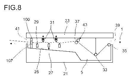
An apparatus according to the invention for impregnating fibers is illustrated
in a
sectional view in figure 7.
An apparatus in which the fibers 1 can be impregnated with matrix material
comprises a lower part 21 and a lid 23. The bath 5 having the matrix material
with
which the fibers 1 are to be soaked is located in the lower part 21. In the
movement direction of the fibers 1 the bath 5 is adjoined by a face 25 that is
inclined in the direction of the bath. Wipers 27, each having one wiping edge
29,
are disposed above the inclined face 25 on the lower part 21. The fibers 1 in
the
ongoing operation are guided across the wiping edge 29, and excess matrix
material is removed from the fibers 1. The wiped matrix material, on account
of
the positioning of the wipers 27 above the inclined face, flows back into the
bath 5.
Wipers 31 which are preferably adjustable for height are attached to the lid
23.
The wipers 31 on the lid 23 herein are preferably positioned such that said
wipers
31 mesh with the wipers 27 on the lower part 21. Furthermore, a deflection
unit 33
by way of which the fibers 1 in the case of a closed lid 23 are pushed into
the bath
5 is fitted to the lid 23. This is illustrated in figure 8. It can also be
derived
herefrom that the wipers 27 which are fastened to the lower part 21 mesh with
the
wipers 31 which are fitted to the lid 23. A slight zigzag profile is thus
embossed
onto the fibers 1.
In order for the fibers 1 before entering the bath 5 and after leaving the
bath 5 not
to be damaged on edges on the lower part, a first deflection unit 35 and a
second
deflection unit 37 are provided on the lower part 21 in the embodiment
illustrated
here. In the operation, the fibers 1, through a gap 39 between the lower part
21
and the lid 23, run into the apparatus for impregnating fibers and are guided
across the first deflection unit 35 on the lower part 21. The fibers 1
subsequently
run along the deflection unit 33 which is fitted to the lid 23 and by way of
which the
=
CA 03071298 2020-01-28
27
fibers 1 are immersed into the bath 5. The deflection unit 33 is adjoined by
the
second deflection unit 37 across which the fibers 1 are guided before the
latter are
fed to the wipers 27, 31 on which the excess matrix material is removed. The
soaked fibers then leave the apparatus through a second gap 41, and can be fed
to further processing, for example to the spindle 13 of a wet-wrapping method.
However, alternatively to components which are produced in the wet-wrapping
method, any other, for example also planar, components can be produced from
the impregnated fibers. To this end, it is possible, for example, for the
soaked
fibers to be cut to a desired length and to be molded in a suitable mold, so
as to
form the desired component. However, infeeding to a spindle 13 of a wet-
wrapping method is preferred.
On account of the immersion of the fibers 1 in the bath 5, large quantities of
matrix
material typically adhere to the fibrous structure 1 when the latter leaves
the bath
5. In order for a first excess of matrix material to be removed, it is
preferable for a
squeegee roller 43 which in the case of a closed lid 23 bears on the second
deflection unit 37 to be included, as is illustrated here. The soaked fibers
are then
guided through between the second deflection unit 37 and the squeegee roller
43.
The pressure at which the wipers 27, 31 act on the soaked fibers 1 can be set
by
setting the height of the wipers 31 that are fitted to the lid 23. On account
thereof,
it can be set in a targeted manner how much matrix material is to be contained
in
the soaked fibers 1. In the case of a comparatively high pressure which is
achieved in that the wipers 31 that are fitted to the lid 23 mesh more
intensively
with the wipers 27 on the lower part 21, more matrix material is squeezed from
the
soaked fibers 1, such that the latter overall contain less matrix material as
is the
case in a setting of the wipers 31 in such a manner that the latter mesh less
intensely with the wipers 27 on the lower part 21, the pressure acting on the
fibers
thus being lower.
The deflection unit 33 fitted to the lid 23, as well as the first deflection
unit 35 and
the second deflection unit 37 on the lower part 21, can in each case be
configured
in a mutually independent manner in the form of a bar or as a rotatable roll.
When
a deflection unit 33, 35, 37 is configured as a bar, the latter at least in
that region
in which contact with the fibers 1 takes place, preferably has only rounded
edges
and is particularly a round bar.
CA 03071298 2020-01-28
28
The wipers 27, 31 employed can assume any shape that is known to a person
skilled in the art for wipers. The wipers can also be aligned in a direction
that
deviates by 900 from that of the fibrous structure 1. In the case of the shape
and
the alignment of the wipers, attention has to be paid only that the soaked
fibers 1
are not consequentially damaged. The wipers herein can be designed and aligned
such as is already commonplace in the case of baths for soaking fibers.
In order for the fiber content by volume to be set in a precise manner, the
wipers
27 are adjoined by a unit for setting the fiber content by volume 100. The
fibers 1
are guided through the opening 107 of the unit for setting the fiber content
by
volume 100. The excess matrix material is wiped at the periphery of the
opening
107, drips onto the inclined face 25, and can then flow back into the bath 5.
By
contrast to the wipers 27 across which the fibers 1 are guided in a
preliminary
manner, on account of the defined cross-sectional area of the opening 107 only
so
much matrix material as is required for setting the desired fiber content by
volume
is removed. A substantially more precise setting is possible than in the case
of
wipers 27 that push onto the fibers 1 in an alternating manner from above and
from below.
Units for setting the fiber content by volume, in which the upper part 101
bears
directly on the lower part 103, or which alternatively can also be integrally
embodied, are illustrated in each of figures 7 to 11. The embodiment shown in
figures 1a to 2b can be used in the case of a design in two parts, for
example. The
plates 117, 119, or else the lamella aperture 121, can be used in these cases
in
order for the opening cross section to be set, for example.
Alternatively, the embodiment shown in figures 3a to 3c could also be
employed,
of course. This is illustrated hereunder in figure 12.
Alternative embodiments for the design of the deflection unit 33 that is
fitted to the
lid 23 are illustrated in figures 9 to 11. The remaining construction of the
apparatus for impregnating fibrous structures corresponds to that of the
embodiment illustrated in figures 7 and 8.
The deflection unit 33 in the case of the embodiment illustrated in figure 9
comprises a first deflection unit 45 that is fitted to the lid 23, and a
second
deflection unit 47 that is fitted to the lid 2. Here too, it is possible for
the first
CA 03071298 2020-01-28
29
deflection unit 45 that is fitted to the lid 23 and for the second deflection
unit that is
fitted to the lid 23 to be configured as a bar or a rotatable roll. The
position of the
first deflection unit 45 that is fitted to the lid 23, and of the second
deflection unit
47 that is fitted to the lid 23 is such that both deflection units 45, 47 in
the case of
a closed lid 23 are positioned between the first deflection unit 35 and the
second
deflection unit 37.
On account of the first deflection unit 45 that is fitted to the lid 23, and
of the
second deflection unit 47 that is fitted to the lid 23, the distance which is
traveled
by the fibers in the bath 5 can be extended, and the dwell time of the fibers
in the
bath 5 at the same speed can be increased, in relation to only one deflection
unit
as is illustrated in figures 7 and 8.
There can also be more deflection units that are embodied as a rotatable roll
or a
bar provided on the lid 23, but this is meaningful only when said additional
deflection units are in contact with the fibers 1 and the distance which the
fibers 1
travel in the bath 5 is further extended.
Alternatively to further deflection units on the lid 23, it is also possible
for an
additional deflection unit 49 in the bath 5 to be provided in order for the
distance in
the bath 5 to be extended and optionally for the impregnation to be improved.
As
is illustrated in figure 10, said additional deflection unit 49 is located
between the
first deflection unit 45 that is fitted to the lid 23, and the second
deflection unit 47
that is fitted to the lid 23. On account of the additional deflection unit 49
that is
located in the bath, the fibers are pushed against the deflection units 45, 47
that
are fitted to the lid and are simultaneously imparted pressure at the
additional
deflection unit 49. On account thereof, matrix material is pushed between the
fibers and any gas cushions that are optionally contained between the fibers
of the
fibers are forced out such that a uniform and above all also complete
impregnation
is achieved.
Apart from individual bars or rotatable rolls, such as are illustrated in
figures 7 to
10, the deflection unit 33 can also be configured in the form of a ram having
a
structured surface. This is illustrated in an exemplary manner in figure 11
for a
deflection unit having an undulated surface. The structure of the surface can
however also assume any other shape. Attention has only to be paid to be
fibers
CA 03071298 2020-01-28
not being damaged by the structure of the surface of the deflection unit 33
that is
configured as a ram.
=
An embodiment having an alternative design of the drip unit and having an
5 adjustable unit for setting the fiber content by volume is illustrated in
figure 12.
As opposed to the embodiments illustrated in figures 7 to 11, the drip unit
here is
not designed having mutually meshing wipers 27, 31.
10 In the case of the embodiment illustrated in figure 12, deflection units
51, for
example as a bar or a rotatable roll, are provided in the drip unit on the
lower part
21, and height-adjustable wipers 53 are provided on the lid 23. The fibers 1
are
guided through between the deflection units 51 and the wipers 53, wherein the
fibers 1 by way of the deflection units 51 are pushed against the wipers 53.
The
15 wipers 53 in terms of the height thereof can be adjusted such that the
latter can be
pushed against the deflection units 51 at an adjustable pressure. The quantity
of
matrix material in the soaked fibers can be set on account thereof. A further
deflection unit 55 is fitted to the lid between the wipers 53. It is ensured
by way of
said further deflection unit 55 that the fibers 1 are pushed against the
deflection
20 units 51 even when there is a gap between the deflection unit 51 and the
wiper
53.
As opposed to the preceding embodiments, it is shown here how a unit for
setting
the fiber content by volume 100 having an adjustable opening cross section
such
25 as is illustrated in figures 3a to 3c can be employed. In order to be
able to displace
the upper part 101 toward the lower part 103, the upper part 101 in the
embodiment illustrated here in the running direction of the fibers 1 lies
ahead of
the lower part 103 of the unit for setting the fiber content by volume 100.
Alternatively, it is of course also possible for the upper part 103 to be
disposed
30 such that the latter in the running direction of the fibers is
positioned behind the
lower part 103. A further possibility would also be for either the upper part
101 or
the lower part 103 to be designed having a slot that runs transversely to the
running direction of the fibers 1, and for the lower part 103 or the upper
part 101 to
be guided in a corresponding manner in this slot.
In order for the opening cross section to be set, the upper part 101 and/or
the
lower part 103 are/is fitted so as to be vertically displaceable. Additionally
or
CA 03071298 2020-01-28
31
alternatively, it is also possible for the upper part 101 and/or the lower
part 103 to
be fitted so as to be horizontally displaceable. To this end, the upper part
101
and/or the lower part 103 can be fitted onto a rail that runs transversely to
the
running direction of the fibers 1, for example, and be displaced on the rail
in order
for the opening cross section to be set.
In all embodiments it is possible for sealing elements to be provided in the
region
of the gaps 39, 41 through which the fibers are guided into the apparatus or
the
soaked fibers are guided out of the latter, respectively, in order for the
apparatus
to be sealed in respect of ambient air entering thereinto. This is
advantageous in
particular when a polymer or a polymer precursor compound, respectively, which
chemically reacts with a component of the air, for example with water that is
contained in the air, is used as a matrix material. Additionally, an inflow
and an
outflow for a flushing gas can be provided in order for the gas space above
the
bath to be flushed with the flushing gas.
In all embodiments illustrated here, the apparatus for impregnating fibers in
the
case of an embodiment having a unit for setting the fiber content by volume
100 in
two parts, in which the lower part 103 is fitted to the base of the apparatus
and the
upper part 103 is fitted to the lid 23 of the apparatus, permits a simple
start-up.
Independently of whether or not matrix material is already contained in the
bath 5,
it is possible in the case of an opened lid 23 for the fibers 1 to be placed
in a
simple manner. On account of the deflection units and wipers on the lid 23,
the
fibers are pushed against the respective deflection units and wipers on the
lower
part 21 and into the bath 5, thus assuming the envisaged path. No complicated
threading of the fibers or draining of the matrix material from the bath is
therefore
required for placing the fibers around a roller when using the apparatus
described
herein. Accordingly, the fibers can also be placed into the clearance 105 in
the
lower part 103, the opening 107 being closed by the respective positioning of
the
upper part 103 that is fastened to the lid 23 when the lid is being closed,
such that
the fibers 1 in the case of a closed lid lie in the opening 107 that is closed
all
around. The fibers can be removed again in a correspondingly simple manner
upon opening of the lid 23, even when the apparatus is switched off.
Additionally, by removing and replacing the lower part 21 it is possible in a
very
simple manner for either another matrix material to be supplied on demand, or
for
a lower part 21 to be removed on demand for cleaning or disposal and to be
CA 03071298 2020-01-28
32
replaced by a new lower part 21. On account thereof it is also possible in
particular for the apparatus to continue to operate even in the case of any
required
cleaning of the bath, in that a new lower part is easily employed while the
previous
lower part is being cleaned.
A device for impregnating fibers, in which the fibers are fed as bundles, are
singularized for impregnation, and are subsequently gathered again, is
illustrated
in figures 13 and 14, wherein figure 13 shows the device in the plan view, and
figure 14 is a sectional illustration.
In the embodiment illustrated in figures 13 and 14 the fibers 1 are fed
through an
opening 59 in order for the fibers to be fed into the bath 1 with matrix
material. The
opening 59 for feeding the fibers 1 in the embodiment illustrated here is
designed
so as to be conical in order for the threading of the fibers 1 to be
facilitated. The
cross-sectional face of the opening 59 at the tightest cross-section thereof
preferably corresponds to the cross-sectional face of the infed fibers 1.
Upon entering the bath 5, the infed fibers 1, which are fed either as a fiber
bundle
or as a bundle from a plurality of rovings, are split. Splitting herein is
performed
either into individual fibers or into bundles having a lower number of fibers,
or in
the case of an infed bundle from rovings, into individual rovings, so as to
guarantee improved soaking of the fibers 1 with the matrix material that is
contained in the bath 5. In order to be able to split the fibers 1, deflection
elements
57 about which the infed individual fibers, groups of a lower number of
fibers, or
individual rovings are guided, are positioned in the bath 5. The number of the
deflection elements 57 herein depends on the number of individual fibers,
groups
of a lower number of fibers, or individual rovings, which are guided through
the
bath 5. The individual fibers, groups from a lower number of fibers, or
individual
rovings, are gathered again behind the deflection elements 57 and fed to the
unit
for setting the fiber content by volume 100. The installation for setting the
fiber
content by volume 100 in the embodiment illustrated in figures 13 and 14 is
likewise configured as an opening 107 in the wall of the bath 5. The fibers
are
guided through the opening 107 which for improved threading of the fibers is
likewise configured with a decreasing cross-sectional face.
Besides the variant illustrated here, in which the tightest cross-section is
on the
outlet side of the fibers, it is also possible for the opening 59 for feeding
the fibers,
CA 03071298 2020-01-28
33
and the opening 107 of the unit for setting the fiber content by volume 100,
to be
designed such that the cross-sectional face initially decreases in the running
direction of the fibers in operation, until the minimal cross-sectional face
is
reached, and subsequently increases again.
The minimal cross-sectional face of the opening 59 for feeding the fibers
preferably corresponds to the cross-sectional face of the fibers that are fed
through the opening 59. On account thereof, sealing in relation to the matrix
material by way of which the fibers are soaked and which is contained in the
bath
5 can be achieved to a large extent on account thereof.
On account of the design of the opening 107 of the unit for setting the fiber
content by volume 100, only so much matrix material as is required in order
for the
fibers to be soaked exits the bath also here. The soaked fibers moreover act
as a
seal here, by way of which an outflow of the matrix material from the bath 5
is
prevented.
In order for the fibers 1 to be as far as possible completely soaked and for
gas, in
particular air, that is still contained in the fibers to be expelled, wipers
53 are
additionally provided in the bath 5. The wipers herein, as is illustrated
here, are
preferably disposed above and below the fibers 1, wherein the wiping edges are
aligned such that the wipers 53.1, which act on the fibers 1 from above, press
the
fibers onto the wipers 53.2, which act on the fibers 1 from below, and in a
corresponding manner the wipers 53.2 that act on the fibers 1 from below push
the fibers 1 against the wipers 53.1 that act on the fibers 1 from above. The
pressure that acts on the fibers 1 and thus the effectiveness of the wipers 53
for
expelling the gas can be set by the height by way of which the wipers 53
engage
in one another.
Since the opening 59 for feeding the fibers 1 and the unit for setting the
fiber
content by volume 100 illustrated in the embodiment illustrated in figures 13
and
14 lie below the liquid level of the matrix material, the fibers for the
operation are
placed first, and the matrix material is filled into the bath 5 only once the
fibers 1
have been placed therein. Facilitated placing of the fibers 1 can be achieved,
for
example, in that the wipers 53.1 which act on the fibers 1 from above are
inserted
only once the fibers have been placed. To this end it is possible, for
example, for
the wiper 53.1 to be guided in a groove in the wall of the bath 5, or for the
wipers
CA 03071298 2020-01-28
34
53.1 that act on the fibers 1 from above to be placed onto the wall of the
bath 5 by
way of a support or a lid that closes the bath. The wipers 53.2 that act on
the
fibers from below can be fastened to the base of the bath 5, for example.
In order for a good result to be achieved by the wipers 53, at least three
wipers
are provided, wherein the wipers can in each case act on the fibers in an
alternating manner from above and from below. In the case of three wipers, two
wipers 53.2 can act on the fibers from below and one wiper 53.1 can act from
above, as is illustrated here for example. However, reversed arrangement is
alternatively also possible, in which two wipers act on the fibers from above,
and
one wiper acts on the fibers from below. The position of the opening 59 for
feeding
the fibers 1 herein is preferably such that the opening 59, in the case of a
wiper
that acts on the fibers from above being the first wiper behind the opening 59
for
feeding the fibers, lies above the wiping edge of the first wiper, and in the
case of
a wiper acting on the fibers from below being the first wiper behind the
opening 59
for feeding the fibers, lies below the wiping edge of the first wiper.
Accordingly, the
opening of the unit for setting the fiber content by volume, in the case of a
wiper
53.1 which acts on the fibers 1 from above and which in the running direction
of
the fibers lies as the last wiper ahead of the opening of the unit for setting
the fiber
content by volume, lies above the wiping edge, and in the case of a wiper 53.2
that acts from below lies below the wiping edge. The fibers, on account of the
corresponding positioning of the opening 59 for feeding the fibers, and of the
opening of the unit for setting the fiber content by volume 100, are also
pressed
against the wiping edge of the first and of the last wiper 53.
An embodiment of the device for impregnating fibers, which in terms of the
construction thereof largely corresponds to that shown in figures 13 and 14,
but as
opposed to the latter is closable by way of a lid, is shown in figures 15 and
16.
Fibers 1, also in the case of the embodiment illustrated in figures 15 and 16,
are
guided into the bath 5 through an opening 59 for feeding the fibers. The
wipers 53
which act on the fibers from above and from below are located in the bath 5.
The
wipers 53.2 which act on the fibers from below, are fastened to the lower part
21,
and the wipers 53.1 which act on the fibers from above are fastened to the lid
23.
In order for the placing of the fibers to facilitated, the lower part 21 and
the lid 23
are designed such that the opening 59 through which the fibers are fed, and
the
CA 03071298 2020-01-28
opening which forms the unit for setting the fiber content by volume 100, are
designed such that in each case one part of the openings, preferably more than
half of the opening, is configured in the lower part 21, and the remaining
part of
the opening is configured in the lid 23. This permits the fibers to be placed
in a
5 simple manner from above into the opening 59 for feeding the fibers, and
into the
opening 107 that forms the unit for setting the fiber content by volume 100.
Once
the fibers 1 have been placed, and the fibers have been split into individual
fibers,
groups of fewer fibers, or in the case of a bundle of rovings into individual
rovings,
which are guided about the deflection units 57, the lid 23 is placed on top as
is
10 illustrated in figure 16. The opening 59 through which the fibers are
fed, and the
opening 107 of the unit for setting the fiber content by volume 100 are closed
by
way of the lid. The wipers 53.1 that are fastened to the lid 23 are
simultaneously
pressed onto the fibers such that the fibers 1 in turn are pressed onto the
wipers
53.2 that are fastened on the base. On account thereof, the wipers 53.2 that
are
15 fastened on the base act on the fibers from below, and the wipers 53.1
that are
fastened to the lid act from above.
After the lid 53 is closed, the matrix material is filled into the bath 5 by
way of a
suitable infeed opening which is preferably closable. The space that is formed
20 between the lower part 21 and the lid 23 herein is preferably completely
filled with
the matrix material. The infeed opening for the matrix material herein is
preferably
located in the lid such that the matrix material can be filled from above into
the
interior space which is enclosed by the lower part 21 and the lid 23. A
sealing
element for sealing the bath is incorporated between the lower part 21 and the
lid
25 .. 23. Any arbitrary seal known to a person skilled in the art is suitable
to this end. It
is thus possible, for example, for a groove to be configured in the lower part
21 or
in the lid 23, and for a seal, for example an 0-ring, to be placed in the
groove.
The position of the opening 59 for feeding the fibers 1, and of the opening
107 of
30 the unit for setting the fiber content by volume 100 enable the entire
device for
impregnating fibers to be positioned in an arbitrary manner, since the fibers
on
account of the filling of the entire interior space with the matrix material
are
sufficiently soaked even when the device is rotated, for example, by an
arbitrary
angle about the longitudinal axis or the transverse axis. This has the
advantage
35 that the device for impregnating the fibers can be aligned in a suitable
manner
when the fibers in continuous or discontinuous winding processes are fed to
the
winding core from different directions. The individual devices for
impregnating
CA 03071298 2020-01-28
36
fibers herein are preferably aligned such that the fiber after exiting the
unit for
setting the fiber content by volume does not have to be deflected any more
between the device for impregnating the fibers and the winding core. It is
ensured
in this way that no matrix material is squeezed out of the fiber by a
deflection
device, for example a roller, but the fibers are wound onto the winding core
having
the fiber content by volume by way of which said fibers exit the device for
impregnation.
A device for impregnating fiber tapes is illustrated in the plan view and in
this side
view in figure 17 and 18. The functional mode of the device herein largely
corresponds to the functional mode of the devices as are illustrated in
figures 13
to 16.
The device illustrated in figure 17 and 18 also preferably has a lower part 21
and a
lid 23, like the device illustrated in figures 15 and 16, wherein the openings
through which the fiber tapes 61 are guided are configured in the lower part
21
and are open on the upper side, and are closed by way of the lid 23 once the
fiber
tapes 61 have been placed therein. Since the fiber tapes are flat, the
openings in
the lower part in this case preferably have a rectangular cross-section,
wherein
the height of the opening 59 for feeding the fiber tapes corresponds to the
width of
the fiber tapes 61, and the width of the opening 59 for feeding the fiber
tapes
corresponds to the thickness of the infed stack from a plurality of fiber
tapes 61.
The opening 107 of the unit for setting the fiber content by volume is
likewise
preferably rectangular, wherein the cross-sectional face is calculated here so
as to
depend on the desired fiber content by volume, as has been described above.
As opposed to individual fibers or individual rovings, or else groups having a
lower
number of fibers, it is necessary in the case of fiber tapes 61 by virtue of
the
geometry that both the deflection elements as well as the wipers act on the
wide
face of the fiber tapes 61. Therefore, as opposed to the embodiments
illustrated in
figures 13 to 16, no deflection elements and wipers that in relation to the
deflection units 57 are rotated by 90 are used for the impregnation of fiber
tapes,
but at least two, preferably at least three, deflection units 57 are used for
each
fiber tape 61, said deflection units 57 being positioned such that a fiber
tape 61
that is guided by way of the deflection units 57 is in each case pressed by
one
deflection element 57 against the neighboring deflection element 57. Zig-zag
guiding of the fiber tapes 61 in the bath 5 results on account thereof, and
the
CA 03071298 2020-01-28
37
deflection elements 57 simultaneously act also as wipers. Of course, such
guiding
is alternatively also possible for individual fibers, groups from a low number
of
fibers, or individual rovings, wherein by virtue of the required space and of
the
lower complexity in terms of assembly and of the lower complexity for placing
the
fibers, it is preferable for deflection elements 57 and wipers that in
relation to said
deflection elements 57 are rotated by 900 to be provided.
A further embodiment of a device for impregnating fibers is illustrated in
figures 19
and 20. Figure 19 shows the device in the ongoing operation during
impregnating,
and figure 20 shows the device prior to the fibers being incorporated into the
bath.
As opposed to the devices illustrated in figures 13 to 18, in the case of the
device
illustrated in figures 19 and 20 the fibers 1 are not guided into the bath 5
through
an opening 59 for feeding the fibers 1, said opening 59 in operation being
located
below the liquid level of the matrix material, but are guided by way of a
deflection
roller 63 from above into the bath 5. In order for the fibers 1 after the
deflection
roller 63 to be guided into the bath, a wiper 53.1 is first provided in the
running
direction 55 of the fibers 1, said wiper 53.1 acting on the fibers from above.
The
fibers 1, after passing the deflection roller 63, are pushed into the bath by
way of
the wiper 53.1 which acts on the fibers from above. The first wiper 53.1 which
acts
on the fibers 1 from above is adjoined by at least one wiper 53.2 which acts
on the
fibers 1 from below, and by a further wiper 53.1 which acts on the fibers from
above. Even further wipers can also be provided, wherein the last wiper 53 in
the
running direction of the fibers 1 is a wiper 53.1 that acts on the fibers from
above.
The fibers after the last wiper 53.1 are guided through the installation for
setting
the fiber content by volume 100, said installation by way of one side being
submerged in the matrix material and by way of the other end, through which
the
fibers exit the installation for setting the fiber content by volume 100,
lying outside
the matrix material. Subsequent to the installation for setting the fiber
content by
volume 100, the soaked fibers are guided by way of a further deflection roller
65.
Instead of the deflection rollers 63, 65 which are illustrated in figures 19
and 20, it
is also possible for other arbitrary suitable deflection roller is to be used,
such as
are described above as deflection units 35, 37 in figures 7 to 11.
In order for the fiber content by volume of the impregnated fibers to be set,
the
unit for setting the fiber content by volume 100 in the embodiment illustrated
here
CA 03071298 2020-01-28
38
has a nozzle 123 and a duct 125. The nozzle has the minimal cross-sectional
face
which is dimensioned such that the desired fiber content by volume is
achieved.
The nozzle 123 is adjoined by the duct 125, wherein the duct 125 has a cross-
sectional face which is so large that the soaked fibers which are guided
through
the duct 125 do not contact the walls of the duct. In order to prevent that
air
bubbles or gas bubbles are incorporated into the fibers when impregnating, the
unit for setting the fiber content by volume 100 by way of the nozzle 123
submerges into the matrix material in the bath 5. The soaked fibers, after
passing
the nozzle, can be guided out of the matrix material in the bath 5 through the
duct
125 that adjoins the nozzle, without said fibers once again coming into
contact
with the matrix material, such that the fiber content by volume after passing
the
nozzle is no longer changed. To this end, the duct 125 is connected to the
nozzle
in a liquid-tight manner such that no matrix material can make its way out of
the
bath 5 into the duct 125. The end of the duct 125 through which the fibers
exit, in
operation is located outside the matrix material.
In order for the fibers to be able to be placed into the device for
impregnating
fibers in a simple manner, the wipers 53.1 that act on the fibers from above,
and
the unit for setting the fiber content by volume 100, are preferably fitted so
as to
be retrievable from the bath 5. This is schematically illustrated in figure
20, in
which the device is shown prior to the fibers 1 being placed therein. The
fibers 1 to
be impregnated are first located outside the matrix material, above the bath
5. The
fibers 1 are first placed into the unit for setting the fiber content by
volume 100.
The wipers 53.1 which act on the fibers 1 from above are likewise still
located
outside the bath 5. Once the fibers 1 have been placed into the unit for
setting the
fiber content by volume 100, said fibers 1 by way of the wipers 53.1 that act
on the
fibers 1 from above are pressed downward. To this end, the wipers 53.1 can be
guided, for example, in the groove in the container that contains the bath 5,
or
alternatively can be fitted on the upper edge of the container that contains
the
bath 5 by way of the support. In order for the unit for setting the fiber
content by
volume 5 to be positioned such that said unit for setting the fiber content by
volume by way of one side, preferably the side that has the nozzle 123, can
submerge into the matrix material that is contained in the bath, and the other
end
of the unit for setting the fiber content by volume 100, from which the
impregnated
fibers can exit again, is outside the matrix material, the unit for setting
the fiber
content by volume is preferably fitted so as to be movable on a suitable
mounting
CA 03071298 2020-01-28
39
by way of which the unit for setting the fiber content by volume 100 can be
fitted to
the container that contains the bath 5.
The device shown in figures 19 and 20 has the advantage that the fibers, as is
the
case also in the devices shown in figures 7 to 12, can be placed in a simple
manner without the matrix material having to be removed from the bath 5.
A variant of how the wipers 53.1 that act on the fibers from above, and the
unit for
setting the fiber content by volume 100, can be fitted is illustrated in
figures 21 and
22. Here, the wipers 53.1 and the unit for setting the fiber content by volume
100
are fastened to a lid 23 which is placed onto the lower part 21 that contains
the
bath 5. This embodiment in figure 1 is shown with a partially opened lid, and
in
figure 22 is shown with a closed lid.
The unit for setting the fiber content by volume herein by way of a first arm
127 is
fitted to the lid 21, and by way of a second arm 129 is fitted to the lower
part 21.
The first arm 127 and the second 129 are in each case fastened to the duct 125
of
the unit for setting the fiber content by volume 100 so as to be rotatable
about an
axis that runs perpendicularly to the fibers 1. On account thereof, the unit
for
setting the fiber content by volume 100, when closing the lid 23, is moved to
the
desired position. The fibers are pressed into the matrix material in the bath
5 by
way of the wipers 53.1 which are fastened to the lid 21 and act on the fibers
1
from above, wherein the fibers in the case of a closed lid by way of the
wipers
53.1 that act on the fibers 1 from above are pressed against the wipers 53.2
that
act on the fibers from below. The wiper that acts on the fibers 1 from below
herein
is fastened to the lower part 21.
In the case of the embodiments shown in figures 19 to 22 the fibers can be fed
as
a fiber bundle or as a bundle from a plurality of individual rovings, and in
the bath
5 can be split into individual fibers, units from a lower number of fibers, or
individual rovings, in order for the fibers to be able to be completely
soaked,
wherein the fibers or rovings after soaking are gathered again, before said
fibers
or rovings are guided through the unit for setting the fiber content by
volume.
Splitting herein, as in the embodiments already described in the context of
figures
13 to 16, can be performed by using deflection units 57 about which the
individual
fibers, units from a lower number of fibers, or rovings are guided.
CA 03071298 2020-01-28
In the case of the embodiments shown in figures 19 to 22 it is alternatively
also
possible for the fibers to be fed so as to already be split into individual
fibers, units
from a low number of fibers, or individual rovings, to be gathered prior to
entering
the unit for setting the fiber content by volume 100, and thus to be retrieved
as a
5 bundle from the device for impregnating fibers. Such an embodiment is
illustrated
in exemplary manner in the plan view in figure 23.
In particular when the impregnated fibers are used for producing wound
components, for example pipes, it is necessary for the fibers after
impregnation to
10 be split again into individual fibers, groups of few fibers, or
individual rovings,
those then being fed to a winding mandrel about which the impregnated fibers
are
used for producing the wound component. This splitting of the fibers after the
impregnation is likewise illustrated in exemplary manner in figure 23, can
however
also be carried out thus for all other embodiments shown here.
After exiting the unit for setting the fiber content by volume 100, the fibers
1 are
first guided through a guide 73 and subsequently fed to a comb 67. The
individual
fibers, units of a low number of fibers, or individual rovings, in the comb 67
are in
each case guided around one prong 69 of the comb 67 such that said fibers or
rovings can subsequently be fed lying beside one another in parallel to the
winding mandrel 71 or the winding core about which the fibers are then wound
lying beside one another in parallel. In order for the component to be
produced,
either the winding mandrel 71 or the winding core is moved in a reciprocating
manner along the axis 75 thereof, or the comb 67 is moved in a reciprocating
manner parallel with the axis 75 of the winding mandrel 71 or of the comb, so
as
to produce a component having a plurality of fiber tiers which lie on top of
one
another so as to be rotated in relation to one another at an angle. The angle
at
which the fibers of the individual tiers are rotated in relation to one
another herein
is set by way of the rotating speed of the winding mandrel 71 or of the
winding
core, and by way of the reciprocating movement of the winding mandrel 71 or of
the winding core, or by way of the reciprocating movement of the comb 67,
respectively.
In order for the fibers to be able to be placed in a simple manner in the case
of the
device as is illustrated in a plurality of embodiments in figures 19 to 23, it
is
particularly advantageous for the unit for setting the fiber content by volume
100 to
be embodied in two parts. This is shown in an exemplary manner in figures 24
CA 03071298 2020-01-28
41
and 25. To this end, the unit for setting the fiber content by volume has a
lower
part 133 and a lid 131. The nozzle 123 is configured in the lower part 133 and
is
positioned such that said nozzle 123 in the case of an opened lid 131 is
opened
toward the top. The fibers in the case an opened lid 131 can thus be placed
into
.. the lower part 133 in a simple manner, the lid being closed once the fibers
1 have
been placed.
In order to prevent that the fibers in the case of a method in which the
fibers after
impregnating are to be split up again form knots and an unintentional stoppage
of
the device thus arises, it is advantageous in the case of all embodiments for
the
fibers to first be placed in a simple manner from above before the fibers 1
are
pressed into the matrix material in the bath 5. An entanglement of the fibers
herein
is prevented in that fibers are first guided through the intermediate spaces
between the prongs 69 of the comb 67 and by way of the comb 7 ahead of the
device for impregnating the fibers. Independently of whether the fibers are
fed as
individual fibers, as a group of few fibers, or as individual rovings, such as
is
illustrated in figure 23, or as a bundle, through an opening 59 for feeding
fibers, or
else as a bundle by way of a deflection unit 35, 63, the fibers are next
placed
around the deflection units 57 in the bath 5. The fibers subsequently are
gathered
between the deflection units 57 in the bath 5 and the comb 67 and placed into
the
unit for setting the fiber content by volume 100, the latter to this end being
embodied in preferably two parts, having an upper part 101 and a lower part
103,
or a lower part 133 and a lid 131 such that the fibers can be placed in the
lower
part 103, 133 and the upper part 101 or the lid 131 is subsequently placed
thereon. When the guide 73 which is used in particular in the embodiment of
the
unit for setting the fiber content by volume having the nozzle 123 and the
duct
125, is provided in order to prevent that the fibers contact the wall of the
duct 125,
on account of which matrix material can be wiped off, said guide 73 is
likewise
preferably inserted only once the fibers have been placed into the comb 67 and
the fibers 1 have been placed about the deflection units 57, to which end the
guide 73 is preferably likewise embodied in two parts, such that said guide 73
can
be placed around the fibers 1 in an open state and can subsequently be closed.
In
the case of an embodiment in two parts, besides a separate upper part and a
lower part, or a separate lower part and a lid, it is always also possible for
the
lower part and the upper part, or the lower part and the lid, to be connected
by a
hinge such that the lid for closing is rotated about the axis of the hinge.
CA 03071298 2020-01-28
42
When the fibers are guided through an opening 59 for feeding the fibers, the
fibers
after having been placed into the unit for setting the fiber content by volume
are
gathered between the deflection units 57 in the bath 5 and the comb 7 and
placed
into the opening 59 for feeding the fibers 1, said opening 59 after the fibers
have
been placed completely therein, being closed, for example by closing the lid
23.
Of course, it is also possible here for the fibers to be first placed into the
opening
59 for feeding the fibers, and thereafter into the unit for setting the fiber
content by
volume 100.
Depending on the number of fibers to be impregnated and on the number of
fibers
which are to be guided through the unit for setting the fiber content by
volume
100, besides the embodiments having only one unit for setting the fiber
content by
volume 100 illustrated here, an arbitrary number of further units for setting
the
fiber content by volume can also be used. It is possible herein for a
plurality of
units for setting the fiber content by volume 100 to be used on a bath 5, or
alternatively also for a plurality of devices for impregnating fibers 1,
having in each
case one unit for setting the fiber content by volume, to be used in parallel.
CA 03071298 2020-01-28
43
List of reference signs
1 Fibers
3 Reserve
5 Bath
7 Comb
9 Squeegee roller pair
11 Guide ring
13 Spindle
15 Component
21 Lower part
23 Lid
25 Inclined face
27 Wiper
29 Wiping edge
31 Wiper
33 Deflection unit
35 First deflection unit on lower part 21
37 Second deflection unit on lower part 21
39 Gap
41 Second gap
43 Squeegee roller
45 First deflection unit fitted to lid 23
47 Second deflection unit fitted to lid 23
49 Additional deflection unit in bath 5
51 Deflection unit
53 Wiper
53.1 Wiper acting on the fibers from above
53.2 Wiper acting on the fibers from below
55 Running direction
57 Deflection unit
59 Opening for feeding the fibers 1
61 Fiber tape
63 Deflection roller
65 Deflection roller
67 Comb
69 Prongs
CA 03071298 2020-01-28
44
71 Winding mandrel
73 Guide
75 Axis of the winding mandrel
100 Unit for setting the fiber content by volume
101 Upper part
103 Lower part
105 Clearance
107 Opening
109 Periphery of opening
.. 111 Minimum opening cross section
113 Lateral face
115 Semicircular base
117 Plate
119 Plate
121 Lamella aperture
123 Nozzle
125 Duct
127 First arm
129 Second arm
131 Lid
133 Lower part