Note: Descriptions are shown in the official language in which they were submitted.
CA 03071400 2020-01-28
WO 2019/028154 PCT/US2018/044833
MULTI-CHAMBER BAG
BACKGROUND
Technical Field
[0001] This disclosure relates to a flexible container, such as a storage bag
for food
products and the like. More particularly, the present invention relates to a
bag having a
plurality of chambers separated by a releasable seal and vented for microwave
cooking of
sealed food products.
Related Art
[0002] Some storage bags can have a single compartment or chamber in which to
store
edible goods. Such storage bags can be used for transport and display of
various food
goods in, for example, a grocery store. However, such goods are only stored in
such storage
bags. In order to prepare or heat the subject food goods, they must be removed
from the
storage bags and prepared in a different container before they can be
consumed.
SUMMARY
[0003] Aspects of the present application include a storage bag including a
film sheet.
The film sheet defines a first chamber, a second chamber located adjacent the
first
chamber; and a releasable seal preventing fluid communication between the
first chamber
and the second chamber. The releasable seal may be configured to release or
release
when an internal temperature within either the first chamber or the second
chamber
exceeds a temperature threshold or an internal pressure within either the
first chamber or
the second chamber exceeds a pressure threshold or upon a desired combination
of
temperature and pressure being exceeded.
[0004] An aspect of the disclosure provides a multi-chamber storage bag formed
of a film
sheet. The storage bag can have a first chamber. The storage bag can have a
second
chamber located adjacent the first chamber. The storage bag can have a
releasable seal
joining the first chamber and the second. The
releasable seal can prevent fluid
communication between the first chamber and the second chamber. The releasable
seal
can release in response to an internal temperature within the first chamber
exceeds a
temperature threshold. The releasable seal can release in response to an
internal
temperature within the second chamber exceeds the temperature threshold. The
releasable seal can release in response to a temperature of the releasable
seal exceeding
a threshold. The releasable seal can release in response to an internal
pressure within the
1
CA 03071400 2020-01-28
WO 2019/028154 PCT/US2018/044833
first chamber exceeds a pressure threshold. The releasable seal can release in
response to
an internal pressure within the second chamber exceeds the pressure threshold.
[0005] Another aspect of the disclosure provides a storage bag. The storage
bag can
have an upper chamber formed from a first plurality of panels of a film sheet,
and
configured to contain a first edible food. The storage bag can have a lower
chamber
disposed adjacent the upper chamber and formed from a second plurality of
panels of the
film sheet. The second plurality of panels can have a plurality of apertures,
the lower
chamber being configured to contain a second edible food. The storage bag can
have a
releasable seal disposed between the upper chamber and the lower chamber. The
releasable seal can prevent fluid communication between the upper chamber and
the lower
chamber when ambient pressure within the lower chamber is below a threshold.
The
releasable seal can release when a pressure within the lower chamber rises
above a
threshold.
[0006] Other features and advantages will be apparent to one of ordinary skill
in the art
with a review of the following detailed description.
BRIEF DESCRIPTION OF THE DRAWINGS
[0007] The details of embodiments of the present disclosure, both as to their
structure
and operation, can be gleaned in part by study of the accompanying drawings,
in which like
reference numerals refer to like parts, and in which:
[0008] FIG. 1 is a graphical depiction of a front view of a storage bag
according to an
example implementation of the disclosed dual chamber bag;
[0009] FIG. 2 is a graphical depiction of a pair of sheets 125, 130 that may
form the
upper chamber 105 of the storage bag 100 of FIG. 1;
[0010] FIG. 3 is a graphical depiction of a pair of sheets 160, 165 that may
form the
releasable seal 115 of the storage bag 100 of FIG. 1;
[0011] FIG. 4 is a cross section of an embodiment of the closure mechanism
taken along
the line 4 - 4 of FIG. 1;
[0012] FIG. 5 is a cross section of another embodiment of the closure
mechanism taken
along the line 4 - 4 of FIG. 1;
[0013] FIG. 6 is a cross section of another embodiment of the closure
mechanism taken
along the line 4 - 4 of FIG. 1;
[0014] FIG. 7 is a graphical representation of sheet 135 that forms the lower
chamber
110 of the storage bag 100 of FIG. 1;
[0015] FIG. 8 is a graphical depiction of the sheet 125 of FIG. 1;
[0016] FIG. 9 is a graphical depiction of the sheet 130 of FIG. 1;
2
CA 03071400 2020-01-28
WO 2019/028154 PCT/US2018/044833
[0017] FIG. 10 is a graphical representation of another embodiment of the bag
of FIG. 1;
[0018] FIG. 11 is a perspective view of a bag 100 of FIG. 1; and
[0019] FIG. 12 is another perspective view of the bag of FIG. 1.
DETAILED DESCRIPTION
[0020] Patent Body Reference throughout this specification to "one embodiment"
or "an
embodiment" means that a particular feature, structure, or characteristic
described in
connection with the embodiment is included in at least one embodiment. Thus,
appearances of the phrases "in one embodiment" or "in an embodiment" in
various places
throughout this specification are not necessarily all referring to the same
embodiment.
Furthermore, the particular features, structures, or characteristics may be
combined in any
suitable manner in one or more embodiments.
[0021] The following detailed description provides further details of the
figures and
example implementations of the present application. Reference numerals and
descriptions
of redundant elements between figures are omitted for clarity. Terms used
throughout the
description are provided as examples and are not intended to be limiting. For
example, the
use of the term "automatic" may involve fully automatic or semi-automatic
implementations
involving user or operator control over certain aspects of the implementation,
depending on
the desired implementation of one of ordinary skill in the art practicing
implementations of
the present application.
[0022] FIG. 1 is a graphical depiction of a front view of an embodiment of a
storage bag
100. The storage bag 100 can have a first chamber 105 and a second chamber
110.
When stood upright, the second chamber 110 can be located vertically below the
first
chamber 105. Thus, as described herein, the first chamber 105 may be referred
to as the
upper chamber 105 and the second chamber 110 may be referred to as the lower
chamber
110.
[0023] A releasable seal 115 can be located between the upper chamber 105 and
the
lower chamber 110. The releasable seal 115 may be configured to provide a
fluid tight
seal between the upper chamber 105 and the lower chamber 110 such that liquid
or gas
may not pass between the upper chamber 105 and the lower chamber 110 while the
releasable seal 115 is closed. The upper chamber 105 and the lower chamber 110
can be
formed from a single film sheet or from multiple segments of film sheets that
are joined
together as a single film sheet. These aspects are described below, in
connection with FIG.
2 through FIG. 10. The terms "upper" and "lower" are not limiting on the scope
of the
disclosure.
3
CA 03071400 2020-01-28
WO 2019/028154 PCT/US2018/044833
[0024] In some example implementations, the releasable seal 115 may include a
closure
mechanism 145 formed by closure elements 150, 155 located on opposing seal
member
sheets 160, 165. In some other embodiments, the closure elements 150, 155 can
be
opposing or complementary sides of a seal to provide the fluid tight seal
between the upper
chamber 105 and the lower chamber 110. For example, the closure elements 150,
155
can form a complementary zipper-like attachment between each other, such as a
press-
and-lock zipper-style seal (see FIG 4). As another example, the closure
elements 150, 155
can be two opposing sides of the storage bag which are adhered to each other,
for example
using an adhesive (see FIG. 5). As another example, the closure elements 150,
155 can be
opposing hook-and-loop style fasteners (see FIG. 6).
[0025] In some example implementations, the releasable seal 115 provided by
the
closure elements 150, 155 may be configured to release in response to an
internal
temperature and/or pressure within the upper chamber 105 and lower chamber 110
exceeding a threshold. An exemplary benefit of various embodiments of the
releasable seal
is the fluid tight seal is maintained until the edible contents of the lower
chamber 110 are
sufficiently cooked and the (steam) pressure within the lower chamber 110 has
built to the
point at which the releasable seal 115 is broken, providing fluid
communication between
the upper chamber 105 and the lower chamber 110. This feature is described in
further
detail in connection with FIG. 3 through FIG. 6, below. It is noted that the
releasable seal
115 and the closure mechanism 145 of FIG. 1 resembles a zipper style seal,
however the
disclosure and the closure mechanism 145 are not so limited. Other
example
implementations of the releasable seal 115 are disclosed, for example, in
connection with
FIG. 3, FIG. 4, FIG. 5, and FIG. 6, below.
[0026] The storage bag 100 can include one or more ventilation openings 120.
The
ventilation openings 120 can be apertures or perforations providing fluid
communication
between an exterior atmosphere 10 surrounding the storage bag 100 and the
lower
chamber 110 to control pressure within the lower chamber 110. The ventilation
openings
120 can ensure the releasable seal 115 does not release (e.g., separate,
rupture, partially
separate or partially rupture) prematurely and that the chamber does not
release
somewhere other than at the releasable seal. The number and size of the
ventilation
openings 120 may be selected such that during heating of the storage bag 100,
the
pressure within the lower chamber 110 increases at a particular rate such that
edible
goods in the upper chamber 105 and the lower chamber 110 are cooked or heated
to a
desired level prior to the releasable seal 115 rupturing. The rate of pressure
change within
the lower chamber 110 may be affected by the water/steam content of the edible
goods in
the upper chamber 105 and the lower chamber 110. For example, if the edible
goods are
potatoes, 8 ventilation openings having an average diameter of 1-1.5 mm may
provide
4
CA 03071400 2020-01-28
WO 2019/028154 PCT/US2018/044833
sufficient ventilation to control release of the releasable seal 115 until the
potatoes are
sufficiently cooked (approximately 6 minutes into heating). The number of the
openings
can vary, as can their size, in relation to the amount of edible goods.
Alternatively, a one
way or two way gas releasing valve may be used to control and release the
pressure.
[0027] As illustrated in FIG. 2 through FIG. 10, the storage bag 100 may be
formed from
a plurality of sheets 125, 130, 135, 160, 165 of film material joined together
by
overlapping seals 140, 170, 175, 180 (represented by dotted patterns). The
seals 140,
170, 175, 180 may be structured to avoid release even during heating of the
bag, but may
allow tearing or opening by a user after heating has been completed. In one
example, the
seals are formed by heat and pressure applied to overlapping portions of the
sheets.
[0028] FIG. 2 is a graphical depiction of a pair of sheets 125, 130 that may
form the
upper chamber 105 of the storage bag 100 of FIG. 1. In some example
implementations,
each sheet 125, 130 may be formed from a composite film material formed from a
combination of 12 microns of polyester film and 100 microns of polypropylene.
However,
example implementations are not limited to these materials and other food
safe/microwave
safe films (such as orientated polypropylene film, polyamide film, etc.) may
be apparent to a
person of ordinary skill in the art. Additionally, a two-layer film may
provide sufficient
mechanical strength maintain to steam pressure during heating. However, other
film
constructions may be apparent to a person of ordinary skill in the art.
[0029] As illustrated, the sheet 125 includes vertical peripheral regions 205,
a lower
peripheral region 215 and an upper peripheral region 235 illustrated as the
areas outside
of the broken line box 220 of FIG. 2. Similarly, the sheet 130 includes
vertical peripheral
regions 210, a lower peripheral region 230 and a upper peripheral region 240
illustrated as
the areas outside of the broken line box 225 of FIG. 2. The vertical
peripheral regions 205
of sheet 125 may be bonded to the vertical regions 210 of the sheet 130 to
form part of
the vertical seal 195 (represented by a dotted pattern) along edges of the
upper chamber
105 (FIG. 1). Further, the upper peripheral regions 235, 240 may be bonded
together to
form the upper seal 140 (represented by a dotted pattern) along the top edge
of the upper
chamber 105 (FIG. 1). Bonding may be achieved by heat sealing, adhesive
application or
any other bonding process that might be apparent to a person of ordinary skill
in the art.
[0030] FIG. 3 is a graphical depiction of a pair of sheets 160, 165 that may
form the
releasable seal 115 of the storage bag 100 of FIG. 1. In some example
implementations,
sheets 160, 165 may be formed from a composite film material formed from a
combination
of 12 microns of polyester film and 100 microns of polypropylene. However,
example
implementations are not limited to these materials and other food
safe/microwave safe
films (such as orientated polypropylene film, polyamide film, etc.) can be
used. Additionally,
a two-layer film may provide sufficient mechanical strength against steam
pressure during
CA 03071400 2020-01-28
WO 2019/028154 PCT/US2018/044833
heating. However, other film constructions may be apparent to a person of
ordinary skill in
the art.
[0031] The sheet 160 can have vertical peripheral regions 305, a lower
peripheral region
335 and an upper peripheral region 315 illustrated as the areas outside of the
broken line
box 320 of FIG. 3. Additionally, the sheet 160 can have one or more closure
elements 150
that extends from the surface thereof.
[0032] Similarly, the sheet 165 includes vertical peripheral regions 310, a
lower
peripheral region 340 and a upper peripheral region 330 illustrated as the
areas outside of
the broken line box 325 of FIG. 3. Additionally, the sheet 165 can have one or
more closure
elements 155 that extend from the surface thereof. The vertical peripheral
regions 305 of
sheet 160 may be bonded to the vertical regions 310 of the sheet 165 to form
part of the
vertical seal 195 (represented by a dotted pattern) along edges of the
releasable seal 115
(FIG. 1). Bonding may be achieved by heat sealing, adhesive application or any
other
bonding process that might be apparent to a person of ordinary skill in the
art.
[0033] FIG. 4 is a cross section of an embodiment of the closure mechanism
taken along
the line 4 - 4 of FIG. 1. In some embodiments, the closure mechanism 145 can
be formed
as a press-and-lock zipper seal. For example, the opposing seal member sheets
160, 165
can have one or more complementary interlocking features implemented as the
closure
elements 150, 155 of FIG. 3. For example, the closure elements 150, 155 can be
implemented as a closure element 156 and a closure element 157 as shown in
FIG. 4. In
one embodiment, the sheet 165 can have closure element 156. The closure
element 156
can have multiple closure element tabs 152a, 152b. In a complementary fashion,
the
opposing sheet 160 can have at least one closure element 157. The closure
element 157
can be pressed in between the closure elements 152, for example, in an
interference fit.
Such an interference fit can provide the releasable seal 115 as described
above. The
shape of the closure elements 156, 157 of FIG. 4 are provided for illustrative
purposes.
Other profiles and numbers of closure elements 156, 157 may be present to
provide the
releasable seal 115.
[0034] In some examples, the closure elements 156, 157 may be formed from a
material
having a specific rigidity below the threshold temperature but may become
sufficiently
elastic above the threshold temperature such that the releasable seal may
release in
response to internal pressure (e.g., within the lower chamber 110) to allow
fluid
communication between the upper chamber 105 and the lower chamber 110.
[0035] Though the releasable seal 115 and the closure mechanism 145 is
illustrated
similar to a zipper in FIG. 1 and FIG. 3, example implementations of the
releasable seal 115
are not limited to a press-and-lock zipper mechanism. In alternative
implementations, the
releasable seal 115 may be formed by other sealing structures such as those
shown in FIG.
6
CA 03071400 2020-01-28
WO 2019/028154 PCT/US2018/044833
5, and FIG. 6. For example, adhesive regions (FIG. 5), hook and loop regions
(FIG. 6), or any
other releasable sealing structure that might be apparent to a person of
ordinary skill in the
art may be substituted for the closure mechanism 145 in example
implementations.
[0036] FIG. 5 is a cross section of another embodiment of the closure
mechanism taken
along the line 4 - 4 of FIG. 1. In some embodiments, the closure mechanism 145
(e.g., the
closure elements 150, 155) can be implemented as an adhesive seal. For
example, the
closure mechanism 145 can be implemented using a first adhesive 158 on a
sealing
location of the inner surface of the storage bag 100. In some embodiments and
a second
adhesive 159, opposite the first adhesive can also be used. The opposing seal
member
sheets 160, 165 and the corresponding first adhesive 158 and second adhesive
159 are
shown separated from one another for illustrative purposes. In some
embodiments, one or
both of the first adhesive 158 and the second adhesive 159 can be an amount of
adhesive,
or an adhesive strip along the length of one or both of the opposing sheets
160, 165.
Thus, the first adhesive 158 and the second surface 159 of the closure
mechanism 145
can be structured to bond with sufficient strength to maintain the releasable
seal 115 at
pressures below the threshold, but release in response to the internal
pressure exceeding
the threshold. The threshold temperature and/or pressure selected may be
within the
upper chamber 105 and/or the lower chamber 110. In some embodiments, the first
adhesive 158 and the second surface 159 of the closure mechanism 145 can be
structured to soften at elevated temperatures and release the releasable seal
115 at a
desired time and temperature. Thus, as a temperature of the releasable seal
115 exceeds
a threshold, one of the first adhesive 158 and the second surface 159 of the
closure
mechanism 145 can soften and release.
[0037] Similar to the rigidity of the zipper-type closure mechanism of FIG. 4,
the adhesive
material can be selected to respond in the same manner described above to
release at the
appropriate time and/or in response to determined or selected pressure and
temperature
levels.
[0038] FIG. 6 is a cross section of another embodiment of the closure
mechanism taken
along the line 4 - 4 of FIG. 1. In some embodiments, the closure mechanism 145
(e.g., the
closure elements 150, 155) can be implemented as a hook-and-loop style
closure. In some
embodiments, the sheet 165 can have a loop strip 153 (illustrated as vertical
stripes). The
sheet 160 can then have a hook strip 154 (illustrated as diagonal stripes),
complementary
to the loop strip 153. The loop strip 153 can contact the hook strip 154 can
create the
releasable seal 115. The opposing seal member sheets 160, 165 and
corresponding loop
strip 153 and hook strip 154 are shown separated from one another for
illustrative
purposes.
7
CA 03071400 2020-01-28
WO 2019/028154 PCT/US2018/044833
[0039] Further, the releasable seal 115 provided by the closure mechanism 145
as
shown in the embodiments of FIG. 4, FIG. 5, and FIG. 6 may be configured to
release in
response to a combination of an internal temperature and internal pressure
within the
upper chamber 105 and lower chamber 110 exceeding a threshold. For example,
the
ability of the releasable seal 115 to withstand internal pressure of the lower
chamber 110
decreases as the temperature increases. Therefore, a tradeoff can be made
between the
temperature and the pressure at which the releasable seal 115 will release.
[0040] FIG. 7 is a graphical representation of sheet 135 that forms the lower
chamber
110 of the storage bag 100 of FIG. 1. In some example implementations, the
sheet 135
may be formed from a composite film material formed from a combination of at
least a first
layer 166 and a second layer 167 of material as shown in FIG. 4, FIG. 5, and
FIG. 6. In one
example, 12 microns of polyester film and 100 microns of polypropylene.
However,
example implementations are not limited to these materials and other food
safe/microwave
safe films (such as orientated polypropylene film, polyamide film, etc.) may
be apparent to a
person of ordinary skill in the art. Additionally, a two-layer film may
provide sufficient
mechanical strength maintain to steam pressure during heating. In some
embodiments,
the sheet 135 can have one or more layers. In such a construction, the inner-
most layer
forming the layer that lines the interior of the upper chamber 105 and the
lower chamber
110, can be a material joinable using heat or ultrasonic signals (e.g.,
weldable) such as
polypropylene (PP), polyethylene (PE), or polyphenylene ether (PPE) plastic,
for example.
However, other film constructions may be apparent to a person of ordinary
skill in the art.
The thickness of the various layers of the material in the sheet 135 can be
based on
application and demand for strength. The bag 100 designed to contain 50 pounds
of
potatoes may require a more robust structure than 12 ounces of Brussels
sprouts.
[0041] As illustrated, the sheet 135 includes vertical peripheral regions 405,
a first
horizontal peripheral region 410 and a second horizontal peripheral region 415
illustrated
as the areas outside of the broken line box 420 of FIG. 7. The sheet 135 may
also include
a plurality of ventilation openings 120. The ventilation openings 120 can be
arranged in
one or more rows spaced apart. Additionally, the sheet 135 also includes a
gusset region
425 that may be disposed between the rows of ventilation openings 120.
[0042] The number and size of the ventilation openings 120 may be selected
such that
during heating of the storage bag 100, the pressure within the lower chamber
110
increases at a particular rate such that edible goods in the upper chamber 105
and the
lower chamber 110 is substantially cooked prior to the releasable seal 115
rupturing. The
rate of pressure change within the lower chamber 110 may be affected by the
water/steam
content of the edible goods in the upper chamber 105 and the lower chamber
110. For
example, if the edible goods are potatoes, eight (8) ventilation openings
having an average
8
CA 03071400 2020-01-28
WO 2019/028154 PCT/US2018/044833
diameter of 1-1.5 mm may provide sufficient ventilation to control release of
the releasable
seal 115 until the potatoes are sufficiently cooked (approximately 6 minutes
into heating).
[0043] The gusset region 425 includes a plurality of folds spanning a width of
the sheet
135, across the sheet 135. The folds are represented by broken lines (folds)
430, 432.
The folds 430, 432 can be formed in a direction parallel to the one or more
ventilation
openings 120. The gusset region 425 can also have a plurality of seams
represented by
broken lines 435, 440, 445, 450 adjacent the folds represented by broken lines
432. The
seams can be formed by sealing or otherwise welding adjacent pairs of the
broken lines
435, 440, 445, 450 together. The resulting seams can then lie at either end
(first end
opposite a second end) of the folds 430, 432.
[0044] When the bag 100 is assembled, the gusset region 425 is folded along
each of
the broken lines 430, 432. Specifically, the gusset region 425 is folded in a
first direction
along broken line 430 and folded in a second, different direct along broken
line 432. The
first direction can be parallel to the first horizontal peripheral region 410
and the second
peripheral region 415. The second direction can be at an angle to the first
direction as
shown in FIG. 7. In some examples the folds 430, 432 (first direction) can lie
at
approximately a 45 degree angle to the seams between adjacent pairs of the
broken lines
435, 440, 445, 450, when assembled. Additionally, each of the seams
represented by
broken lines 435 may be bonded together. Further, each of the seams
represented by
broken lines 440 may be bonded together. Additionally, each of the seams
represented by
broken lines 445 may be bonded together. Each of the seams represented by
broken lines
450 may also be bonded together. Additionally, once folded along the broken
lines 430,
the vertical peripheral region 405 of each side of the sheet 135 may be bonded
to itself to
form part of the vertical seal 195 (represented by a dotted pattern) along
edges of the
lower chamber 110 in FIG. 1. Once folded and bonded, the gusset region 425 may
allow
the bag 100 to free stand. Bonding may be achieved by heat sealing, adhesive
application
or any other bonding or welding process that might be apparent to a person of
ordinary skill
in the art.
[0045] FIG. 8 is a graphical depiction of the sheet 125 of FIG. 1. The sheet
125 can form
a portion (e.g., half) of the upper chamber 105 of the storage bag 100 (FIG.
1) when
bonded to the sheet 130 and the sheets 165 that forms the releasable seal 115.
[0046] FIG. 9 is a graphical depiction of the sheet 130 of FIG. 1. The sheet
130 can form
a portion of the upper chamber 105 when bonded to the sheet 125 and the sheets
160
that forms the releasable seal 115. The upper chamber 105 is then completely
formed
when the sheets 125, 130 are bonded to one of the sheets 160, 165 that form
the
releasable seal 115 in accordance with example implementations of the present
application.
9
CA 03071400 2020-01-28
WO 2019/028154 PCT/US2018/044833
[0047] As shown in FIG. 8, the upper peripheral region 330 of sheet 165 has
been
bonded to the lower peripheral region 215 of sheet 125 to form a seal 170
(represented by
a dotted pattern). Similarly, as shown in FIG. 9, the upper peripheral region
315 of sheet
160 has been bonded to the lower peripheral region 230 to form a seal 185
(represented
by a dotted pattern). Bonding may be achieved by heat sealing, adhesive
application or any
other bonding process that might be apparent to a person of ordinary skill in
the art.
[0048] FIG. 10 is a graphical representation of another embodiment of the bag
of FIG. 1.
In some embodiments, the bag 100 (FIG. 1) can be formed from a single sheet
700 of film
material. The film material can also be referred to herein as a film sheet,
comprising the
single sheet 700. In this embodiment, the sheets 125, 130, 135 described above
in
connection with FIG. 2 through FIG. 9 may be replaced by analogous regions or
sections
125, 130, 135 of the single sheet 700. For ease of description, identical
reference
numbers have been used to refer to analogous aspects of the sheets 125, 130,
135 of the
single sheet 700. As illustrated, the upper first horizontal peripheral region
410 of the
sheet 135 is integral with (or has been bonded to) the lower peripheral region
of sheet 165
forms part of the releasable seal 115, to form the seal 175 (represented by a
dotted
pattern). The upper peripheral region 330 of sheet 165 that forms part of the
releasable
seal 115 is integral with (or has been bonded to) a lower peripheral region
215 of sheet
125 that forms part of the upper chamber 105 to form a seal 170 (represented
by a dotted
pattern).
[0049] Further, the sheet 160 that forms part of the releasable seal 115 in
FIG. 1 may be
rotated 180 such that the lower or second peripheral region 415 of sheet 135
may be
bonded to the lower peripheral region 335 of sheet 160 to form a seal 190
(represented by
a dotted pattern). The upper peripheral region 315 of sheet 160 of the
releasable seal 115
(FIG. 1) is integral with (or is bonded to) a lower peripheral 230 of sheet
130 that forms
part of the upper chamber 105 to form a seal 185 (represented by a dotted
pattern).
[0050] Additionally, the vertical peripheral regions 205 of sheet 125 may be
integral with
(or bonded to) the vertical regions 210 of sheet 130 to form part of the
vertical seal 195
(represented by a dotted pattern of FIG. 1) along edges of the upper chamber
105. Further,
the vertical peripheral regions 305 of sheet 160 may be bonded to the vertical
regions 310
of sheet 165 to form part of the vertical seal 195 (represented by a dotted
pattern) along
edges of the releasable seal 115 in FIG. 1.
[0051] The gusset region 425 includes a plurality of folds represented by
broken lines
430, 432 and a plurality of seams represented by broken lines 435, 440, 445,
450
adjacent the folds represented by broken lines 432. When the bag 100 is
assembled, the
gusset region 425 is folded along each of the broken lines 430, 432.
Specifically, the
gusset region 425 is folded in a first direction along broken line 430 and
folded in a
CA 03071400 2020-01-28
WO 2019/028154 PCT/US2018/044833
second, different (e.g., opposite) direction along broken line 432.
Additionally, each of the
seams represented by broken lines 435 may be bonded together. Further, each of
the
seams represented by broken lines 440 may be bonded together. Additionally,
each of the
seams represented by broken lines 445 may be bonded together. Each of the
seams
represented by broken lines 450 may also be bonded together. Additionally,
once folded
along the broken lines 430, the vertical peripheral region 405 of each side of
the sheet 135
may be bonded to itself to form part of the vertical seal 195 (represented by
a dotted
pattern) along edges of the lower chamber 110 in FIG. 1. Once folded and
bonded, the
gusset region 425 may allow the bag 100 to free stand. Bonding may be achieved
by heat
sealing, adhesive application or any other bonding process that might be
apparent to a
person of ordinary skill in the art.
[0052] Additionally, once folded along the broken lines 430, the vertical
peripheral region
405 of each side of the sheet section may be bonded to itself to form part of
the vertical
seal 195 (represented by a dotted pattern) along edges of the lower chamber
110 in FIG. 1.
Once folded and bonded, the gusset region 425 may allow the bag 100 to free
stand.
Additionally, the upper peripheral regions 235, 240 of sheets 205, 210 may be
bonded
together to form the upper seal 140 (represented by a dotted pattern) along
the top edge of
the upper chamber 105 in FIG. 1. Bonding may be achieved by heat sealing,
adhesive
application or any other bonding process that might be apparent to a person of
ordinary
skill in the art.
[0053] Though FIG. 2 through FIG. 9 illustrate the bag 100 being formed from
five
individual sheets 125, 130, 135, 160, 165 of film bonded together, example
implementations are not limited to this configuration. For example, the bag
100 can be
formed from a single sheet of film, as described above in connection with FIG.
10.
[0054] Other implementations may be formed from any number of sheets that
might be
apparent to a person of ordinary skill in the art. Additionally, though FIG. 8
and FIG. 9
illustrate the sheets 160, 165 that form the releasable seal 115 first being
bonded to the
sheets 125, 130 that form the upper chamber 105, and then bonded to the sheet
135 that
forms the lower chamber 110, example implementations are not limited to this
configuration. Other example implementations may be formed by first bonding
the sheets
160, 165 to the sheet 135, or any other arrangement that might be apparent to
a person of
ordinary skill in the art.
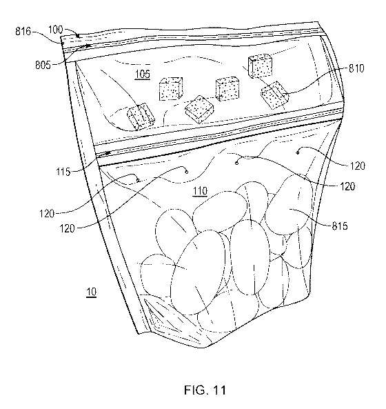
[0055] FIG. 11 is a perspective view of a bag 100 of FIG. 1. The bag 100 can
be used
with various types of edible goods 815, 820 provided in the upper chamber 105
and in the
lower chamber 110. As illustrated, a first type of edible goods 810 (e.g.,
butter, margarine,
salt, pepper, garlic, spices, etc., alone or in combination) are provided in
the upper chamber
105. A second type of edible goods 815 (e.g., potatoes) may be provided in the
lower
11
CA 03071400 2020-01-28
WO 2019/028154 PCT/US2018/044833
chamber 110. The releasable seal 115 may keep the first type of edible goods
810
separate from the second type of edible goods 815 for transport, storage, etc.
A plurality of
ventilation openings 120 are provided in the bag 100 to allow fluid
communication
between the interior of the lower chamber 110 and the atmosphere 10
surrounding the
bag. Additionally, in some embodiments, the upper edge 805 of the bag 100 may
be a tear
away portion to allow the bag 100 to be opened. For example, a notch 816 may
be present
enabling the upper edge 805 of the upper chamber 105 to be torn away. In some
embodiments the bag 100 can have one or more notches 816.
[0056] The bag 100 may be heated (e.g., using a microwave oven or other
heating
source). As bag 100 is heated, each of the first type of edible goods 810 and
the second
type of edible goods 815 are separately heated in their respective upper
chamber 105 and
lower chamber 110. In some embodiments, as each of the first type of edible
goods 810
and the second type of edible goods 815 are heated, steam or other gaseous
food material
may build up in the upper chamber 105 and the lower chamber 110, increasing
internal
pressure within. As the internal pressure increases in the upper chamber 105
and the
lower chamber 110, the stress created by the increased pressure may be applied
to
releasable seal 115. When the pressures within the upper chamber 105 and the
lower
chamber 110 exceed a threshold, the releasable seal 115 will release and
gravity may pull
the first type of edible goods 810 toward the second type of edible goods 815
mixing the
two types of edible goods 810, 815.
[0057] Alternatively, the releasable seal 115 may be configured to release in
response to
an internal temperature within the upper chamber 105 and lower chamber 110
exceeding
a threshold. For example, releasable seal 115 may be formed from a material
having a
specific rigidity below the threshold temperature but may become sufficiently
elastic above
the threshold temperature. The elasticity can be such that the releasable seal
releases or
opens in response to internal pressure to allow fluid communication between
the upper
chamber 105 and the lower chamber 110. This can allow the first type of edible
goods 810
to mix with the second type of edible goods 815
[0058] Further, in some example implementations, the releasable seal 115 may
be
configured to release in response to a combination of an internal temperature
and internal
pressure within the upper chamber 105 and lower chamber 110 exceeding a
threshold.
For example, the releasable seal 115 may be formed from a material having a
rigidity that
decreases in response increasing temperature. As the rigidity decreases (the
material
becomes more elastic) the adhesion of the seal decreases. The ability of the
seal to
withstand internal pressure decreases as the temperature increases. Therefore,
a tradeoff
can be made between the temperature and the pressure at which the releasable
seal will
release.
12
CA 03071400 2020-01-28
WO 2019/028154 PCT/US2018/044833
[0059] The openings 120 providing fluid communication between the exterior
atmosphere 10 surrounding the storage bag 100 and the lower chamber 110 allow
control
of the pressure within the lower chamber 110 to ensure the releasable seal 115
does not
release prematurely (e.g., before the first type of edible goods 810 and the
second type of
edible goods 815 are sufficiently cooked). The openings 120 can further ensure
that the
lower chamber 110 does not release somewhere other than at the releasable
seal. The
number and size of the ventilation openings 120 may be selected such that
during heating
of the storage bag 100, the pressure within the lower chamber 110 increases at
a
particular rate such that edible goods in the upper chamber 105 and the lower
chamber
110 are substantially cooked prior to the releasable seal 115 rupturing. For
example, for
the second type of edible goods 815 being potatoes, eight (8) ventilation
openings having
an average diameter of 1-1.5 mm may provide sufficient ventilation to control
release of the
releasable seal 115 until the potatoes are sufficiently cooked (approximately
6 minutes).
The number of the openings can vary, as can their size, in relation to the
amount of edible
goods.
[0060] FIG. 12 is another perspective view of the bag of FIG. 1. The bag 100
is shown
with the first type of edible goods 810 and the second type of edible goods
815 after
heating. As illustrated, releasable seal 115 has released and the first type
of edible goods
810 (e.g., butter, margarine, salt, pepper, garlic, spices, etc., alone or in
combination) has
mixed or coated the second type of edible goods 815 (e.g., potatoes) in the
lower chamber
110. The bag 100 is shown inflated due to, for example, the release of steam
and other
vapors from the cooked second type of edible goods 815. The first type of
edible goods
810 is shown dispersed about the second type of edible goods 815 and is
depicted as
scattered circles and triangles representing, for example, spices or other
seasonings.
[0061] In some embodiments, pressure may increase in only one of the upper
chamber
105 and the lower chamber 110. For example, in the example, of FIG. 12, if the
first type of
edible foods 810 is a seasoning, it may not produce an appreciable amount of
steam or
other gaseous food when heated. Therefore, the increased pressure that
releases the
releasable seal 115 may originate in (predominantly) the lower chamber 110, as
for
example, the second edible goods 815 produces steam as it cooks.
[0062] Alternatively, the releasable seal 115 may be configured to release in
response to
an internal temperature within the upper chamber 105 and lower chamber 110
exceeding
a threshold. For example, releasable seal 115 may be formed from a material
having a
specific rigidity below the threshold temperature but may become sufficiently
elastic above
the threshold temperature such that the releasable seal may release in
response to internal
pressure to allow fluid communication between the upper chamber 105 and the
lower
chamber 110.
13
CA 03071400 2020-01-28
WO 2019/028154 PCT/US2018/044833
[0063] Further, in some example implementations, the releasable seal 115 may
be
configured to release in response to a combination of an internal temperature
and internal
pressure within the upper chamber 105 and lower chamber 110 exceeding a
threshold.
For example, the releasable seal 115 may be formed from a material having a
rigidity that
decreases in response increasing temperature. As the rigidity decreases (the
material
becomes more elastic) the adhesion of the seal decreases. The ability of the
seal to
withstand internal pressure decreases as the temperature increases. Therefore,
a tradeoff
can be made between the temperature and the pressure at which the releasable
seal will
release.
[0064] The bag 100 may now be opened and the combination of the first type of
edible
goods 810 and the second type of edible goods 815 may be consumed. For
example, the
upper edge 805 of the bag 100 may be torn away to allow the bag 100 to be
opened.
Other mechanisms for opening the bag 100 may be apparent to a person of
ordinary skill in
the art.
[0065] Though potatoes are illustrated as the second type of edible goods 815
in FIG. 8
and FIG. 9, example implementations are not limited to these edible goods and
other edible
goods may be apparent to a person of ordinary skill in the art.
[0066] The foregoing detailed description has set forth various embodiments of
the
devices and/or processes via the use of block diagrams, schematics, and
examples.
Insofar as such block diagrams, schematics, and examples contain one or more
functions
and/or operations, each function and/or operation within such block diagrams,
schematics,
or examples can be implemented, individually and/or collectively.
[0067] While certain embodiments have been described, these embodiments have
been
presented by way of example only, and are not intended to limit the scope of
the protection.
Indeed, the novel methods and apparatuses described herein may be embodied in
a variety
of other forms. Furthermore, various omissions, substitutions and changes in
the form of
the methods and systems described herein may be made without departing from
the spirit
of the protection. The accompanying implementations and their equivalents are
intended
to cover such forms or modifications as would fall within the scope and spirit
of the
protection.
[0068] Although the present disclosure provides certain example embodiments
and
applications, other embodiments that are apparent to those of ordinary skill
in the art,
including embodiments which do not provide all of the features and advantages
set forth
herein, are also within the scope of this disclosure. Accordingly, the scope
of the present
disclosure is intended to be defined only by reference to the appended claims.
14