Note: Descriptions are shown in the official language in which they were submitted.
1
CIGARETTE PACK AND METHOD OF PRODUCING THE SAME
This application is a divisional of Canadian Application Serial No. 2783065
filed on July 17, 2012.
Description
The invention relates to packs having an outer wrapper made of sheet material,
in particular
cigarette packs, configured according to the preamble of Patent Claim 1.
In particular cigarette packs are usually provided with a specially designed
blank which, in
particular for fiscal reasons, has to be destroyed when the pack is opened for
the first time. This
applies to the revenue-stamp label which is customary in many countries.
It is known for the (revenue-stamp) label to be positioned such that, when the
outer wrapper
made of sheet material is severed by means of a tear-open strip or tear-open
thread, the label is
severed and thus rendered invalid. For this purposes, the label is positioned
on the inside of the
inner wrapper by means of glue, to be precise in the region of the inner tear-
open strip, and
therefore the label is severed upon actuation of the tear-open strip (EP 0 803
450 B1). It is also
known for the label, in addition, to be connected permanently to the pack.
Upon actuation of the
tear-open strip, the label is severed, but the resulting pieces remain on the
pack in their entirety
when the outer wrapper is removed (EP 0 895 946 B1).
The invention further develops, and improves, the technology of destroying
labels in packs with
an outer wrapper made of sheet material. The object on which the invention is
based consists in
designing, and arranging, the label, the outer wrapper and/or the tear-open
strip such that, for
all embodiments of (cuboidal) pack, it is possible to ascertain that the label
has been rendered
invalid.
In order to achieve this object, the pack according to the invention is
designed with the features
of the characterizing part of Claim 1.
Accordingly, in the case of the pack according to the invention, it is
achieved that, upon
actuation of the tear-open means for the outer wrapper and/or upon removal of
the said outer
wrapper, at least one piece of the label is removed, that is to say on account
of corresponding
CA 3071741 2020-02-07
2
connection to the outer wrapper. At least one other, defined piece of the
label remains on the
pack, and therefore, even once the outer wrapper has been removed, the
original presence of a
label and the fact that the latter has been destroyed can be ascertained
exclusively by way of
the pack.
The (rectangular) label is provided preferably with at least one weakening
line, in particular one
perforation line, which runs essentially transversely to the longitudinal
extent and is positioned
such that the piece(s) of the label remaining on the pack upon removal of the
outer wrapper is
(are) bounded by a defined, precise peripheral edge ¨ on account of the
weakening line.
In order to bring about the specific severing or division of the label during
the opening operation,
this label is connected to the pack, on the one hand, and to the inside of the
outer wrapper, on
the other hand, by means of defined (glue) connections, wherein regions of
glue, in particular
strips of glue or spots of glue, are assigned to the one piece for connection
to the pack and the
other piece for connection to the outer wrapper. Of further significance is
the fact that the
weakening line of the label influences the shape of, or course taken by, the
tear lines or tear
edges produced in the sheet material of the outer wrapper by the tear-open
strip, in particular by
way of oblique or diverging weakening lines. The tear-open strip, for severing
the outer wrapper,
is arranged in a particular position, on the one hand, relative to the areas
of glue, which are
arranged on different sides of the label, and, on the other hand, relative to
the perforation line or
the perforation lines, and therefore, upon removal of the outer wrapper,
severing takes place
between the pieces assigned to the pack, on the one hand, and the pieces
assigned to the outer
wrapper, on the other hand.
For the production of packs designed according to the invention, use is made
preferably of
methods and apparatuses which constitute a further development of conventional
technologies
(EP 0 895 946 B1). According to a first embodiment of the method and of the
apparatus, a
continuous (sheet-material) web for the outer wrapper is provided in a
correctly positioned
manner, by means of a glue head, with areas of glue, in particular with areas
of PSA (pressure
sensitive adhesive), in order for the label to be positioned on the web. This
adhesive is applied
by a hot-melt process. In a subsequent (second) glue station, the label is
provided with glue on
the free side ¨ with offset relative positioning ¨ in order to be connected to
the pack. The glue
applied in this second glue station may likewise be permanent PSA. As an
alternative, it is
CA 3071741 2020-02-07
3
possible for conventional hot-melt adhesive to be applied to the free side of
the label fixed on
the web, in order to form the areas of glue which connect the label to the
pack. Following
completion of the pack, these areas of glue are activated by heat and
pressure.
A further alternative of the method consists in the operation of connecting
the label, which is
fixed (in the first instance) on the web, to the pack being carried out
separately from the
preparation of the web. In this case, glue, in particular cold-setting glue,
is applied to the packs
supplied to a blank station, to be precise specifically in the region of the
label which is to be
placed in position. When the blank for the outer wrapper (provided with label)
is folded around
the pack, this causes the label to be connected to the pack via the areas of
glue applied to the
pack.
According to a further alternative, glue can be applied to the separately
supplied labels. In a first
method step, separate labels are provided with (cold-setting) glue on a side
facing the packs
.. and are then placed in the correct position on the pack. Thereafter, glue,
preferably
conventional hot-melt adhesive, is applied to the free outer side of the label
(on the pack) in an
offset position. The blank is then folded in the conventional manner and the
hot-melt adhesive is
activated by heat.
Further details of the pack and of the production method will be explained in
more detail
hereinbelow with reference to the drawings, in which:
Fig 1 shows a perspective illustration of a (cigarette) pack with an
outer wrapper and
label,
Fig 2 shows, on an enlarged scale, the pack according to fig 1 in a
horizontal section
taken along section plane II-II in fig 1,
Fig 3 shows a perspective illustration of the pack according to fig
1 during a phase of
outer-wrapper removal,
Fig 4 shows an illustration corresponding to fig 1 for a different
exemplary embodiment,
Fig 5 shows, on an enlarged scale, a horizontal section taken along section
plane V-V
from fig 4,
Fig 6 shows an illustration analogous to fig 3 relating to the
exemplary embodiment of
fig 4,
CA 3071741 2020-02-07
4
Fig 7 shows a further exemplary embodiment of a pack in an
illustration analogous to
figs 1 and 4,
Fig 8 shows, on an enlarged scale, a horizontal section VIII-VIII in
fig 7,
Fig 9 shows an illustration analogous to figs 3 and 6 relating to
the exemplary
embodiment of fig 7,
Fig 10 shows a schematic side view of an apparatus for positioning
labels and outer
wrappers on packs, and
Fig 11 shows, likewise in a schematic side view, another embodiment
of an apparatus
for producing packs with an outer wrapper and label.
Packs 10 for sensitive consumer goods, in .particular for cigarettes, are
often enclosed by an
outer wrapper 11 made of sheet material in order to protect the pack contents.
The pack 10 and
outer wrapper 11 form, in conceptual terms, a pack unit. The exemplary
embodiments shown
relate to cigarette packs 10 made of thin cardboard. In concrete terms, a pack
10 of the "shell
and slide" type is shown. The latter comprises, as standard, an inner pack,
that is to say a slide
12, and an outer pack, that is to say a shell 13. The slide 12 is usually
designed as a tray-like
container. The shell 13 comprises an essentially rectangular blank which is
folded to form a
cross-sectionally rectangular hollow body which is open at both ends. A (large-
surface-area)
rear wall 14 has a flap connection 15, that is to say a peripheral flap, which
is connected to a
wall flap of the rear wall 14 by adhesive bonding.
The outer wrapper 11 preferably comprises a sheet-material blank which fully
encloses the pack
10. In the case of the present embodiment, the outer wrapper 11 is folded
around the 10 such
that an end side or front side 16 of the pack 10 ¨ in the case of the present
exemplary
embodiment an upper, open side of the shell 13 ¨ has a continuous, closed
covering or wall of
the outer wrapper 11. Opposite, in the region of a base wall (not shown),
sheet-material flaps
overlap. Furthermore, complex folds, that is to say so-called envelope folds,
are provided in the
region of narrow side surfaces of the outer wrapper 11.
In order to open the pack 10 for the first time, the outer wrapper 11 is
wholly or partially
removed. An opening aid, configured as a tear-open strip 19 or tear-open
thread is provided for
this purpose. The tear-open strip 19 extends preferably around the pack 10, in
the present case
in the region of a front side, rear side 14, base side and front side 16, to
be precise
CA 3071741 2020-02-07
5
(approximately) in a vertical (imaginary) centre plane. The tear-open strip 19
is connected to the
blank of the outer wrapper 11 on the inside throughout, preferably by adhesive
bonding.
In order to grip the tear-open strip 19 upon opening of the pack unit, a grip
tab 20 is formed at a
free end. Gripping this grip tab 20 and pulling the tear-open strip 19 causes
the latter to sever
the sheet material of the outer wrapper 10 continuously on either side. In the
case of the present
example for the arrangement of the tear-open strip 19, removal of the latter
gives rise to two
cap-like part-wrappers 21, 22, which can be pulled off laterally from the pack
10 (fig 3). The grip
tab 20 is preferably arranged at the bottom, in the region of a base wall
and/or opposite to the
front side 16, and is exposed, for manual gripping purposes, on the rear side
of the pack unit or
the rear wall 14.
The pack 10 or the pack unit is provided with a separate blank, that is to say
a label 23, which,
when the pack unit is opened for the first time, should be destroyed and
partially removed. The
label 23 is, in particular, a fiscal or revenue-stamp label. This should be
placed in position such
that it is destroyed by the initial-opening operation.
The label 23 here is positioned on a large-surface-area wall of the pack 10,
in the present case
on the rear wall 14 of the shell 13, to be precise adjacent to an upper
periphery of the rear wall
14 and adjacent to the front side 16. The rectangular, elongate or strip-like
label 23 extends
transversely to the longitudinal extent of the pack 10.
The pack unit is designed such that the label 23 is divided by the outer
wrapper 11 being
removed, in particular by means of the tear-open strip 19. As a result, at
least one piece 24 of
the label 23 should remain on the pack 10, that is to say should remain
connected to the same.
At least one other piece 25 of the label 23 adheres to the outer wrapper 11,
and is thus
disposed of. For this purpose, the label is connected to the pack 10, on the
one hand, and to the
inside of the outer wrapper 11, on the other hand, that is to say at a
different location, by
different connecting means, in the present case by glue. The tear-open strip
19 is positioned
between the functionally associated connecting locations of the label 23, and
therefore at least
two pieces 24, 25 of the label 23 are produced directly or indirectly by the
label 23. The label 23
is severed directly by the tear-open strip 19, which, for this purpose, runs
on the inside of the
label 23, that is to say between the label 23 and the pack 10 or rear wall 14.
CA 3071741 2020-02-07
6
In the case of the exemplary embodiment according to figs 1 to 3, the label 23
is connected to
the pack 10, in this case to the rear wall 14, by a first strip 26 of glue.
The strip 26 of glue
extends peripherally more or less over the entire width of the label 23. At
least one further glue
connection or a further strip 27 of glue is arranged at a distance from the
first strip 26 of glue,
and essentially parallel to the same, to be precise on the opposite side of
the label 23, in order
to connect the latter to the inside of the outer wrapper 11. The tear-open
strip 19 is positioned
between these two strips 26, 27 of glue, with the result that, upon actuation
of the tear-open
strip 19, the label 23 is severed between the strips 26, 27 of glue, which act
on opposite sides.
The piece 24 with the strip 26 of glue remains connected to the pack 10 and
the piece 25 with
the strip 27 of glue remains connected to the outer wrapper 11.
The dimensioning of the label 23 gives rise, in the present case, to the
provision of a third strip
28 of glue, which is arranged in the region of the piece 25, for connecting
the label 23 to the
outer wrapper 10, likewise parallel to, and at an equal distance from, the
adjacent strip 27 of
glue, and therefore the label 23 is fixed by glue, overall, in a manner
corresponding to its
geometrical shape.
A further special feature is the arrangement of at least one weakening line in
or on the label 23,
in the present case a perforation line 29 extending transversely to the label
23 over the entire
width of the same. The arrangement in figs 1 to 3 means that the perforation
line 29 is located
parallel to the tear-open strip 19, and at a small distance from the same, on
the side assigned to
the strip 26 of glue. Upon actuation of the tear-open strip 19, the piece 24
(on the pack 10) is
thus provided with a precise, defined boundary, that is to say corresponding
to the weakening
line (fig 3). A further perforation line can, as an alternative, be positioned
on the other side of the
tear-open strip 19, that is to say adjacent to the strip 27 of glue. At any
rate, a relatively small
piece 24 of visually pleasing form is connected permanently to the pack 10. A
remaining piece
of the label 23, upon actuation of the tear-open strip 19, is gripped by the
latter and removed
from the label 23 on account of the tear-open strip 19 being connected to the
label 23 by
adhesive (fig 3).
The embodiment according to figs 4 to 6 shows, by way of example, the same
embodiment of
pack 10 (slide/shell pack). The outer wrapper 10 with tear-open strip 19 is
also arranged in the
same way.
CA 3071741 2020-02-07
7
In the case of this exemplary embodiment, the label 23 is fixed such that,
upon severing or
removal of the outer wrapper 11, the label 23 is severed into the pieces 24,
25.
In the case of this example, the tear-open strip 19 is involved only
indirectly in the severing of
the label 23 and is located in the region of the outside of the label 23, that
is to say between the
label 23 and outer wrapper 11 (fig 5). Accordingly, the tear-open strip 19
acts, as in the case of
conventional packs, exclusively for severing the outer wrapper 11. The latter
is pulled off or
removed from the pack 10 in order to give rise to the severing action into
pieces 24, 25. For this
purpose, the first (larger) piece 24 is fixed to the pack 10 ¨ rear wall 14 ¨
via glue connections,
in the present case via spots 31 of glue, and in the region of the piece 25 is
fixed to the inside of
the outer wrapper 11 likewise by spots 32 of glue. The spots 31, 32 of glue
are arranged in rows
33, 34 of spots in the longitudinal direction of the label 23, to be precise
in respect of the spots
31 of glue, on the one hand, and spots 32 of glue, on the other hand, on
different sides of the
label 23. The spots 32 of glue, for fastening the piece 25 on the outer
wrapper 11, have a larger
surface area than the remaining spots 31 of glue. The spots 31,32 of glue
preferably consist of
hot-melt adhesive. A weakening line or perforation line 29 is arranged, in
turn, in a region
between the differently acting spots 31, 32 of glue, and therefore the piece
24, which remains
on the pack 10, has the correct severing edge.
The exemplary embodiment according to figs 7 to 9 is designed in the manner
described as far
as the pack unit is concerned, that is to say as far as the pack 10 and the
outer wrapper 11 are
concerned. The innovative special feature relates to the label 23. The latter
is positioned
preferably approximately centrally on the pack 10 (rear wall 14). By means of
(two) weakening
lines or perforation lines 35, 36 arranged at an angle to one another, the
label 23, upon opening
of the pack unit or of the outer wrapper 11, is divided up into three pieces,
that is to say the
pieces 37, 38 (permanently) connected to the pack 10 and a third piece 39,
which is removed
with the outer wrapper 11 and/or with the tear-open strip 19.
The label 23 is connected, in a manner corresponding to this division, to the
pack 10, on the one
.. hand, and to the outer wrapper 11, on the other hand, by areas of glue.
Spots 31 of glue are
provided, to be precise in rows 33, 34 of spots, in the region of the pieces
37, 38. Overall, in the
present case four spots 31 of glue are assigned to each piece 37, 38.
CA 3071741 2020-02-07
8
The (central) piece 39 is positioned on the outer wrapper 11 by means of strip
40 of glue. The
strip 40 of glue extends transversely over the label 23. In the present case,
the strip 40 of glue is
arranged in the region of the tear-open strip 19 which ¨ like the strip 40 of
glue ¨ is positioned
between the label 23 and outer wrapper 11. Accordingly, the label 23 is
connected in this region
¨ piece 39 ¨ to the outer wrapper 11 and the tear-open strip 19. The strip 40
of glue is
preferably wider than the tear-open strip 19.
The perforation lines 35, 36, which diverge in the opening or tear-open
direction and are
arranged, in particular, in a wedge-shaped manner, influence the course taken
by tearing lines
41, 42 of the sheet-material strip removed from the outer wrapper 11 (bottom
of fig 9). The
converging peripheries of the piece 39 mean that, as the tear-open movement
continues, the
removed sheet-material strip is also wedge-shaped, the tearing tearing lines
41, 42 diverging in
the tear-open direction. This has an effect on the configuration of the
resulting part-wrappers 21,
22, which are still narrow on one side (at the bottom). This makes it easier
to remove the part-
wrappers 21, 22. The operation of removing the outer wrapper 11 in full is
rendered easier
overall. The piece 39 remains connected to the tear-open strip 19 and/or the
removed wedge
piece of sheet material. Trapezoidal pieces 37, 38 are located on the pack 10¨
rear wall 14.
On account of particular production methods and/or their function, the areas
26, 27, 28 or 31, 32
or 40 of glue on the label 23 consist of hot-melt adhesive or cold-setting
glue. The procedure
may also be such that the label 23 (with the areas of glue) is transferred
onto a continuous web
of the sheet material, and therefore a blank making up the outer wrapper 11,
and prepared
completely in respect of the label and the areas of glue, is folded around the
pack 10. As an
alternative, glue can be applied to the label in the region of a label
apparatus and then on the
free side of the label 23 positioned on the pack 10.
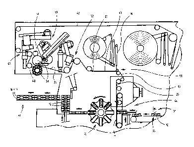
The technology illustrated in fig 10 is particularly suitable for the
embodiment according to figs 1
to 3. Blanks for the outer wrapper 11 are severed from a continuous (sheet-
material) web 43 in
the region of a blank station 44 and folded around the pack 10 with the aid of
a folding turret 45.
The packs 10 are transported by a supply conveyor 53 in the region of the
blank station 44 with
their longitudinal extent oriented in a conveying direction. The blank of the
outer wrapper 11, in
a first folding step, is folded in a U-shaped manner around the pack in the
longitudinal direction
of the same. Thereafter, the folds are formed in the region of the side
surfaces 18 and, finally,
CA 3071741 2020-02-07
9
the fold is formed in the region of a (rearwardly directed) base surface. The
(finished) pack units
10, 11 then pass into the region of a sealing station 46, in which the folds
of the outer wrapper
11 on the (sideways directed) side surfaces 18 are sealed by heat and
pressure.
In the region of a first glue subassembly 47, the web 43 is provided with
glue, to be precise with
regions of glue which serve for connecting the labels 23 to the web 43. In the
case of the
embodiment according to figs 1 to 3, accordingly, two parallel strips 27, 28
of glue are applied to
the web 43 by correspondingly cyclic actuation of the glue subassembly 47.
Preferably, PSA,
that is to say a permanently adhering glue, is transferred onto the web 43 by
a hot-melt process.
In a subsequent transfer station 48, labels 23 are placed and/or pressed in a
precisely
positioned manner onto the web 43, that is to say in the region of the strips
27, 28 of glue. The
labels 23 are supplied individually by a label subassembly 49 and placed on
the web 43 by a
pair 50 of rollers. An (upper) roller is assigned a perforation mechanism for
producing the
transversely directly perforation line 29, in this case a blade roller 51 with
a circulating
perforation blade.
The web 43 then runs through a further gluing station with a glue subassembly
52. The latter is
designed in a manner analogous to the glue subassembly 47 and is controlled
such that glue is
applied to the outside of the labels 23 for connection to the pack 10. In the
case of the
exemplary embodiment according to figs 1 to 3, this glue is in the form of the
strips 26 of glue.
The areas of glue on the free side of the labels 23 can likewise consist of
PSA or, as an
alternative, of conventional hot-melt adhesive.
The web 43 with the labels 23 then passes into the region of a transfer
station 59, in which a
tear-open strip 19 is applied in the form of a continuous strip ¨ coming from
a reel ¨ to the web
43 and connected thereto by means of glue throughout. In the region of the
labels 23, the tear-
open strip 19 is connected to the free (upwardly directed) side of the label
23, to be precise in a
position between the areas 26 of glue, on the one hand, and the areas 27, 28
of glue, on the
other hand. The tear-open strip 19 is placed in position, in the present case,
centrally on the
web 43.
CA 3071741 2020-02-07
10
A further, special alternative consists in glue for connecting the label 23 to
the pack 10 being
applied to the latter and in the connection being made thereafter. The packs
10 are provided
with glue (in the region of the label 23 which is to be placed in position) as
they are being
supplied to the blank station 44, and are then provided with the outer wrapper
11 in the region of
the blank station 44. The glue, preferably spots of cold-setting glue, is
applied to the upwardly
directed, free (rear) wall 14 of the pack. For this purpose, a gluing
mechanism 55, preferably
with glue nozzles, is arranged above the (horizontal) movement path of the
packs 10.
The web 43 prepared in the manner described passes into the region of the
blank station 44.
There, blanks for the outer wrapper 11 are severed from the web 43 and folded,
in a folding
process which is known in principle, around the packs 10. If use is made of
areas of glue which
consist of hot-melt adhesive which can be reactivated by means of heat, this
supply of heat can
take place in the region of a shrink-wrapping station 57 for handling packs 10
with an outer
wrapper 11 made of shrink-wrapping sheet material.
The technology according to fig 11 is particularly suitable for packs with
applications of glue
running the longitudinal direction of an (elongate) label, that is to say, in
the present case, for
processing labels 23 with rows 33, 34 of spots 31, 32 of glue.
The (sheet-material) web 43, which, in this exemplary embodiment too, is
pulled off from reels,
in the first instance is provided continuously with the tear-open strip 19 (by
adhesive bonding in
the region of the transfer station 58). The thus conventionally prepared web
43 (with centrally
running tear-open strip 19) is supplied to the blank station 44 in order for
the blanks of the outer
wrapper 11 to be produced by severing from the web 43.
In the case of this technology, the label 23 is supplied to the pack 10 (in
the glued state),
connected to the same and provided on the free side with the necessary areas
of glue. On the
supply conveyor 53, a belt conveyor with stops for each pack 10, the packs 10
are moved past
a label apparatus 54, which is positioned above the supply conveyor 53, and a
label 23 is
placed in position on each pack 10. The label 23 is provided with glue on the
side facing the
pack 10 and is fixed by means of a pressure-exerting mechanism (belt). In the
label apparatus
54, each label 23 is provided with the transversely directed perforation line
29. Furthermore, a
gluing mechanism 55 applies glue to the free side of the label 23. In the
present case, rows 33,
CA 3071741 2020-02-07
11
34 of spots 31, 32 of glue ¨ in particular cold-setting glue ¨ are applied, by
glue nozzles, to the
label 23, which has the longitudinal extent oriented in the conveying
direction. These spots of
glue constitute areas of glue by which the label 23 is fixed on the pack 10
(rear wall 14). The
label apparatus 54 is preferably designed in a manner corresponding to the
illustration and
description in WO 2007/087885 Al, albeit with the proviso that the label 23 is
applied
(approximately) centrally to the pack 10.
Since, in the region of the label apparatus 54, the labels 23 have the
longitudinal extent oriented
in the conveying direction, the rectangular or cuboidal packs 10 on the supply
conveyor 53,
accordingly, are oriented transversely to the conveying direction, and
therefore the label 23 can
be positioned as shown (longitudinal extent transverse to the rear wall 14).
The rear wall 14
here is directed upwards.
Following the label apparatus 54, the pack 10 is rotated through 90 in a
horizontal plane in a
rotary station 58 (not illustrated in detail). The pack 10 is then positioned
such that it has the
longitudinal extent oriented in the conveying direction, where the front side
16 is located at the
front, as seen in the movement direction. This makes possible the
abovedescribed position of
the outer wrapper 11 with the folds.
Prior to the packs 10 being pushed into the folding turret 45 and/or prior to
the outer wrapper 11
being placed in position, glue is applied to the free side of the label 23 (on
the pack 10). For this
purpose, a further gluing mechanism 56 is positioned in the region of the
supply conveyor 53, or
upstream of the blank station 44, above the movement path of the packs 10
(following rotation
of the same). This gluing mechanism 56 applies glue (spots of glue) to the
label 23 in order to
connect the same to the outer wrapper 11. In the case of the exemplary
embodiment of figs 4 to
6, accordingly, the spots 32 of glue, in particular two spots 32 of glue, are
applied by nozzles of
the gluing mechanism 56. These spots of glue consist preferably of hot-melt
adhesive.
Following the folding turret 45, the pack units 10/11 are folded to completion
and supplied to a
.. sealing station 46 for sealing the folds of the side surfaces 18.
Thereafter, the packs pass into
the region of a shrink-wrapping station 57 (for example configured according
to
EP 1 084 954 B1), in which heat is transmitted in order for an appropriately
designed sheet
material of the outer wrapper 11 to be subjected to shrink-wrapping treatment.
The heat applied
CA 3071741 2020-02-07
12
also causes the spots 32 of glue to be activated and thus causes the label 23
to be connected
to the outer wrapper 11.
The technology described above can also be used for other types of pack,
preferably for hard
packs, to be precise also in the case of the tear-open strip 19 being arranged
transversely to the
large-surface-area pack sides. The label 23 may also be arranged in the
longitudinal direction of
the pack. It is also possible to use patterns of glue other than those
illustrated, although the
patterns of glue and the types of glue have to be fit for purpose.
CA 3071741 2020-02-07
13
List of designations
Pack 41 Tearing line
11 Outer wrapper 42 Tearing line
12 Slide 43 Web
13 Shell 44 Blank station
14 Rear wall 45 Folding turret
Flap connection 46 Sealing station
16 Front side 47 Glue subassembly
17 Outer flap 48 Transfer station
18 Side surface 49 Label subassembly
19 Tear-open strip 50 Pair of rollers
Grip tab 51 Blade roller
21 Part-wrapper 52 Glue subassembly
22 Part-wrapper 53 Supply conveyor
23 Label 54 Label apparatus
24 Piece 55 Gluing mechanism
Piece 56 Gluing mechanism
26 Strip of glue 57 Shrink-wrapping station
27 Strip of glue 58 Rotary station
28 Strip of glue 59 Transfer station
29 Perforation line
Remaining piece
31 Spot of glue
32 Spot of glue
33 Row of spots
34 Row of spots
Perforation line
36 Perforation line
37 Piece
38 Piece
39 Piece
Strip of glue
CA 3071741 2020-02-07