Note: Descriptions are shown in the official language in which they were submitted.
CA 03071833 2020-01-31
WO 2019/045923 PCT/US2018/044089
HIGH QUALITY SPHERICAL POWDERS FOR ADDITIVE MANUFACTURING PROCESSES
ALONG WITH METHODS OF THEIR FORMATION
PRIORITY INFORMATION
[0001] The present application claims priority to U.S. Provisional Patent
Application Serial No.
62/551,981 titled "High Quality Spherical Powders for Additive Manufacturing
Processes Along
with Methods of Their Formation" filed on Aug. 30, 2017, which is incorporated
by reference herein.
FIELD
[0002] The present invention generally relates to systems and methods for
forming high quality
spherical powders from a metallic powder feedstock. The high quality spherical
powders are
particularly suitable for additively manufacturing an object or part.
BACKGROUND
[0003] Additive manufacturing processes generally involve the buildup of
one or more materials
to make a net or near net shape (NNS) object, in contrast to subtractive
manufacturing methods.
Though "additive manufacturing" is an industry standard term, additive
manufacturing encompasses
various manufacturing and prototyping techniques known under a variety of
additive manufacturing
terms, including freeform fabrication, 3D printing, rapid prototyping/tooling,
etc. Additive
manufacturing techniques are capable of fabricating complex components from a
wide variety of
materials. Generally, a freestanding object can be fabricated from a computer
aided design (CAD)
model.
[0004] A particular type of additive manufacturing process uses an energy
beam, for example, an
electron beam or electromagnetic radiation such as a laser beam, to sinter or
melt a powder material,
creating a solid three-dimensional object in which particles of the powder
material are bonded
together. Different material systems, for example, engineering plastics,
thermoplastic elastomers,
metals, and ceramics are in use. Laser sintering or melting is also a notable
additive manufacturing
process for rapid fabrication of functional prototypes and tools. Applications
include patterns for
investment casting, metal molds for injection molding and die casting, and
molds and cores for sand
casting. Fabrication of prototype objects to enhance communication and testing
of concepts during
the design cycle are other common usages of additive manufacturing processes.
[0005] Laser sintering is a common industry term used to refer to producing
three-dimensional
(3D) objects by using a laser beam to sinter or melt a fine powder. More
accurately, sintering entails
1
CA 03071833 2020-01-31
WO 2019/045923 PCT/US2018/044089
fusing (agglomerating) particles of a powder at a temperature below the
melting point of the powder
material, whereas melting entails fully melting particles of a powder to form
a solid homogeneous
mass. The physical processes associated with laser sintering or laser melting
include heat transfer to
a powder material and then either sintering or melting the powder material.
[0006] In this process, the physical and chemical characteristics of the
powder material can
impact the quality of the resulting object. That is, the properties of a
component built through
additive manufacturing depends on the metal powder itself, with higher quality
powders (e.g.,
denser, cleaner, and more spherical) behaving more predictably and thus
results in better parts. As
such, high quality powder material is required for components formed from
Additive Manufacturing
techniques, particularly when used to manufacture components for gas turbine
machinery and/or
medical implant or devices applications.
[0007] Powder making methods from a metal source mainly (as there are other
techniques like
hydride/dihydride, ball milling, rotating electrode, plasma atomization etc.)
include gas atomization
and water atomization. Generally, gas atomization techniques result in
particles with a more
spherical and consistent shape, while water atomization techniques result in
particles with an
irregular shape. Additionally, due to the presence of oxygen in water, an
oxidized layer may form on
the outside of the particles formed by water atomization techniques.
Currently, powders from gas
atomization techniques are preferred for additive manufacturing over powders
formed from water
atomization techniques, since powders formed from gas atomization techniques
are more regular in
shape (e.g., more spherical) and have a limited oxidized layer thereon.
[0008] However, powders formed from gas atomization are much more expensive
to produce
than water atomization powders. Thus, the cost of the resulting component
formed from a gas
atomized powder is high. As such, a need exists for reducing the cost of high
quality powders for
additive manufacturing for higher adoption, while retaining control of the
physical and chemical
characteristics of the powder material.
BRIEF DESCRIPTION
[0009] Aspects and advantages will be set forth in part in the following
description, or may be
obvious from the description, or may be learned through practice of the
invention.
[0010] Methods are generally provided for forming a high-quality powder
from a feedstock
powder of feedstock particles having irregular shapes. In one embodiment, the
method includes
exposing the feedstock powder to a plasma field to form a treated powder of
treated particles having
a more spherical shape than the feedstock particles. Prior to the plasma field
exposure, the feedstock
2
CA 03071833 2020-01-31
WO 2019/045923 PCT/US2018/044089
particles have an oxidized layer thereon as a result from previous exposure to
water. After exposure
to the plasma field, the treated particles are substantially free from an
oxidized layer.
[0011] In one embodiment, the feedstock powder may be formed from water
atomization,
mechanical crushing or grinding, gas atomization, and/or plasma atomization.
For example, the
oxidized layer on the feedstock particles may be a result of exposure to water
during a water
atomization process that formed the feedstock particles, or from exposure to
water vapor in the air
during mechanical grinding.
[0012] To expose the feedstock powder to the plasma field, the method may
include introducing
the feedstock powder into the plasma field such that the surface of the
feedstock particles melts
and/or evaporates to form the more spherical shape.
[0013] In particular embodiments, the plasma field includes a reducing
component that reacts
with the oxidized layer on the feedstock particles, such as hydrogen, carbon
monoxide, or a mixture
thereof.
[0014] Through such a method, the treated particles may have an average
particle size that is less
than an average particle size of the feedstock particles. For instance, the
treated particles may have
an average particle size that is about 10% to about 90% of the average
particle size of the feedstock
particles.
[0015] The feedstock particles may be formed from a metal material, such as
a pure metal, an
iron alloy, an aluminum alloy, a nickel alloy, a chrome alloy, a nickel-based
superalloy, an iron-
based superalloy, a cobalt-based superalloy, or a mixture thereof In one
embodiment, particles an
alloying element, such as carbon, may be mixed with the feedstock particles
within the plasma field.
[0016] In one embodiment, the method of forming a high-quality powder may
include: forming a
feedstock powder via water atomization such that the feedstock powder includes
feedstock particles
having irregular shapes and have an oxidized layer thereon; and thereafter,
exposing the feedstock
powder to a plasma field to melt and/or evaporate the surface of the feedstock
particles such that a
treated powder of treated particles is formed having a more spherical shape
than the feedstock
particles. The plasma field may include a reducing component (e.g., hydrogen,
carbon monoxide, or
a mixture thereof) that reacts with the oxidized layer on the feedstock
particles such that the treated
particles are substantially free from an oxidized layer. In one particular
embodiment, the treated
particles have an average particle size that is less than an average particle
size of the feedstock
particles.
[0017] The resulting treated powders comprising the treated particles are
also generally provided
herein, along with methods of additively manufacturing a component from such
treated powders.
3
CA 03071833 2020-01-31
WO 2019/045923 PCT/US2018/044089
[0018] These and other features, aspects and advantages will become better
understood with
reference to the following description and appended claims. The accompanying
drawings, which are
incorporated in and constitute a part of this specification, illustrate
embodiments of the invention
and, together with the description, serve to explain certain principles of the
invention.
BRIEF DESCRIPTION OF THE DRAWINGS
[0019] A full and enabling disclosure of the present invention, including
the best mode thereof,
directed to one of ordinary skill in the art, is set forth in the
specification, which makes reference to
the appended Figs., in which:
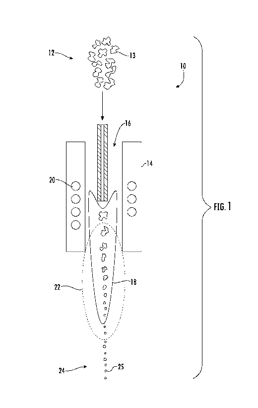
[0020] FIG. 1 shows an exemplary apparatus for plasma spheroidization of a
powder material
improving the properties of a powder material such that the improved powder
material may be more
suitable for additive manufacturing techniques;
[0021] FIG. 2A is a scanning electron microscope (SEM) image of an
exemplary feedstock
powder according to Example;
[0022] FIG. 2B is a magnified SEM image of the exemplary feedstock powder
of FIG. 2A;
[0023] FIG. 3A is a SEM image of an exemplary spheroidized powder formed
from the
feedstock powder shown in FIGs. 2A and 2B prior to washing according to
Example;
[0024] FIG. 3B is a magnified SEM image of the exemplary spheroidized
powder of FIG. 3A;
[0025] FIG. 4A is a SEM image of the exemplary spheroidized powder shown in
FIGs. 3A and
3B after washing according to the Example; and
[0026] FIG. 4B is a magnified SEM image of the exemplary washed,
spheroidized powder of
FIG. 4A.
[0027] Repeat use of reference characters in the present specification and
drawings is intended to
represent the same or analogous features or elements of the present invention.
DETAILED DESCRIPTION OF PARTICULAR EMBODIMENTS
[0028] Reference now will be made in detail to embodiments of the
invention, one or more
examples of which are illustrated in the drawings. Each example is provided by
way of explanation
of the invention, not limitation of the invention. In fact, it will be
apparent to those skilled in the art
that various modifications and variations can be made in the present invention
without departing
from the scope or spirit of the invention. For instance, features illustrated
or described as part of one
embodiment can be used with another embodiment to yield a still further
embodiment. Thus, it is
intended that the present invention covers such modifications and variations
as come within the
scope of the appended claims and their equivalents.
4
CA 03071833 2020-01-31
WO 2019/045923 PCT/US2018/044089
[0029] As used herein, the terms "first", "second", and "third" may be used
interchangeably to
distinguish one component from another and are not intended to signify
location or importance of the
individual components.
[0030] The terms "upstream" and "downstream" refer to the relative
direction with respect to
fluid flow in a fluid pathway. For example, "upstream" refers to the direction
from which the fluid
flows, and "downstream" refers to the direction to which the fluid flows.
[0031] Methods are generally provided for creating higher quality powder
materials (i.e., a
treated powder) from a lower-quality powder source (i.e., a feedstock powder),
along with apparatus
to perform such methods and the resulting particles. In one embodiment, a
powder formed from
water atomization techniques and having irregular shapes (such as formed from
water atomization
techniques) is transformed into a higher quality powder. In one embodiment,
treated particles of the
treated powder may have a more spherical shape than the feedstock particles of
the feedstock
powder, which may be irregular, non-spherical in shape. Additionally, any
oxidation layer present
on the feedstock powder may be removed (e.g., through chemical reduction). In
one embodiment,
the treated powder may be substantially free from any oxidation layer on its
surface. As used herein,
the term "substantially free" means no more than an insignificant trace amount
present and
encompasses completely free (e.g., 0 molar % up to 0.01 molar %).
[0032] In one embodiment, the treated powder is subjected to (e.g., exposed
to) plasma
spheroidization to produce the high quality powder. Referring to Fig. 1, a
diagram of a plasma
spheroidization apparatus 10 is generally shown. The feedstock powder 12
(composed of a plurality
of feedstock particles 13) is generally introduced into a plasma chamber 14,
along with a working
gas 16 (also referred to as the plasma gas, no matter its state of matter). A
plasma field 18 may be
formed within the plasma chamber 14 through heating to a temperature
sufficient to convert the
plasma gas 16 from its gaseous state into its plasma state. For example,
heating elements 20 may be
included within the plasma chamber 14, such as an induction coil.
[0033] As stated above, the feedstock particles 13 may have an irregular
shape (e.g., non-
spherical) when introduced into the plasma chamber 14. In certain embodiments,
the feedstock
particles 13 have a maximum size of about 150 micrometers (.ull). For example,
the feedstock
particles 13 may have an average size of about 10 p.m to about 150 p.m (e.g.,
about 50 p.m to about
100 p.m).
[0034] Generally, the feedstock powder 12 may be any metal material. In one
embodiment, the
metal material may include, but is not limited to, pure metals, iron alloys,
aluminum alloys, nickel
alloys, chrome alloys, nickel-based superalloys, cobalt-based superalloys,
iron-based superalloys, or
mixtures thereof. In particular embodiments, alloying elements may be mixed
with the feedstock
CA 03071833 2020-01-31
WO 2019/045923 PCT/US2018/044089
powder 12 prior to or during exposure to the plasma gas 16. As such, the
chemical composition of
the resulting treated powder may be controlled. For example, in one particular
embodiment, carbon
particles may be mixed with the feedstock particles within the plasma field.
[0035] As the feedstock powder 12 is passed through the plasma field 18
that includes the
plasma gas 16 in its plasma state, the surface of the feedstock particles 13
melts or evaporates within
a melting zone 22 that includes the plasma field 18. However, without wishing
to be bound by any
particular theory, it is believed that the feedstock particles 13 do not
entirely melt and/or evaporate,
but rather that the surfaces of the feedstock particles 13 are melted/softened
so as to reshape into a
more regular shape (e.g., more spherical) while having a smaller size. Thus,
at least a portion of the
surface of the feedstock particles 13 are melted/softened within the melting
zone 22.
[0036] In one embodiment, the working gas 16 (i.e., the plasma gas)
includes a reducing gas,
such as hydrogen, carbon monoxide, or a mixture thereof. The reducing gas may
react with any
oxide layer on the surface of the feedstock particles 13, which may be in the
form of chromium
oxide, iron oxide, etc. Such a reducing gas may react with the oxide to remove
it from the surface
such that the resulting treated powder 24 (in the form of a plurality of the
resulting treated particles
25) are substantially free from any oxide layer thereon. Thus, in one
particular embodiment, the
reducing component reduces any oxide layer on the surface of the feedstock
particles such that the
resulting treated particles are substantially free from any oxide layer
thereon.
[0037] Through this plasma spheroidization process, the size of the
feedstock particles 13 may be
decreased such that the resulting treated particles 25 have an average
particle size that is less than an
average particle size of the feedstock particles 13. In one embodiment, the
resulting treated particles
25 have an average particle size that is about 10% to about 90% of the average
particle size of the
feedstock particles 13. In certain embodiments, the treated particles 25 have
a maximum size of
about 150 p.m (e.g., an average size of about 10 p.m to about 150 p.m). In
particular embodiments,
the treated particles 25 have a maximum size of about 50 p.m (e.g., an average
size of about 10 p.m to
about 50 p.m).
[0038] Such a technique can be used to recondition powders as well.
[0039] As stated, the plasma spheroidization of the feedstock powder 12
improves the properties
of the feedstock powders 12 such that the improved powder material (i.e., the
treated powder 24)
may be more suitable for additive manufacturing techniques. As used herein,
the terms "additively
manufactured" or "additive manufacturing techniques or processes" refer
generally to manufacturing
processes wherein successive layers of material(s) are provided on each other
to "build-up," layer-
by-layer, a three-dimensional component. The successive layers generally fuse
together to form a
monolithic component which may have a variety of integral sub-components.
Although additive
6
CA 03071833 2020-01-31
WO 2019/045923 PCT/US2018/044089
manufacturing technology is described herein as enabling fabrication of
complex objects by building
objects point-by-point, layer-by-layer, typically in a vertical direction,
other methods of fabrication
are possible and within the scope of the present subject matter. For example,
although the discussion
herein refers to the addition of material to form successive layers, one
skilled in the art will
appreciate that the methods and structures disclosed herein may be practiced
with any additive
manufacturing technique or manufacturing technology. For example, embodiments
of the present
invention may use layer-additive processes, layer-subtractive processes, or
hybrid processes.
[0040] Suitable additive manufacturing techniques in accordance with the
present disclosure
include, for example, Fused Deposition Modeling (FDM), Selective Laser
Sintering (SLS), 3D
printing such as by inkjets, laser jets, and binder jets, Sterolithography
(SLA), Direct Selective Laser
Sintering (DSLS), Electron Beam Sintering (EBS), Electron Beam Melting (EBM),
Laser
Engineered Net Shaping (LENS), Laser Net Shape Manufacturing (LNSM), Direct
Metal Deposition
(DMD), Digital Light Processing (DLP), Direct Selective Laser Melting (DSLM),
Selective Laser
Melting (SLM), Direct Metal Laser Melting (DMLM), and other known processes.
[0041] The additive manufacturing processes described herein may be used
for forming
components using any suitable material. For example, the material may be
plastic, metal, concrete,
ceramic, polymer, epoxy, photopolymer resin, or any other suitable material
that may be in solid,
liquid, powder, sheet material, wire, or any other suitable form or
combinations thereof. More
specifically, according to exemplary embodiments of the present subject
matter, the additively
manufactured components described herein may be formed in part, in whole, or
in some combination
of materials including but not limited to pure metals, iron alloys, aluminum
alloys, nickel alloys,
chrome alloys, and nickel-based, iron-based, or cobalt-based superalloys
(e.g., those available under
the name Inconel available from Special Metals Corporation). These materials
are examples of
materials suitable for use in the additive manufacturing processes described
herein, and may be
generally referred to as "additive materials."
[0042] In addition, one skilled in the art will appreciate that a variety
of materials and methods
for bonding those materials may be used and are contemplated as within the
scope of the present
disclosure. As used herein, references to "fusing" may refer to any suitable
process for creating a
bonded layer of any of the above materials. For example, if an object is made
from polymer, fusing
may refer to creating a thermoset bond between polymer materials. If the
object is epoxy, the bond
may be formed by a crosslinking process. If the material is ceramic, the bond
may be formed by a
sintering process. If the material is powdered metal, the bond may be formed
by a melting or
sintering process. One skilled in the art will appreciate that other methods
of fusing materials to
7
CA 03071833 2020-01-31
WO 2019/045923 PCT/US2018/044089
make a component by additive manufacturing are possible, and the presently
disclosed subject matter
may be practiced with those methods.
[0043] In addition, the additive manufacturing process disclosed herein
allows a single
component to be formed from multiple materials. Thus, the components described
herein may be
formed from any suitable mixtures of the above materials. For example, a
component may include
multiple layers, segments, or parts that are formed using different materials,
processes, and/or on
different additive manufacturing machines. In this manner, components may be
constructed which
have different materials and material properties for meeting the demands of
any particular
application. In addition, although the components described herein are
constructed entirely by
additive manufacturing processes, it should be appreciated that in alternate
embodiments, all or a
portion of these components may be formed via casting, machining, and/or any
other suitable
manufacturing process. Indeed, any suitable combination of materials and
manufacturing methods
may be used to form these components.
[0044] An exemplary additive manufacturing process will now be described.
Additive
manufacturing processes fabricate components using three-dimensional (3D)
information, for
example a three-dimensional computer model, of the component. Accordingly, a
three-dimensional
design model of the component may be defined prior to manufacturing. In this
regard, a model or
prototype of the component may be scanned to determine the three-dimensional
information of the
component. As another example, a model of the component may be constructed
using a suitable
computer aided design (CAD) program to define the three-dimensional design
model of the
component.
[0045] The design model may include 3D numeric coordinates of the entire
configuration of the
component including both external and internal surfaces of the component. For
example, the design
model may define the body, the surface, and/or internal passageways such as
openings, support
structures, etc. In one exemplary embodiment, the three-dimensional design
model is converted into
a plurality of slices or segments, e.g., along a central (e.g., vertical) axis
of the component or any
other suitable axis. Each slice may define a thin cross section of the
component for a predetermined
height of the slice. The successive cross-sectional slices together form the
3D component. The
component is then "built-up" slice-by-slice, or layer-by-layer, until
finished.
[0046] In this manner, the components described herein may be fabricated
using the additive
process, or more specifically each layer is successively formed, e.g., by
fusing or polymerizing a
plastic using laser energy or heat or by sintering or melting metal powder.
For example, a particular
type of additive manufacturing process may use an energy beam, for example, an
electron beam or
electromagnetic radiation such as a laser beam, to sinter or melt a powder
material. Any suitable
8
CA 03071833 2020-01-31
WO 2019/045923 PCT/US2018/044089
laser and laser parameters may be used, including considerations with respect
to power, laser beam
spot size, and scanning velocity. The build material may be formed by any
suitable powder or
material selected for enhanced strength, durability, and useful life,
particularly at high temperatures.
[0047] Each successive layer may be, for example, between about 10 [im and
200 [im, although
the thickness may be selected based on any number of parameters and may be any
suitable size
according to alternative embodiments. Therefore, utilizing the additive
formation methods described
above, the components described herein may have cross sections as thin as one
thickness of an
associated powder layer, e.g., 10 [im, utilized during the additive formation
process.
[0048] In addition, utilizing an additive process, the surface finish and
features of the
components may vary as need depending on the application. For example, the
surface finish may be
adjusted (e.g., made smoother or rougher) by selecting appropriate laser scan
parameters (e.g., laser
power, scan speed, laser focal spot size, etc.) during the additive process,
especially in the periphery
of a cross-sectional layer which corresponds to the part surface. For example,
a rougher finish may
be achieved by increasing laser scan speed or decreasing the size of the melt
pool formed, and a
smoother finish may be achieved by decreasing laser scan speed or increasing
the size of the melt
pool formed. The scanning pattern and/or laser power can also be changed to
change the surface
finish in a selected area.
[0049] Notably, in exemplary embodiments, several features of the
components described herein
were previously not possible due to manufacturing restraints. However, the
present inventors have
advantageously utilized current advances in additive manufacturing techniques
to develop exemplary
embodiments of such components generally in accordance with the present
disclosure. While the
present disclosure is not limited to the use of additive manufacturing to form
these components
generally, additive manufacturing does provide a variety of manufacturing
advantages, including
ease of manufacturing, reduced cost, greater accuracy, etc.
[0050] In this regard, utilizing additive manufacturing methods, even multi-
part components may
be formed as a single piece of continuous metal, and may thus include fewer
sub-components and/or
joints compared to prior designs. The integral formation of these multi-part
components through
additive manufacturing may advantageously improve the overall assembly
process. For example, the
integral formation reduces the number of separate parts that must be
assembled, thus reducing
associated time and overall assembly costs. Additionally, existing issues
with, for example, leakage,
joint quality between separate parts, and overall performance may
advantageously be reduced.
[0051] Also, the additive manufacturing methods described above enable much
more complex
and intricate shapes and contours of the components described herein. For
example, such
components may include thin additively manufactured layers and unique fluid
passageways with
9
CA 03071833 2020-01-31
WO 2019/045923 PCT/US2018/044089
integral mounting features. In addition, the additive manufacturing process
enables the manufacture
of a single component having different materials such that different portions
of the component may
exhibit different performance characteristics. The successive, additive nature
of the manufacturing
process enables the construction of these novel features. As a result, the
components described
herein may exhibit improved functionality and reliability.
EXAMPLES
[0052] As an example, water atomized powder was purchased from under their
designation 316
powder, which had the sizing of -325 mesh/15 microns. This water atomized
powder is an iron-based
alloy. The water atomized powder was found to have an apparent density of 2.75
(g/cm3) with an
oxygen content of 0.164% (by wt.), nitrogen content of 0.047% (wt %), and
hydrogen content of
0.001% (by wt. %). The water atomized powder was found to have the particle
size distribution
shown in Table 1 prior to any treatment performed.
Table 1: Volume Statistics (Arithmetic)
Calculations from 0.375 p.m to 2000 p.m
<25% <50% <75% <90%
<10%
15.98 p.m 24.72 34.62 45.18 55.68 p.m
Volume: 100%
Mean: 35.65 p.m SD: 15.95 p.m
Median: 34.62 p.m Variance: 254.4 i.tm2
Mean/Median Ratio: 1.030 C.V.: 44.7%
Mode: 37.97 p.m Skewness: 0.588 right skewed
Kurtosis: 0.773 Leptokurtic
[0053] FIGs. 2A and 2B show SEM images of the water atomized powder prior
to any treatment
performed. As shown, the water atomized powder includes particles of varying
size and shape.
[0054] Then, the water atomized powder was spheroidized using argon as a
primary gas, with
hydrogen as a secondary gas. Other experiments were also performed using
helium and nitrogen as a
secondary gas, with argon being the primary gas. It was found that the
spheroidization resulted in a
more uniform size and shape of the particles in the powder.
[0055] FIGs. 3A and 3B shown images of the spheroidized powder after
spheroidized using
argon as a primary gas and hydrogen as a secondary gas.
CA 03071833 2020-01-31
WO 2019/045923 PCT/US2018/044089
[0056] Then, the spheroidized powder was washed using an industrial washing
unit. FIGs. 4A
and 4B show images of the spheroidized powder. As seen, relatively clean and
uniform particles
make up the powder following this spheroidization and washing process.
[0057] The spheroidized powder was found to have an oxygen content of
0.057% (wt %),
nitrogen content of 0.009% (wt %), and hydrogen content of 0.0007% (wt %).
Thus, the
spheroidized powder had significantly reduced contents of oxygen, nitrogen,
and hydrogen.
[0058] Table 2 shows the particle size distribution after spheroidization
and washing.
Table 2: Volume Statistics (Arithmetic)
Calculations from 0.375 p.m to 2000 p.m
<25% <50% <75% <90%
<10%
19.55 p.m 24.86 30.48 35.97 40.80 p.m
Volume: 100%
Mean: 30.30 p.m SD: 8.014 p.m
Median: 30.48 p.m Variance: 64.23 m2
Mean/Median Ratio: 0.994 C.V.: 26.4%
Mode: 31.51 p.m Skewness: -0.085 left skewed
Kurtosis: -0.347 Platykurtic
[0059] In conclusion, spheroidization of water atomized powder was
successful and overcame
both of the major issues of irregular shape and high oxygen content.
[0060] This written description uses exemplary embodiments to disclose the
invention, including
the best mode, and also to enable any person skilled in the art to practice
the invention, including
making and using any devices or systems and performing any incorporated
methods. The patentable
scope of the invention is defined by the claims, and may include other
examples that occur to those
skilled in the art. Such other examples are intended to be within the scope of
the claims if they
include structural elements that do not differ from the literal language of
the claims, or if they
include equivalent structural elements with insubstantial differences from the
literal languages of the
claims.
11