Note: Descriptions are shown in the official language in which they were submitted.
CA 03072021 2020-02-04
DESCRIPTION
Title of Invention
ELECTROLYTIC DEVICE
Technical Field
[0001]
The present invention relates to an electrolytic apparatus
that generates hydrogen gas by electrolysis.
Background Art
[0002]
In alkaline water electrolysis, electrolysis of unpurified
water, brine electrolysis, electrolysis of chloride aqueous
solution, bromic acid aqueous solution, hydrochloric acid, and
sulfuric acid aqueous solution, etc., hydrogen gas is generated
from a cathode chamber by electrolysis.
An alkaline water electrolytic apparatus and an alkaline
water electrolysis method described in Patent Literature I are
an example of an electrolytic apparatus and an electrolysis
method for generating hydrogen gas. In the electrolytic
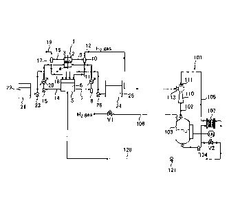
apparatus and the electrolysis method described in Patent
Literature 1, an anolyte and a catholyte including a gas-liquid
mixed fluid produced in an anode chamber and a cathode chamber
are collected in a common circulation tank, mixed in the
circulation tank, and then circulated and supplied to both
electrolytic chambers of the anode chamber and the cathode
chamber. By mixing the anolyte and the catholyte in the
circulation tank, continuous electrolysis is carried out while
maintaining concentrations of electrolytes supplied to both
the electrolytic chambers at the same concentration and
constantly maintaining constant concentration.
[0003]
In recent years, it has become important to escape from
fossil fuels to prevent global warming, and use of hydrogen
gas as an alternative energy source has been widely studied.
For example, as disclosed in Patent Literature 2, high-purity
1
CA 03072021 2020-02-04
hydrogen gas generated by electrolysis is required to be
pressurized by a compressor so that the hydrogen gas is
transferred to a subsequent process such as storage.
[0004]
In alkaline water electrolysis, electrolysis of unpurified
water, brine electrolysis, electrolysis of chloride aqueous
solution, aqueous bromide solution, hydrochloric acid,
sulfuric acid aqueous solution, etc., hydrogen gas is generated
from the cathode chamber and oxygen gas, ozone gas and/or
chlorinegasisgeneratedfromtheanodechamberbyelectrolysis.
Oxygen gas may be discharged into the atmosphere in some cases
or recovered and used for another purpose in some cases. Ozone
gas and chlorine gas are recovered and used.
Citation List
Patent Literature
[0005]
Patent Literature 1: JP 2015-29921 A
Patent Literature 2: JP 2010-143778 A
Summary of Invention
Technical Problem
[0006]
In the above-described conventional electrolytic apparatus,
the compressor is used to pressurize the gas produced under
atmospheric pressure. The compressor includes a turbo
compressor anda volume compressor, both of which are large-sized
devices. Therefore, a large facility area is required,
facility cost is high, and noise is further problematic.
[0007]
In addition, in the above-described conventional
electrolytic apparatus, hydrogen gas and oxygen gas are
separated from an electrolyte by a gas-liquid separator. In
the alkaline water electrolytic apparatus, a mixed alkaline
electrolyte is mixed in the circulation tank, and circulated
and used in the anode chamber and the cathode chamber. Thus,
in this instance, the hydrogen gas and the oxygen gas contain
2
. .
CA 03072021 2020-02-04
impurities such as alkaline mist, particles, etc.
In addition, in the brine electrolysis, the anolyte and
the catholyte are used without being circulated in some cases
and are circulated and used in some cases. In either case,
the electrolyte becomes alkaline and the hydrogen gas generated
in the cathode chamber contains impurities such as alkaline
mist in the cathode chamber, and the electrolyte becomes acidic,
and the oxygen gas generated in the anode chamber contains
impurities such as acid mist in the anode chamber.
Hydrogen gas and oxygen gas separated from the electrolyte
are washed using a water washing tower to remove impurities
such as alkaline mist and acid mist. However, impurities such
as alkaline mist, etc. may be not sufficiently removed by a
simple facility such as the water washing tower, a mist separator,
etc. in a line. For this reason, when aluminum is used for
a part of the compressor, there is a problem that aluminum is
corroded by alkaline mist. In addition, the particles
contained in the gas affect operation of the compressor.
In addition, when removal of alkaline mist and acid mist
in the product gas is insufficient, alkali and acid exceeding
environmental standards may be discharged to the atmosphere.
[0008]
An object of the present invention is to solve these problems
of the conventional technology, and to provide an electrolytic
apparatus capable of pressurizing hydrogen gas produced by the
electrolytic apparatus and removing impurities such as alkaline
mist, etc. in the produced hydrogen gas using an inexpensive
facility having a small installation area.
Solution to Problem
[0009]
To achieve the above object, according to a first solution
of the present invention, there is provided an electrolytic
apparatus including:
an electrolyzer that includes an anode chamber
accommodating an anode, a cathode chamber accommodating a
cathode, and a diaphragm partitioning the anode chamber and
3
CA 03072021 2020-02-04
the cathode chamber;
a cathode side electrolyte discharge line connected to the
cathode chamber to discharge a cathode side electrolyte
containing hydrogen gas from the cathode chamber;
a cathode side gas-liquid separating means connected to
the cathode side electrolyte discharge line to separate the
hydrogen gas from the cathode side electrolyte;
a hydrogen gas discharge line connected to the cathode side
gas-liquid separating means to discharge the hydrogen gas
separated by the cathode side gas-liquid separating means from
the cathode side gas-liquid separating means; and
a gas compression means connected to the hydrogen gas
discharge line, wherein
the gas compression means includes
a cathode side ejector connected to the hydrogen gas
discharge line,
a cathode side storage tank that stores the hydrogen gas
and a cathode side circulation liquid flowing in the gas
compression means,
a cathode side fluid mixture feed pipe that connects the
cathode side ejector and the cathode side storage tank to each
other, and feeds a fluid mixture of the cathode side circulation
liquid and the hydrogen gas from the cathode side ejector to
the cathode side storage tank,
a cathode side circulation pipe that connects the cathode
side storage tank and the cathode side ejector to each other,
and feeds the cathode side circulation liquid from the cathode
side storage tank to the cathode side ejector,
a cathode side circulation pump installed in the cathode
side circulation pipe,
a hydrogen gas discharge pipe connected to the cathode side
storage tank to discharge the hydrogen gas from the cathode
side storage tank, and
a first valve provided in the hydrogen gas discharge pipe,
the hydrogen gas is allowed to flow into the cathode side
ejector from the hydrogen gas discharge line by circulating
the cathode side circulation liquid from the cathode side storage
4
CA 03072021 2020-02-04
tank to the cathode side ejector using the cathode side
circulation pump, the cathode side fluid mixture feed pipe,
and the cathode side circulation pipe, the hydrogen gas and
the cathode side circulation liquid are mixed in the cathode
side ejector, and an impurity in the hydrogen gas is transferred
to the cathode side circulation liquid to remove the impurity
from the hydrogen gas, and
a pressure of the hydrogen gas stored in the cathode side
storage tank is raised by controlling a flow rate of the cathode
side circulation liquid circulated from the cathode side storage
tank to the cathode side ejector and opening and closing of
the first valve.
[0010]
To achieve the above object, according to a second solution
of the present invention, there is provided the electrolytic
apparatus, further including:
an anode side electrolyte discharge line connected to the
anode chamber to discharge an anode side electrolyte containing
anode gas from the anode chamber;
anode side gas-liquid separating means connected to the
anode side electrolyte discharge line to separate the anode
gas from the anode side electrolyte;
an anode gas discharge line connected to the anode side
gas-liquid separating means to discharge the anode gas separated
by the anode side gas-liquid separating means from the anode
side gas-liquid separating means; and
impurity removal means connected to the anode gas discharge
line, wherein
the impurity removal means includes
an anode side ejector connected to the anode gas discharge
line,
an anode side storage tank that stores the anode gas and
an anode side circulation liquid flowing in the impurity removal
means,
an anode side fluid mixture feed pipe that connects the
anode side ejector and the anode side storage tank to each other,
and feeds a fluid mixture of the anode side circulation liquid
. .
CA 03072021 2020-02-04
and the anode gas from the anode side ejector to the anode side
storage tank,
an anode side circulation pipe that connects the anode side
storage tank and the anode side ejector to each other, and feeds
the anode side circulation liquid from the anode side storage
tank to the anode side ejector, and
an anode side circulation pump installed in the anode side
circulation pipe, and
the anode gas is allowed to flow into the anode side ejector
from the anode gas discharge line by circulating the anode side
circulation liquid from the anode side storage tank to the anode
side ejector using the anode side circulation pump, the anode
side fluid mixture feed pipe, and the anode side circulation
pipe, the anode gas and the anode side circulation liquid are
mixed in the anode side ejector, and an impurity in the anode
gas is transferred to the anode side circulation liquid to remove
the impurity in the anode gas.
[0011]
To achieve the above object, according to a third solution
of the present invention, there is provided the electrolytic
apparatus, wherein
the impurity removal means further includes
an anode gas discharge pipe connected to the anode side
storage tank to discharge the anode gas from the anode side
storage tank, and
a second valve provided in the anode gas discharge pipe,
and
a pressure of the anode gas stored in the anode side storage
tank is raised by controlling a flow rate of the anode side
circulation liquid circulated from the anode side storage tank
to the anode side ejector and opening and closing of the second
valve.
[0012]
To achieve the above object, according to a fourth solution
of the present invention, there is provided the electrolytic
apparatus, wherein the cathode side electrolyte corresponds
to an alkaline aqueous solution, and the impurity in the hydrogen
6
CA 03072021 2020-02-04
gas contains alkaline mist.
[0013]
To achieve the above object, according to a fifth solution
of the present invention, there is provided the electrolytic
apparatus, wherein the anode side electrolyte corresponds to
an alkaline aqueous solution, and the impurity in the anode
gas contains alkaline mist.
[0014]
To achieve the above object, according to a sixth solution
of the present invention, there is provided the electrolytic
apparatus, wherein the anode side electrolyte corresponds to
a chloride aqueous solution, and the impurity in the anode gas
contains acid mist.
[0015]
To achieve the above object, according to a seventh solution
of the present invention, there is provided the electrolytic
apparatus, wherein the anode side electrolyte corresponds to
hydrochloric acid, and the impurity in the anode gas contains
acid mist.
[0016]
To achieve the above object, according to an eighth solution
of the present invention, there is provided the electrolytic
apparatus, wherein the anode side electrolyte corresponds to
a bromic acid aqueous solution, and the impurity in the anode
gas contains acid mist.
[0017]
To achieve the above object, according to a ninth solution
of the present invention, there is provided the electrolytic
apparatus, wherein the anode side electrolyte corresponds to
a sulfuric acid aqueous solution, and the impurity in the anode
gas contains acid mist.
Advantageous Effects of Invention
[0018]
According to the present invention, it is possible to
pressurize hydrogen gas using an inexpensive facility having
a small installation area when compared to gas compression using
7
. .
CA 03072021 2020-02-04
a conventional compressor, and to remove impurities such as
alkaline mist and particles contained in the hydrogen gas.
Similarly on an anode side, it is possible to remove
impurities contained in anode gas using an inexpensive facility
having a small installation area. For example, even when oxygen
gas generated by electrolysis is released into the atmosphere,
it is possible to suppress release of the alkaline mist, acid
mist, and particles into the environment. Furthermore, it is
possible to pressurize the anode gas using a simple facility.
In addition, according to the present invention, since it
is unnecessary to use a conventional large-sized compressor,
it is possible to reduce the volume of the facility. Further,
there is no vibration, noise, and mechanical damage during a
long-term operation and stable operation is allowed for a long
period of time. Furthermore, a maintenance cost of an apparatus
is greatly reduced.
Brief Description of Drawings
[0019]
Fig. 1 is a flow diagram illustrating an alkaline water
electrolytic apparatus according to a first embodiment of the
present invention.
Fig. 2 is a cross-sectional view illustrating details of
an example of an ejector used for the alkaline water electrolytic
apparatus according to the first embodiment of the present
invention.
Fig. 3 is a flow diagram illustrating a part (impurity
removal means) of an alkaline water electrolytic apparatus
according to another embodiment of the present invention.
Description of Embodiments
[0020]
(First Embodiment)
Fig. 1 is a flow diagram illustrating an example of an
electrolytic apparatus according to a first embodiment of the
present invention. Here, an alkaline water electrolysis
apparatus will be described as an example. However, the present
8
CA 03072021 2020-02-04
invention is applicable to an electrolytic apparatus that
generates hydrogen gas by electrolysis such as electrolysis
of unpurified water, brine electrolysis, electrolysis of
chloride aqueous solution, aqueous bromide solution,
hydrochloric acid, sulfuric acid aqueous solution, etc. in
addition to alkaline water electrolysis.
In Fig. 1, the alkaline water electrolytic apparatus has
an electrolyzer 1. Reference numeral 2 denotes a cathode
chamber accommodating a cathode, reference numeral 3 denotes
an anode chamber accommodating an anode, and reference numeral
4 denotes a diaphragm partitioning the cathode chamber 2 and
the anode chamber 3. The diaphragm 4 corresponds to a composite
membrane including a cation exchange membrane, an anion exchange
membrane, a polymer porous layer, and a nonwoven fabric, etc.
[0021]
Cathode side electrolyte circulating means and cathode gas
separating means are provided as a cathode side electrolyte
feed path. The cathode gas separating means includes a cathode
side electrolyte discharge line 9, cathode side gas-liquid
separating means 10, and a hydrogen gas discharge line 12. The
cathode side electrolyte circulating means includes a
circulation tank 5, a cathode side electrolyte supply line 7,
a circulation pump 8, and a cathode side electrolyte recovery
line 11.
The cathode side electrolyte supply line 7 is a pipe that
connects the cathode chamber 2 and the circulation tank 5 to
each other and supplies an electrolyte 6 stored in the
circulation tank 5 to the cathode chamber 2 using the circulation
pump 8. The cathode side electrolyte discharge line 9 is a
pipe that connects the cathode chamber 2 and the cathode side
gas-liquid separating means 10 to each other and feeds an
electrolyte (cathode side electrolyte) and hydrogen gas in the
cathode chamber 2 to the cathode side gas-liquid separating
means 10. The cathode side gas-liquid separating means 10
separates hydrogen gas from the electrolyte. The cathode side
electrolyte recovery line 11 is a pipe that connects the cathode
side gas-liquid separating means 10 and the circulation tank
9
. .
CA 03072021 2020-02-04
to each other and feeds the electrolyte separated by the cathode
side gas-liquid separating means 10 to the circulation tank
5. The hydrogen gas discharge line 12 is a pipe that connects
the cathode side gas-liquid separating means 10 and gas
compression means 101 described below to each other and feeds
hydrogen gas separated by the cathode side gas-liquid separating
means 10 to the gas compression means 101. A heat exchanger
13 is installed in the cathode side electrolyte supply line
7.
[0022]
Anode side electrolyte circulating means and anode gas
separating means are provided as an anode side electrolyte feed
path. The anode gas separating means includes an anode side
electrolyte discharge line 16, an anode side gas-liquid
separating means 17, and an anode gas discharge line 19. The
anode side electrolyte circulating means includes the
circulation tank 5, an anode side electrolyte supply line 14,
a circulation pump 15, and an anode side electrolyte recovery
line 18.
The anode side electrolyte supply line 14 is a pipe that
connects the anode chamber 3 and the circulation tank 5 to each
other and supplies the electrolyte 6 stored in the circulation
tank 5 to the anode chamber 3 using the circulation pump 15.
The anode side electrolyte discharge line 16 is a pipe that
connects the anode chamber 3 and the anode side gas-liquid
separating means 17 to each other and feeds an electrolyte (anode
side electrolyte) and anode gas (oxygen gas in the case of
alkaline water electrolysis) in the anode chamber 3 to the anode
side gas-liquid separating means 17. The anode side gas-liquid
separating means 17 separates anode gas from the electrolyte.
The anode side electrolyte recovery line 18 is a pipe that
connects the anode side gas-liquid separating means 17 and the
circulation tank 5 to each other and feeds the electrolyte
separated by the anode side gas-liquid separating means 17 to
the circulation tank 5. The anode gas discharge line 19 is
a pipe connected to the anode side gas-liquid separating means
17 to discharge the anode gas separated by the anode side
CA 03072021 2020-02-04
gas-liquid separating means 17 to an outside of a system. A
heat exchanger 20 is installed in the anode side electrolyte
supply line 14.
[0023]
In the example of Fig. 1, the electrolyte corresponds to
an alkaline aqueous solution (for example, an aqueous solution
of an alkali metal hydroxide, specifically, a KOH aqueous
solution or a NaOH aqueous solution) .
[0024]
The electrolytic apparatus of the present embodiment
includes electrolyte replenishing means and water replenishing
means. The electrolyte replenishing means includes an alkaline
water tank 21 that stores high-concentration alkaline water
22 and a pump 23. The water replenishing means includes a pure
water tank 24 that stores pure water 25 and a pump 26.
[0025]
In the alkaline water electrolytic apparatus, as
illustrated in Fig. 1, the circulation tank is common between
an anode side and a cathode side. Therefore, in the cathode
side electrolyte circulating means and the anode side
electrolyte circulating means, an electrolyte in which the anode
side electrolyte and the cathode side electrolyte are mixed
circulates between the cathode chamber 2 and the circulation
tank 5 and between the anode chamber 3 and the circulation tank
5.
[0026]
The gas compression means 101 is provided on a downstream
side of the hydrogen gas discharge line 12. The gas compression
means 101 includes a cathode side ejector 110, a cathode side
fluid mixture feed pipe 102, a cathode side storage tank 103,
a cathode side circulation pump 104, a cathode side circulation
pipe 105, and a hydrogen gas discharge pipe 106.
[0027]
Fig. 2 is a cross-sectional view illustrating details of
an example of the cathode side ejector 110. Reference numeral
111 denotes a nozzle, reference numeral 112 denotes a diffuser,
reference numeral 113 denotes a suction port, and reference
11
CA 03072021 2020-02-04
numeral 114 denotes a suction chamber. The nozzle 111 is
connected to the circulation pipe 105. The suction port 113
is connected to the hydrogen gas discharge line 12. An outlet
112a of the diffuser 112 is connected to the cathode side fluid
mixture feed pipe 102.
[0028]
The cathode side fluid mixture feed pipe 102 connects the
cathode side ejector 110 and the cathode side storage tank 103
to each other and feeds a fluid mixture discharged from the
cathode side ejector 110 to the cathode side storage tank 103.
[0029]
The cathode side storage tank 103 accommodates a circulation
liquid (cathode side circulation liquid) therein. This
circulation liquid corresponds to water and contains impurities
(described below) contained in the hydrogen gas. Hydrogen gas
separated from the fluid mixture fed from the cathode side
ejector 110 is stored in an upper space of the cathode side
storage tank 103. The cathode side circulation pipe 105 is
connected to a bottom portion of the cathode side storage tank
103. The hydrogen gas discharge pipe 106 is connected to an
upper portion of the cathode side storage tank 103. A valve
V1 (first valve) is installed in the hydrogen gas discharge
pipe 106.
[0030]
The cathode side circulation pump 104 and a cathode side
heat exchanger 107 are installed in the cathode side circulation
pipe 105. The circulation liquid in the cathode side storage
tank 103 is circulated to the cathode side ejector 110 through
the cathode side circulation pipe 105 by the cathode side
circulation pump 104.
[0031]
In the electrolytic apparatus of the present embodiment,
a cathode side circulation liquid ejection pipe 120 may be
connected to the cathode side circulation pipe 105. A valve
V2 and a pump 121 are installed in the cathode side circulation
liquid ejection pipe 120. The cathode side circulation liquid
ejection pipe 120 may be configured to discharge a part of the
12
CA 03072021 2020-02-04
circulation liquid to the outside of the system or may be
configured to. circulate a part of the circulation liquid to
the electrolyte. As a configuration for using the circulation
liquid as the electrolyte, the cathode side circulation liquid
ejection pipe 120 is connected to any one of the cathode side
electrolyte feed path and the anode side electrolyte feed path.
In this example of Fig. 1, the cathode side circulation liquid
ejection pipe 120 is connected to the circulation tank 5.
Alternatively, the cathode side circulation liquid ejection
pipe 120 may be connected to any one of the cathode side
electrolyte supply line 7, the cathode side electrolyte
discharge line 9, the cathode side electrolyte recovery line
11, the anode side electrolyte supply line 14, the anode side
electrolyte discharge line 16, and the anode side electrolyte
recovery line 18.
[0032]
Hereinafter, a description will be given of a process of
performing electrolysis and compression of hydrogen gas using
the electrolytic apparatus of Fig. 1.
Before a start and in an initial period of electrolysis,
the electrolyte replenishing means supplies the alkaline water
22 from the alkaline water tank 21 to the circulation tank 5
using the pump 23. The water replenishing means supplies the
pure water 25 from the pure water tank 24 to the circulation
tank 5 using the pump 26. The alkaline water and the pure water
are mixed in the circulation tank 5, and the electrolyte 6 is
adjusted to a predetermined concentration. Together with the
pure water 25, new raw material water for electrolysis may be
added into the circulation tank 5.
[0033]
The electrolyte 6 is supplied to the cathode chamber 2 of
the electrolyzer 1 through the cathode side electrolyte supply
line 7 by the circulation pump 8. The electrolyte is cooled
to a predetermined temperature by passing through the heat
exchanger 13. In addition, the electrolyte 6 is supplied to
the anode chamber 3 of the electrolyzer 1 through the anode
side electrolyte supply line 14 by the circulation pump 15.
13
CA 03072021 2020-02-04
The electrolyte is cooled or heated to a predetermined
temperature by passing through the heat exchanger 20.
[0034]
The electrolyte is electrolyzed in the cathode chamber 2
and the anode chamber 3. In this way, hydrogen gas is generated
in the cathode chamber 2, and anode gas (oxygen gas) is generated
in the anode chamber 3.
[0035]
The generated hydrogen gas is fed to the cathode side
gas-liquid separating means 10 through the cathode side
electrolyte discharge line 9 together with the electrolyte.
The hydrogen gas and the electrolyte are gas-liquid separated
by the cathode side gas-liquid separating means 10. The
separated electrolyte is circulated through the cathode side
electrolyte recovery line 11 to the circulation tank 5. The
separated hydrogen gas is fed to the gas compression means 101
through the hydrogen gas discharge line 12.
[0036]
The generated oxygen gas is fed to the anode side gas-liquid
separating means 17 through the anode side electrolyte discharge
line 16 together with the electrolyte. The oxygen gas and the
electrolyte are gas-liquid separated by the anode side
gas-liquid separating means 17. The separated electrolyte is
circulated through the anode side electrolyte recovery line
18 to the circulation tank 5. The oxygen gas is discharged
to the outside of the system through the anode gas discharge
line 19.
[0037]
To control the alkali concentration in the cathode chamber
2 and the anode chamber 3, the amount of water corresponding
to water disappearing by electrolysis is supplied from pure
water replenishing means. When pure water is continuously
supplied, electrolysis is continued while an electrolysis
condition such as the concentration of the electrolyte is
maintained at a constant level. The pure water can be
intermittently supplied depending on the volume of the
circulation tank.
14
CA 03072021 2020-02-04
[0038]
In the gas compression means 101, when the cathode side
circulation pump 104 operates, the circulation liquid
circulates through the cathode side fluid mixture feed pipe
102 and the cathode side circulation pipe 105. In the cathode
side ejector 110, the circulation liquid flows from the nozzle
111 toward the diffuser 112. In this way, the hydrogen gas
discharged from the hydrogen gas discharge line 12 is drawn
into the suction chamber 114 from the suction port 113. The
circulation liquid and the hydrogen gas are intensely mixed
in the suction chamber 114, and the fluid mixture is discharged
from the diffuser 112.
[0039]
The fluid mixture is jetted from the cathode side fluid
mixture feed pipe 102 into the cathode side storage tank 103.
The circulation liquid (water) and the hydrogen gas are intensely
mixed in the cathode side ejector 110, and the hydrogen gas
and the circulation liquid are separated from each other in
the cathode side storage tank 103. In this way, impurities
such as alkaline mist (mist of alkaline aqueous solution) and
particles contained in the hydrogen gas flowing through the
hydrogen gas discharge line 12 are transferred to the circulation
liquid, and the hydrogen gas and the impurities are separated
from each other.
[0040]
Further, when a packed tower (not illustrated) filled with
a packing material is provided between the cathode side ejector
110 illustrated in Fig. 2 and the cathode side storage tank
103, a gas-liquid contact area between the hydrogen gas and
a cathode side circulation liquid increases, and collision
between the hydrogen gas and the cathode side circulation liquid
is intense when the hydrogen gas and the cathode side circulation
liquid pass through the packed tower. Thus, a rate of removal
of impurities from the hydrogen gas increases. A plastic
packing material, a metal wire structure packing material, etc.
obtained by molding polypropylene resin, polyethylene resin,
fluororesin, etc. into various sizes may be used as the packing
CA 03072021 2020-02-04
material. Tellerette (Tellerette is a registered trademark
of Tsukishima Kankyo Engineering Ltd.) is an example of the
plastic packing material, and Raschig ring super link (Raschig
ring super link is a registered trademark of Raschig company
(Germany) ) is an example of the metal wire structure packing
material.
The packed tower is preferably provided outside the cathode
side ejector 110. However, the packed tower may be provided
inside the outlet 112a of the diffuser 112 of the cathode side
ejector 110. Alternatively, instead of the packed tower, only
the packing material filled in the inside thereof may be provided
inside the outlet 112a of the diffuser 112.
[0041]
The circulation liquid containing impurities stored in the
cathode side storage tank 103 is circulated to the cathode side
ejector 110 through the cathode side circulation pipe 105 by
the cathode side circulation pump 104. During this process,
the circulation liquid is cooled or heated by the cathode side
heat exchanger 107.
[0042]
The hydrogen gas stored in the cathode side storage tank
103 is pressurized by controlling a circulation speed (flow
rate) of the cathode side circulation liquid circulating from
the cathode side storage tank 103 to the cathode side ejector
110 and opening and closing of the valve Vi. For example, when
the operation of the electrolytic apparatus is started, the
valve VI is closed and the inside of the gas compression means
101 is set to a closed loop. When the flow rate of the cathode
side circulation liquid is increased in this state, the hydrogen
gas is stored in the cathode side storage tank 103 in a pressurized
state. When the hydrogen gas rises to a predetermined pressure,
the valve V1 is opened and a steady operation is performed.
As the flow rate of the cathode side circulation liquid
is increased, a suction force of the cathode side ejector 110
increases. As a result, the amount of hydrogen gas flowing
into the gas compression means 101 increases and the pressure
of hydrogen gas rises. In the present invention, hydrogen gas
16
CA 03072021 2020-02-04
is pressurized up to 1 MPa (10 bar) . For example, when the
circulation speed of the cathode side circulation liquid is
increased to 150 m3/h, the hydrogen gas stored in the cathode
side storage tank 103 is pressurized to 0.6 MPa (6 bar) to 1
MPa (10 bar) .
[0043]
In general, a function of an ejector is to cause a fluid
having a high speed to flow, thereby sucking gas or liquid in
accordance with a flow of the fluid. In this invention, hydrogen
gas is sucked into the cathode side ejector 110 through the
hydrogen gas discharge line 12 by causing the cathode side
circulation liquid to flow to the cathode side ejector 110.
In the cathode side ejector 110, the hydrogen gas and the
circulation liquid intensely collide with each other in a narrow
pipe.
In this phenomenon, to attain a high pressure, a possibility
that the alkaline mist corresponding to an impurity in the
hydrogen gas will further collide with water corresponding to
a circulation liquid and be dissolved in the water corresponding
to circulation liquid increases.
[0044]
In the present invention, the pressure of the hydrogen gas
may be controlled by controlling the circulation speed of the
cathode side circulation liquid from the cathode side storage
tank 103 to the cathode side ejector 110 and opening and closing
of the valve Vi. A high pressure facility is unnecessary since
the hydrogen gas is pressurized up to 1 MPa (10 bar) by the
gas compression means 101 of the present invention. For this
reason, the facility may be simplified and maintenance is
facilitated.
Since it is unnecessary to use a large-sized compressor
in the gas compression means 101 of the present invention, the
installation area can be greatly reduced. In addition, it is
unnecessary to install cooling auxiliaries, etc. of the
compressor. Since the cathode side ejector 110 according to
the present invention does not have a driving unit, there is
no vibration, noise, and mechanical damage during a long-term
17
CA 03072021 2020-02-04
operation and stable use is allowed for a long period of time.
As a result, a maintenance cost of the apparatus is greatly
reduced.
[0045]
On the other hand, in conventional washing using a water
washing tower, for example, a feed rate of washing water is
m3/h with respect to a hydrogen generation amount of 100 Nm3/h.
Considering from a ratio of the washing water to the hydrogen
generation amount to be processed, impurity removal efficiency
is low in the washing using the waterwashing tower . Inaddition,
in the washing using the water washing tower, pressurization
of hydrogen gas is not performed.
[0046]
The pressurized hydrogen gas from which impurities are
removed is discharged to the outside the system of the
electrolytic apparatus through the hydrogen gas discharge pipe
106. The discharged hydrogen gas is stored in, for example,
a tank and then used for another use (such as a fuel cell).
In a case of producing higher pressure hydrogen gas, it is
advantageous to use hydrogen gas compressed using the
electrolytic apparatus of the present invention since energy
can be reduced when compared to a case of pressurizing from
atmospheric pressure.
[0047]
When the circulation liquid is circulated in the gas
compression means 101, the alkaline mist is dissolved in the
circulation liquid, and pH of the circulation liquid rises.
Means (not illustrated in Fig. 1) for measuring the pH of the
circulation liquid is installed in the system of the gas
compressionmeans 101 and linkedwith the valve V2. For example,
the pH measuring means is installed in the cathode side storage
tank 103 or the circulation pipe 105. When the pH of the
circulation liquid reaches a predetermined value, the valve
V2 is opened. Due to the opening of the valve V2, a part of
the circulation liquid flows through the cathode side
circulation liquid ejection pipe 120.
The cathode side circulation liquid may be discharged to
18
CA 03072021 2020-02-04
the outside of the system through the circulation liquid ejection
pipe 120. Alternatively, the cathode side circulation liquid
maybe added to the electrolyte at anyplace of the electrolyte
feed path on the cathode side and the electrolyte feed path
on the anode side through the cathode side circulation liquid
ejection pipe 120, and used as the electrolyte. For example,
in the alkaline water electrolytic apparatus illustrated in
Fig. 1, the cathode side circulation liquid discharged from
the gas compression means 101 is supplied to the circulation
tank 5 through the cathode side circulation liquid ejection
pipe 120 and mixed with the electrolyte.
[0048]
(Second Embodiment)
Fig. 3 is an example of an electrolytic apparatus according
to a second embodiment of the present invention, and is a flow
diagram illustrating impurity removal means corresponding to
a part of the electrolytic apparatus. In this embodiment, an
alkaline water electrolytic apparatus will be described as an
example.
[0049]
The electrolytic apparatus of the second embodiment is an
example in which impurity removal means 201 is further provided
on a downstream side of the anode gas discharge line 19 of the
electrolytic apparatus according to the first embodiment
illustrated in Fig. 1. A configuration of the impurity removal
means 201 is basically the same as that of the gas compression
means 101. That is, the impurity removal means 201 includes
an anode side ejector 210, an anode side fluid mixture feed
pipe 202, an anode side storage tank 203, an anode side
circulation pump 204, an anode side circulation pipe 205, and
an anode gas discharge pipe 206. A valve V3 (second valve)
is installed in the anode gas discharge pipe 206.
[0050]
The anode side ejector 210 has the same configuration as
that of the cathode side ejector 110 described in the first
embodiment. A nozzle 211 of the anode side ejector 210 is
connected to the anode side circulation pipe 205. A suction
19
CA 03072021 2020-02-04
port 213 of the anode side ejector 210 is connected to the anode
gas discharge line 19. A diffuser outlet of the anode side
ejector 210 is connected to the anode side storage tank 203
through the anode side fluid mixture feed pipe 202.
Further, in the anode side ejector 210, when a packed tower
(not illustrated) filled with a packing material is provided
between the anode side ejector 210 and the anode side storage
tank 203, a gas-liquid contact area between anode gas and an
anode side circulation liquid increases, and collision between
the anode gas and the anode side circulation liquid is intense
when the anode gas and the anode side circulation liquid pass
through the packed tower. Thus, a rate of removal of impurities
from the anode gas increases.
The packed tower is preferably provided outside the anode
side ejector 210. However, the packed tower may be provided
inside the diffuser outlet of the anode side ejector 210.
Alternatively, instead of the packed tower, only the packing
material filled in the inside thereof may be provided inside
the diffuser outlet.
[0051]
The anode side circulation pump 204 and an anode side heat
exchanger 207 are installed in the anode side circulation pipe
205. A circulation liquid (water) in the anode side storage
tank 203 is circulated to the anode side ejector 210 through
the anode side circulation pipe 205 and the nozzle 211 by the
anode side circulation pump 204.
[0052]
On the anode side, an anode side circulation liquid ejection
pipe 220 may be connected to the anode side circulation pipe
205. The anode side circulation liquid ejection pipe 220 may
be configured to discharge the circulation liquid to the outside
of the system using the anode side circulation liquid ejection
pipe 220. Alternatively, the anode side circulation liquid
ejection pipe 220 may be configured to be connected to any one
of an electrolyte feed path on a cathode side and an electrolyte
feed path on an anode side, and a part of the circulation liquid
may be added to an electrolyte. Specifically, the anode side
CA 03072021 2020-02-04
circulation liquid ejection pipe 220 may be connected to any
one of the circulation tank 5, the cathode side electrolyte
supply line 7, the cathode side electrolyte discharge line 9,
the cathode side electrolyte recovery line 11, the anode side
electrolyte supply line 14, the anode side electrolyte discharge
line 16, and the anode side electrolyte recovery line 18. A
fourth valve V4 and a pump 221 are installed in the anode side
circulation liquid ejection pipe 220.
[0053]
A process of removing impurities and compressing the anode
gas using the impurity removal means illustrated in Fig. 3 will
be described below.
In the impurity removal means 201, the circulation liquid
circulates through the anode side fluid mixture feed pipe 202
and the anode side circulation pipe 205 when the anode side
circulation pump 204 operates. When the circulation liquid
flows from the nozzle 211 toward the diffuser in the anode side
ejector 210, the anode gas (oxygen gas) flowing through the
anode gas discharge line 19 is drawn into the anode side ejector
210. The circulation liquid and the anode gas are intensely
mixed in the anode side ejector 210, and a fluid mixture is
discharged from the anode side ejector 210.
[0054]
The fluidmixture is jetted from the anode side fluidmixture
feed pipe 202 into the anode side storage tank 203. When the
circulation liquid (water) and the anode gas are intenselymixed
in the anode side ejector 210, and the anode gas and the
circulation liquid are separated from each other in the anode
side storage tank 203, impurities such as alkaline mist and
particles are transferred to the circulation liquid, and the
anode gas and the impurities are separated from each other.
[0055]
The circulation liquid stored in the anode side storage
tank 203 is circulated to the anode side ejector 210 through
the anode side circulation pipe 205 by the anode side circulation
pump 204.
[0056]
21
CA 03072021 2020-02-04
When the anode gas is discharged to the atmosphere without
raising the pressure, the valve V3 is fully opened.
In a case of pressurizing the anode gas, the anode gas stored
in the anode side storage tank 203 is pressurized by controlling
a circulation speed (flow rate) of the anode side circulation
liquid from the anode side storage tank 203 to the anode side
ejector 210. For example, at the time of starting the operation,
the valve V3 is closed and the inside of the impurity removal
means 201 is set to a closed loop. When the flow rate of the
anode side circulation liquid is increased in this state, the
anode gas is stored in the anode side storage tank 203 in a
pressurized state. When the anode gas rises to a predetermined
pressure, the valve V3 is opened and a steady operation is
performed.
As the flow speed of the anode side circulation liquid is
increased, the pressure of the anode gas rises. For example,
the circulation speed of the anode side circulation liquid is
set to 150 m3/h or less, the anode gas generated by electrolysis
can be set to a low pressure of 0.6 MPa (6 bar) or less. On
the other hand, when the circulation speed of the anode side
circulation liquid is set to 150 m3/h or more, the anode gas
generated by electrolysis can be pressurized to 0.6 MPa (6 bar)
to 1 MPa (10 bar) . That is, the impurity removal means 201
of the present embodiment can achieve the same effect as that
of the gas compression means 101.
[0057]
When the alkaline mist dissolves in the circulation liquid
in the impurity removal means 201, pH of the circulation liquid
rises. Means (not illustrated in Fig. 3) for measuring the
pH of the circulation liquid is installed in the system of the
impurity removal means 201 and linked with the valve V4. For
example, the pH measuring means is installed in the anode side
storage tank 203 or the anode side circulation pipe 205. When
the pH of the circulation liquid reaches a predetermined value,
the valve V4 is opened, and a part of the circulation liquid
is discharged from the impurity removal means 201 through the
anode side circulation liquid ejection pipe 220. The
22
CA 03072021 2020-02-04
discharged circulation liquid may be discharged to the outside
of the system through the anode side circulation liquid ejection
pipe 220. The circulation liquidmay be added to the electrolyte
in any of the electrolyte feed path on the cathode side and
the electrolyte feed path on the anode side through the
circulation liquid ej ection pipe 220 andused as the electrolyte .
For example, in the alkaline water electrolytic apparatus, as
a configuration in which the anode side circulation liquid
ejection pipe 220 is connected to the circulation tank 5
illustrated in Fig. 1, the anode side circulation liquid may
be supplied to the circulation tank 5 and mixed with the
electrolyte.
[0058]
The above embodiments describe an example in which the anode
side electrolyte and the cathode side electrolyte circulate
through the circulation tank 5. However, the anode side
electrolyte and the cathode side electrolyte may be discharged
to the outside of the apparatus by the anode side electrolyte
recovery line 18 and the cathode side electrolyte recovery line
11 without circulating.
[0059]
That is, Fig. 1 and Fig. 3 illustrate an example of the
alkaline water electrolytic apparatus, and a description has
been given of an example in which the cathode side electrolyte
and the anode side electrolyte circulate to the cathode chamber
2 and the anode chamber 3 as a common electrolyte. However,
the present invention may be applied to a case in which
circulation of the electrolyte to the cathode chamber 2 and
the anode chamber 3 is not performed.
In addition, only one of the cathode side electrolyte
circulating means and the anode side electrolyte circulating
means may be installed in some cases. For example, while the
cathode side may have a configuration in which the cathode side
electrolyte circulating means is provided and the electrolyte
is circulated to the cathode chamber 2, and the anode side may
have a configuration in which the electrolyte is discharged
from the anode side electrolyte recovery line to the outside
23
CA 03072021 2020-02-04
of the apparatus without being circulated to the anode chamber
3.
[0060]
Further, the present invention may be applied to
electrolysis of aqueous solution such as brine electrolysis,
sulfuric acid electrolysis, hydrochloric acid electrolysis,
bromic acid electrolysis, etc. in addition to alkaline water
electrolysis. In these types of electrolysis, a cathode side
circulation tank and an anode side circulation tank are installed
instead of the circulation tank 5 illustrated in Fig. 1. In
this case, the cathode side electrolyte maybe circulated between
the cathode side circulation tank and the cathode chamber on
the cathode side, and the anode side electrolyte may be
circulated between the anode side circulation tank and the anode
chamber on the anode side.
In addition, similarly to alkaline water electrolysis, only
one of the cathode side electrolyte circulating means and the
anode side electrolyte circulating means may be installed. For
example, while the cathode side may have a configuration in
which the cathode side electrolyte circulating means is provided
and the electrolyte is circulated, and the anode side may have
a configuration in which the electrolyte is discharged from
the anode side electrolyte recovery line to the outside of the
apparatus.
[0061]
In alkaline water electrolysis, since both the cathode side
electrolyte and the anode side electrolyte correspond to
alkaline aqueous solutions, the impurities in the hydrogen gas
and the anode gas contain alkaline mist . In other electrolysis,
the impurities in the anode gas contain acidmist . In particular,
in brine electrolysis, since the anode side electrolyte
corresponds to a chloride aqueous solution, NaCl corresponding
to solid matter may be mixed in the acid mist in some cases.
Even in such electrolysis other than the alkaline water
electrolysis, impurities in the gas can be removed and gas can
be pressurized similarly to the above-described alkaline water
electrolysis.
24
CA 03072021 2020-02-04
Reference Signs List
[0062]
1: electrolyzer
2: cathode chamber
3: anode chamber
4: diaphragm
5: circulation tank
6: electrolyte
7: cathode side electrolyte supply line
8: circulation pump
9: cathode side electrolyte discharge line
10: cathode side gas-liquid separating means
11: cathode side electrolyte recovery line
12: hydrogen gas discharge line
13: heat exchanger
14: anode side electrolyte supply line
15: circulation pump
16: anode side electrolyte discharge line
17: anode side gas-liquid separating means
18: anode side electrolyte recovery line
19: anode gas discharge line
20: heat exchanger
21: alkaline water tank
22: alkaline water
23: pump
24: pure water tank
25: pure water
26: pump
101: gas compression means
102: cathode side fluid mixture feed pipe
103: cathode side storage tank
104: cathode side circulation pump
105: cathode side circulation pipe
106: hydrogen gas discharge pipe
107: cathode side heat exchanger
110: cathode side ejector
CA 03072021 2020-02-04
111: nozzle
112: diffuser
112a: outlet of diffuser 112
113: suction port
114: suction chamber
120: cathode side circulation liquid ejection pipe
121: cathode side pump
201: impurity removal means
202: anode side fluid mixture feed pipe
203: anode side storage tank
204: anode side circulation pump
205: anode side circulation pipe
206: anode gas discharge pipe
207: anode side heat exchanger
210: anode side ejector
211: nozzle
213: suction port
220: anode side circulation liquid ejection pipe
221: anode side pump
26