Note: Descriptions are shown in the official language in which they were submitted.
CA 03073279 2020-02-18
WO 2019/036576 PCT/US2018/046860
DOSAGE MEASUREMENT MODULE ON INJECTION PEN
TECHNICAL FIELD
The present disclosure relates to an electronic dose detection system for a
medication
delivery device, and illustratively to an electronic dose detection module
adapted to removably
attach to a proximal end portion of a medication delivery device. The dose
delivery detection
system is operable to detect the amount of a dose of medication delivered by
the medication
delivery device.
BACKGROUND
Patients suffering from various diseases must frequently inject themselves
with
medication. To allow a person to conveniently and accurately self-administer
medicine, a
variety of devices broadly known as pen injectors or injection pens have been
developed.
Generally, these pens are equipped with a cartridge including a piston and
containing a multi-
dose quantity of liquid medication. A drive member is movable forward to
advance the piston in
the cartridge to dispense the contained medication from an outlet at the
distal cartridge end,
typically through a needle. In disposable or prefilled pens, after a pen has
been utilized to
exhaust the supply of medication within the cartridge, a user discards the
entire pen and begins
using a new replacement pen. In reusable pens, after a pen has been utilized
to exhaust the
supply of medication within the cartridge, the pen is disassembled to allow
replacement of the
spent cartridge with a fresh cartridge, and then the pen is reassembled for
its subsequent use.
Many pen injectors and other medication delivery devices utilize mechanical
systems in
which members rotate and/or translate relative to one another in a manner
proportional to the
dose delivered by operation of the device. Accordingly, the art has endeavored
to provide
reliable systems that accurately measure the relative movement of members of a
medication
delivery device in order to assess the dose delivered. Such systems may
include a sensor which
is secured to a first member of the medication delivery device, and which
detects the relative
movement of a sensed component secured to a second member of the device.
The administration of a proper amount of medication requires that the dose
delivered by
the medication delivery device be accurate. Many pen injectors and other
medication delivery
devices do not include the functionality to automatically detect and record
the amount of
CA 03073279 2020-02-18
WO 2019/036576 PCMJS2018/046860
medication delivered by the device during the injection event. In the absence
of an automated
system, a patient must manually keep track of the amount and time of each
injection.
Accordingly, there is a need for a device that is operable to automatically
detect the dose
delivered by the medication delivery device during an injection event.
Further, there is a need
for such a dose detection device to be removable and reusable with multiple
delivery devices.
SUMMARY
In accordance with an aspect of the present disclosure, a dose detection
system is
provided for a medication delivery device which includes a dose setting member
which rotates
relative to an actuator during dose delivery. The dose detection system
comprises an electronics
assembly attached to the actuator and a sensed element attached to the dose
setting member. The
electronics assembly includes a rotation sensor operable with the sensed
element to detect the
movement of the dose setting member relative to the actuator during dose
delivery. The
electronics assembly may further include various additional components such as
one or more
other sensors, memory, a processor, a controller, a battery, etc.
In another aspect, the dose delivery detection system comprises a module which
is
removably attachable to the medication delivery device. Among other
advantages, the attachable
and detachable module is operative to detect a delivered medication amount
without changing
the functionality or operation of the medication delivery device to which it
is attached. In some
embodiments, the sensing system records the size of the delivered dose and
communicates the
information to an external device. The medication delivery device may include
a medication.
Other advantages will be recognized by those of ordinary skill in the art.
2
CA 03073279 2020-02-18
WO 2019/036576 PCMJS2018/046860
BRIEF DESCRIPTION OF THE DRAWINGS
The features and advantages of the present disclosure will become more
apparent to those
skilled in the art upon consideration of the following detailed description
taken in conjunction
with the accompanying figures.
FIG. 1 is a perspective view of an exemplary medication delivery device with
which the
dose detection system of the present disclosure is operable.
FIG. 2 is a cross-sectional perspective view of the exemplary medication
delivery device
of FIG. 1.
FIG. 3 is a perspective view of the proximal portion of the exemplary
medication
delivery device of FIG. 1.
FIG. 4 is a partially-exploded, perspective view of the proximal portion of
the exemplary
medication delivery device of FIG. 1, and showing a dose detection module.
FIG. 5 is a side, diagrammatic view, partially in cross section, of an
exemplary
embodiment of a dose detection system shown attached to the proximal portion
of a medication
delivery device.
FIG. 6 is a perspective view of a sensed element of the sensor system of FIG.
5.
FIG. 7 is a side, diagrammatic view, partially in cross section, of the dose
detection
system of FIG. 5 in the dose setting mode.
FIG. 8 shows the dose detection system of FIG 7 with the module pressed
distally as in
the dose delivery mode.
FIG. 9 shows an alternate dose detection system involving the use of reflected
light.
FIG. 10 is a cross-sectional view showing another illustrative embodiment of
the dose
detecting module installed on a medication delivery device.
FIG. 11 is a partial, cross-sectional view showing a sensor and sensed element
of another
illustrative embodiment of the dose detection system.
FIG. 12 is a partial, cross-sectional view of the dose detection system of
FIG. 11 taken
along line 12-12, and showing detection based on axially transmitted light.
FIG. 13 is a partial cross-sectional view of an alternate embodiment to that
of FIG. 12
detecting reflected light.
3
CA 03073279 2020-02-18
WO 2019/036576 PCT/US2018/046860
DETAILED DESCRIPTION
For the purposes of promoting an understanding of the principles of the
present
disclosure, reference will now be made to the embodiments illustrated in the
drawings, and
specific language will be used to describe the same. It will nevertheless be
understood that no
limitation of the scope of the invention is thereby intended.
The present disclosure relates to sensing systems for medication delivery
devices. In one
aspect, the sensing system is for determining the amount of a dose delivered
by a medication
delivery device based on the sensing of relative rotational movement between a
dose setting
member and an actuator of the medication delivery device. The sensed relative
rotational
movements are correlated to the amount of the dose delivered. By way of
illustration, the
medication delivery device is described in the form of a pen injector.
However, the medication
delivery device may be any device which is used to set and to deliver a dose
of a medication,
such as a pen injector, an infusion pump or a syringe. The medication may be
any of a type that
may be delivered by such a medication delivery device.
Devices described herein, such as a device 10, may further comprise a
medication,
such as for example, within a reservoir or cartridge 20. In another
embodiment, a system
may comprise one or more devices including device 10 and a medication. The
term
"medication" refers to one or more therapeutic agents including but not
limited to insulins,
insulin analogs such as insulin lispro or insulin glargine, insulin
derivatives, GLP-1 receptor
agonists such as dulaglutide or liraglutide , glucagon, glucagon analogs,
glucagon
derivatives, gastric inhibitory polypeptide (GIP), GIP analogs, GIP
derivatives,
oxyntomodulin analogs, oxyntomodulin derivatives, therapeutic antibodies and
any
therapeutic agent that is capable of delivery by the above device. The
medication as used
in the device may be formulated with one or more excipients. The device is
operated in a
manner generally as described above by a patient, caregiver or healthcare
professional to
deliver medication to a person.
An exemplary medication delivery device 10 is illustrated in FIGS. 1-4 as a
pen injector
configured to inject a medication into a patient through a needle. Pen
injector 10 includes a body
11 comprising an elongated, pen-shaped housing 12 including a distal portion
14 and a proximal
portion 16. Distal portion 14 is received within a pen cap 18. Referring to
FIG. 2, distal portion
14 contains a reservoir or cartridge 20 configured to hold the medicinal fluid
to be dispensed
4
CA 03073279 2020-02-18
WO 2019/036576 PCMJS2018/046860
through its distal outlet end during a dispensing operation. The outlet end of
distal portion 14 is
equipped with a removable needle assembly 22 including an injection needle 24
enclosed by a
removable cover 25. A piston 26 is positioned in reservoir 20. An injecting
mechanism
positioned in proximal portion 16 is operative to advance piston 26 toward the
outlet of reservoir
20 during the dose dispensing operation to force the contained medicine
through the needled end.
The injecting mechanism includes a drive member 28, illustratively in the form
of a screw,
axially moveable relative to housing 12 to advance piston 26 through reservoir
20.
A dose setting member 30 is coupled to housing 12 for setting a dose amount to
be
dispensed by device 10. In the illustrated embodiment, dose setting member 30
is in the form of
a screw element operative to spiral (i.e., simultaneously move axially and
rotationally) relative to
housing 12 during dose setting and dose dispensing. FIGS. 1 and 2 illustrate
the dose setting
member 30 fully screwed into housing 12 at its home or zero dose position.
Dose setting
member 30 is operative to screw out in a proximal direction from housing 12
until it reaches a
fully extended position corresponding to a maximum dose deliverable by device
10 in a single
inj ecti on.
Referring to FIGS. 2-4, dose setting member 30 includes a cylindrical dose
dial member
32 having a helically threaded outer surface that engages a corresponding
threaded inner surface
of housing 12 to allow dose setting member 30 to spiral relative to housing
12. Dose dial
member 32 further includes a helically threaded inner surface that engages a
threaded outer
surface of sleeve 34 (FIG. 2) of device 10. The outer surface of dial member
32 includes dose
indicator markings, such as numbers that are visible through a dosage window
36 to indicate to
the user the set dose amount. Dose setting member 30 further includes a
tubular flange 38 that is
coupled in the open proximal end of dial member 32 and is axially and
rotationally locked to
dose dial member 32 by detents 40 received within openings 41 in dial member
32. Dose setting
member 30 further includes a collar or skirt 42 positioned around the outer
periphery of dial
member 32 at its proximal end. Skirt 42 is axially and rotationally locked to
dial member 32 by
tabs 44 received in slots 46.
Dose setting member 30 therefore may be considered to comprise any or all of
dose dial
member 32, flange 38, and skirt 42, as they are all rotationally and axially
fixed together. Dose
dial member 32 is directly involved in setting the dose and driving delivery
of the medication.
Flange 38 is attached to dial member 32 and, as described later, cooperates
with a clutch to
CA 03073279 2020-02-18
WO 2019/036576 PCT/US2018/046860
selectively couple dial member 32 with a dose button. As shown, skirt 42
provides a surface
external of body 11 to enable a user to rotate dose dial member 32 for setting
a dose.
Skirt 42 illustratively includes a plurality of surface contours 48 and an
annular ridge 49
formed on the outer surface of skirt 42. Surface contours 48 are
illustratively longitudinally
extending ribs and grooves that are circumferentially spaced around the outer
surface of skirt 42
and facilitate a user's grasping and rotating the skirt. In an alternative
embodiment, skirt 42 is
removed or is integral with dial member 32, and a user may grasp and rotate
dose dial member
32 for dose setting.
Delivery device 10 includes an actuator 50 having a clutch 52 which is
received within
dose dial member 32. Clutch 52 includes an axially extending stem 54 at its
proximal end.
Actuator 50 further includes dose button 56 positioned proximally of skirt 42
of dose setting
member 30. Dose button 56 includes a mounting collar 58 (FIG. 2) centrally
located on the
distal surface of dose button 56. Collar 58 is attached to stem 54 of clutch
52, such as with an
interference fit or an ultrasonic weld, so as to axially and rotatably fix
together dose button 56
and clutch 52.
Dose button 56 includes a disk-shaped proximal end surface or face 60 and an
annular
wall portion 62 extending distally and spaced radially inwardly of the outer
peripheral edge of
face 60 to form an annular lip 64 there between. Face 60 of dose button 56
serves as a push
surface against which a force can be applied manually, i.e., directly by the
user to push actuator
50 in a distal direction Dose button 56 illustratively includes a recessed
portion 66 centrally
located on proximal face 60, although proximal face 60 alternatively may be a
flat surface. A
bias member 68, illustratively a spring, is disposed between the distal
surface 70 of button 56 and
a proximal surface 72 of tubular flange 38 to urge actuator 50 and dose
setting member 30
axially away from each other. Dose button 56 is depressible by a user to
initiate the dose
dispensing operation.
Delivery device 10 is operable in both a dose setting mode and a dose
dispensing mode.
In the dose setting mode of operation, dose setting member 30 is dialed
(rotated) relative to
housing 12 to set a desired dose to be delivered by device 10. Dialing in the
proximal direction
serves to increase the set dose, and dialing in the distal direction serves to
decrease the set dose.
Dose setting member 30 is adjustable in rotational increments (e.g., clicks)
corresponding to the
minimum incremental increase or decrease of the set dose during the dose
setting operation. For
6
CA 03073279 2020-02-18
WO 2019/036576 PCT/US2018/046860
example, one increment or "click" may equal one-half or one unit of
medication. The set dose
amount is visible to the user via the dial indicator markings shown through
dosage window 36.
Actuator 50, including dose button 56 and clutch 52, move axially and
rotationally with dose
setting member 30 during the dialing in the dose setting mode.
Dose dial member 32, flange 38 and skirt 42 are all fixed rotationally to one
another, and
rotate and extend proximally of the medication delivery device 10 during dose
setting, due to the
threaded connection of dose dial member 32 with housing 12. During this dose
setting motion,
dose button 56 is rotationally fixed relative to skirt 42 by complementary
splines 74 of flange 38
and clutch 52 (FIG. 2), which are urged together by bias member 68. In the
course of dose
setting, skirt 42 and dose button 56 move relative to housing 12 in a spiral
manner from a "start"
position to an "end" position. This rotation relative to the housing is in
proportion to the amount
of dose set by operation of the medication delivery device 10. Alternatively,
the device may be
configured such that in the course of dose setting, skirt 42 and dose button
56 move only
rotationally relative to housing 12 (that is, without spiraling out), and dose
dispensing is
initiating after dose setting by applying axial force to the module coupled to
dose button 56.
Once the desired dose is set, device 10 is manipulated so the injection needle
24 properly
penetrates, for example, a user's skin. The dose dispensing mode of operation
is initiated in
response to an axial distal force applied to the proximal face 60 of dose
button 56 The axial
force is applied by the user directly to dose button 56 This causes axial
movement of actuator
50 in the distal direction relative to housing 12.
The axial shifting motion of actuator 50 compresses biasing member 68 and
reduces or
closes the gap between dose button 56 and tubular flange 38. This relative
axial movement
separates the complementary splines 74 on clutch 52 and flange 38, and thereby
disengages
actuator 50, e.g., dose button 56, from being rotationally fixed to dose
setting member 30. In
particular, dose setting member 30 is rotationally uncoupled from actuator 50
to allow back
driving rotation of dose setting member 30 relative to actuator 50 and housing
12. Also, since
dose setting member 30 and actuator 50 are free to relatively rotate, actuator
50 is held from
rotating relative to device housing 12 by the user's engagement of dose button
56 by pressing
against it.
As actuator 50 is continued to be axially plunged without rotation relative to
housing 12,
dial member 32 screws back into housing 12 as it spins relative to dose button
56. The dose
7
markings that indicate the amount still remaining to be injected are visible
through window 36.
As dose setting member 30 screws down distally, drive member 28 is advanced
distally to push
piston 26 through reservoir 20 and expel medication through needle 24 (FIG.
2).
During the dose dispensing operation, the amount of medicine expelled from the
medication delivery device is proportional to the amount of rotational
movement of the dose
setting member 30 relative to actuator 50 as the dial member 32 screws back
into housing 12.
The injection is completed when the internal threading of dial member 32 has
reached the distal
end of the corresponding outer threading of sleeve 34 (FIG. 2). Device 10 is
then once again
arranged in a ready state or zero dose position as shown in FIGS. 2 and 3.
The dose delivered may be derived based on the rotation of dose setting member
30
relative to actuator 50 during dose delivery. This rotation may be determined
by detecting the
incremental movements of the dose setting member which are "counted" as the
dose setting
member is rotated during dose delivery.
Further details of the design and operation of an exemplary delivery device 10
may be
found in U.S. Patent No. 7,291,132, entitled Medication Dispensing Apparatus
with Triple Screw
Threads for Mechanical Advantage.
The dose detection systems use a sensing component and a sensed component
attached to
members of the medication delivery device. The telin "attached" encompasses
any manner of
securing the position of a component to another component or to a member of
the medication
delivery device such that they are operable as described herein. For example,
a sensing
component may be attached to a member of the medication delivery device by
being directly
positioned on, received within, integral with, or otherwise connected to, the
member.
Connections may include, for example, connections formed by frictional
engagement, splines, a
snap or press fit, sonic welding or adhesive.
The term "directly attached" is used to describe an attachment in which two
components,
or a component and a member, are physically secured together with no
intermediate member,
other than attachment components. An attachment component may comprise a
fastener, adapter
or other part of a fastening system, such as a compressible membrane
interposed between the two
components to facilitate the attachment. A "direct attachment" is
distinguished from an
attachment where the components/members are coupled by one or more
intermediate functional
8
Date Recue/Date Received 2021-09-03
CA 03073279 2020-02-18
WO 2019/036576 PCT/US2018/046860
members, such as the way dose dial member 32 is coupled in FIG. 2 to dose
button 56 by clutch
52.
The term "fixed" is used to denote that an indicated movement either can or
cannot occur.
For example, a first member is "fixed rotationally" with a second member if
the two members
are required to move together in rotation. In one aspect, a member may be
"fixed" relative to
another member functionally, rather than structurally. For example, a member
may be pressed
against another member such that the frictional engagement between the two
members fixes
them together rotationally, while the two members may not be fixed together
absent the pressing
of the first member.
Various sensor systems are contemplated herein. In general, the sensor systems
comprise
a sensing component and a sensed component. The term "sensing component"
refers to any
component which is able to detect the relative position or movement of the
sensed component.
The sensing component includes a sensing element, or "sensor", along with
associated electrical
components to operate the sensing element. The "sensed component" is any
component for
which the sensing component is able to detect the position and/or movement of
the sensed
component relative to the sensing component. For the dose detection system,
the sensed
component rotates relative to the sensing component, which is able to detect
the rotational
movement of the sensed component. The sensing component may comprise one or
more sensing
elements, and the sensed component may comprise one or more sensed elements.
The sensor system produces outputs representative of the movement of the
sensed
component. A controller is operably connected to the sensor to receive the
outputs. The
controller is configured to determine from the outputs the amount of dose
delivered by operation
of the medication delivery device.
Illustratively, the dose detection system includes an electronics assembly
suitable for
operation of the sensor system as described herein. A controller is operably
connected to the
sensor system to receive outputs from the rotation sensor. The controller is
configured to
determine from the outputs the amount of dose delivered by operation of the
medication delivery
device. The controller may include conventional components such as a
processor, power supply,
memory, microcontrollers, etc. Alternatively, at least some components may be
provided
separately, such as by means of a computer, smart phone or other device. Means
are then
9
CA 03073279 2020-02-18
WO 2019/036576 PCMJS2018/046860
provided to operably connect the external controller components with the
sensor system at
appropriate times, such as by a wired or wireless connection.
An exemplary electronics assembly 76 comprises a flexible printed circuit
board (FPCB)
having a plurality of electronic components. The electronics assembly
comprises a sensor
system including one or more sensors operatively communicating with a
processor for receiving
signals from the sensor representative of the sensed rotation. Electronics
assembly 76 further
includes a microcontroller unit (MCU) comprising at least one processing core
and internal
memory. The system includes a battery, illustratively a coin cell battery, for
powering the
components. The MCU includes control logic operative to perform the operations
described
herein, including determining a dose delivered by medication delivery device
10 based on a
detected rotation of the dose setting member relative to the actuator. Many of
the components of
the electronics assembly may be contained in a compartment 78 located proximal
of the dose
button 56.
The MCU is operative to store the detected dose delivery in local memory
(e.g., internal
flash memory or on-board EEPROM). The MCU is further operative to wirelessly
transmit a
signal representative of the detected dose to a paired remote electronic
device, such as a user's
smartphone. Transmission may, for example, be over a Bluetooth low energy
(BLE) or other
suitable short or long range wireless communication protocol. Illustratively,
the BLE control
logic and MCU are integrated on the same circuit.
Disclosed herein is a medication delivery device including a dose detection
system
operable to determine the amount of dose delivered based on relative rotation
between a dose
setting member and the device body. The dose detection system utilizes a dose
setting member
attached to the device body and rotatable relative to the device body about an
axis of rotation
during dose delivery. A sensed element is attached to and rotationally fixed
with the dose setting
member. An actuator is attached to the device body and is held against
rotation relative to the
device body during dose delivery. The sensed element thereby rotates relative
to the actuator
during dose delivery in relation to the amount of dose delivered.
The dose detection system involves detecting relative rotational movement
between two
members. With the extent of rotation having a known relationship to the amount
of a delivered
dose, the sensor system operates to detect the amount of angular movement from
the start of a
dose injection to the end of the dose injection. For example, a typical
relationship for a pen
CA 03073279 2020-02-18
WO 2019/036576 PCMJS2018/046860
injector is that an angular displacement of a dose setting member of 18 is
the equivalent of one
unit of dose, although other angular relationships are also suitable. The
sensor system is
operable to determine the total angular displacement of a dose setting member
during dose
delivery. Thus, if the angular displacement is 90 , then 5 units of dose have
been delivered.
The angular displacement is determined by counting increments of dose amounts
as the
injection proceeds. For example, a sensing system may use a repeating pattern
of a sensed
element, such that each repetition is an indication of a predetermined degree
of angular rotation.
Conveniently, the pattern may be established such that each repetition
corresponds to the
minimum increment of dose that can be set with the medication delivery device.
The sensor system components may be permanently or removably attached to the
medication delivery device. In an illustrative embodiment, as least some of
the dose detection
system components are provided in the form of a module that is removably
attached to the
medication delivery device. This has the advantage of making these sensor
components
available for use on more than one pen injector.
The sensor system detects during dose delivery the relative rotation of the
sensed
component, and therefore of the dose setting member, from which is deteimined
the amount of a
dose delivered by the medication delivery device. In an illustrative
embodiment, a rotation
sensor is attached, and rotationally fixed, to the actuator. The actuator does
not rotate relative to
the body of the medication delivery device during dose delivery. In this
embodiment, a sensed
component is attached, and rotationally fixed, to the dose setting member,
which rotates relative
to the actuator and the device body during dose delivery.
In one aspect, there is provided a dose detection system in the form of a
module useful in
combination with a medication delivery device. The module may carry various
components of a
sensor system, which therefore may be moved from one delivery device to
another. The module
in particular comprises a rotation sensor and other associated components such
as a processor,
memory, battery, etc. The module may be provided as a component which is
removably
attachable to the dose setting member, the actuator, or potentially other
parts of the medication
delivery device.
Illustratively, the dose detection module includes a body attached to dose
button 56 and
includes a cylindrical side wall and a top wall spanning over and sealing the
side wall. By way
of example, the module may include inwardly-extending tabs attaching the
module to the annular
11
CA 03073279 2020-02-18
WO 2019/036576 PCMJS2018/046860
lip 64 of dose button 56. In another approach, distal pressing of the module
provides a sufficient
frictional engagement between the module and dose button 56 as to functionally
cause the
module and dose button 56 to remain rotationally fixed together during dose
delivery. However,
attached, the module is rotationally fixed with the actuator so as not to
rotate relative to the
actuator during dose delivery. The module is provided such that pressing on
the module delivers
a set dose.
The dose detection system comprises a module including a rotation sensor
attached to the
actuator. The sensed element is rotationally fixed with the dose setting
member and includes
alternating, first and second surface features radially-spaced about the axis
of rotation of the dose
setting member. The rotation sensor includes a light source for emitting
sensing light in a
sensing direction during dose delivery. The rotation sensor further includes a
light sensor
positioned to receive the sensing light emitted in the sensing direction.
Rotation of the sensed element during dose delivery positions the first and
second surface
features in the path of the sensing light. The first surface features result
in the sensing light
being detected by the light sensor, the second surface features result in the
sensing light not
being detected by the light sensor. In one aspect, the first and second
surface features may be
uniformly configured and spaced intermittently around the axis of rotation of
the sensed element.
In a particular aspect, the surface features are equi-radially spaced about
the axis of rotation
In one embodiment, the first and second surface features comprise open and
closed
portions which operate to either allow the sensing light to pass through the
open portions and
ultimately to the light sensor, or to block the sensing light from passing
through the closed
portions to the light sensor. In this embodiment, the open and closed portions
may be defined by
apertures formed in a continuous surface, and in another aspect the open and
closed portions may
be defined by castellation's formed by alternating projections and recesses.
In another
embodiment, the first and second features may comprise surfaces which are
reflective and non-
reflective, respectively. The light emitted in the sensing direction is then
either reflected or not
reflected to the light sensor during rotation of the sensed element relative
to the actuator during
dose delivery.
The rotation sensor is responsive to the detection of the sensing light to
detect rotation of
the dose setting member relative to the actuator during dose delivery. The
module may further
comprise an electronics assembly including a controller responsive to the
rotation sensor to
12
CA 03073279 2020-02-18
WO 2019/036576 PCT/US2018/046860
determine the amount of dose delivery based on the detected rotation of the
dose setting member
relative to the actuator during dose delivery.
The sensing direction may be any that is detectable by the light sensor. For
example, the
sensing direction may be in a radial direction, orthogonal to the axis of
rotation of the sensed
element. Thus, the open portions may be provided as apertures in a cylindrical
wall.
Alternatively, the open portions may be formed by castellation's formed by
axially directed
projections extending proximally or distally from a support surface. As
another example, the
sensing direction may be in an axial direction, parallel to the axis of
rotation of the sensed
element. Thus, the open portions may be provided as apertures in a circular or
annular wall.
Alternatively, the open portions may be formed by castellation's formed by
spaced, radially-
directed projections extending inwardly or outwardly.
The sensed element is attached to or may be formed integrally with the dose
setting
member. Depending on the medication delivery device, the sensed element may be
attached to
the skirt, the flange or the dose dial, or any other component that rotates
relative to the actuator
and the device body during dose delivery in relation to the amount of dose
delivered.
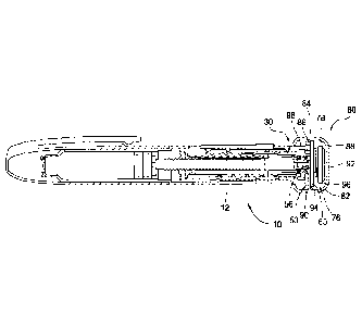
Referring to FIG. 5, there is shown in diagrammatic form a dose delivery
detection
system 80 including a module 82 useful in combination with a medication
delivery device, such
as device 10. Module 82 carries a sensor system, shown generally at 84,
including a rotation
sensor 86 and other associated components such as a processor, memory,
battery, etc Module
82 is optionally provided as a separate component which may be removably
attached to actuator
50.
Dose detection module 82 includes a body 88 attached to dose button 56. Body
88
illustratively includes a cylindrical side wall 90 and a top wall 92, spanning
over and sealing side
wall 90. Body 88 further includes an attachment, such as shown at 94,
attaching module 82 to
dose button 56 such that pressing on the module delivers a set dose. Dose
detection module 82
may be attached to dose button 56 via any suitable fastening means, such as a
snap or press fit,
threaded interface, etc., provided that in one aspect module 82 may be removed
from a first
medication delivery device and thereafter attached to a second medication
delivery device. The
attachment may be at any location on dose button 56, provided that dose button
56 is able to
move any required amount axially relative to dose setting member 30, as
discussed herein.
13
CA 03073279 2020-02-18
WO 2019/036576 PCMJS2018/046860
During dose delivery, dose setting member 30 is free to rotate relative to
dose button 56
and module 82. In the illustrative embodiment, module 82 is rotationally fixed
with dose button
56 and does not rotate during dose delivery. In another embodiment, the distal
pressing of the
module provides a sufficient frictional engagement between module 82 and dose
button 56 as to
functionally cause the module 82 and dose button 56 to remain rotationally
fixed together during
dose delivery.
Top wall 92 is spaced apart from proximal face 60 of dose button 56 and
thereby
provides a compartment 78 containing some or all of electronics assembly 76.
Compartment 78
defines a chamber 96 and may be open at the bottom, or may be enclosed, such
as by a bottom
wall.
In FIG. 6 there is shown an example of a sensed element 98 including
alternating open
portions 100 and closed portions 102. In the embodiment of FIG. 6, the open
and closed portions
are formed by castellation's, in which the open portions are formed by
recesses 104 between
spaced projections 106. Projections 106 extend axially in the proximal
direction. It will be
appreciated, however, that the open portions may instead comprise apertures in
an otherwise
solid wall. The open and closed portions are shown as being formed in a
proximal extension of
dose dial 32, but it will be appreciated that they may also be formed in other
dose setting
members, such as flange 38 or skirt 42
Referring to FIGS. 7 and 8, there are shown two different positions for module
body 88
relative to device housing 12. In FIG. 7, the module is in a first operating
mode in which the
module may be used to set a dose. In certain embodiments, the module and dose
button are
rotationally fixed to the dose setting member in this mode, and module body 88
may be rotated
to set a dose. In this position, projections 106 are axially displaced from
the light source 108 and
the light sensor 110. In addition, wake-up switch 112 is displaced from
contact 114 defined by
the axial proximal end of flange 38. Triggering of wake-up switch 112 is
configured to allow
power transmission from the power source (or battery) for powering up the
electronic
components for dose sensing in order to minimize inadvertent power loss or
usage when a dose
dispensing event is not occurring. As shown, wake-up switch 112 may be located
along the
bottom side or distally facing end 115' of an intermediate body wall 115 of
module 82 that at
least partially transverses an intermediate portion of chamber 96 cavity
defined by body 88 of
module 82. As shown, contact 114 may be located radially inward from housing
of dose dial 32
14
CA 03073279 2020-02-18
WO 2019/036576 PCT/US2018/046860
and in a more distal location relative to an axial proximal end 32' of the
wall of dose dial 32.
Wake-up switch 112 is shown disposed radially between external part of spring
68 and the
interior luminal surface of dose dial 32. Due to the tight area in which the
components are
packaged, it may be beneficial to position wake-up switch 112
circumferentially offset from light
source 108 and sensor 110, such as for example, about 180 degrees from one
another.
Upon pressing top wall 92 of module 82, dose button 56 advances distally
relative to
housing 12, compressing spring 68. Wake-up switch 112 is triggered by being
pressed against
contact 114, and the electronics assembly is activated. In order to prevent
over depression of the
button that could lead to component damage, the axial extent of travel of dose
button/module
combination may be limited. For example, axial proximal end 32' of the wall of
dose dial 32
may define a physical stop that in is in a contacting relationship with
distally facing end 115' of
intermediate body wall 115 of module 82. Such physical stop may also aid in
alignment of said
sensing components for more accurate and consistent readings. At the same
time, rotation sensor
86 is advanced such that projections 106 are received between light source 108
and light sensor
110 (FIG. 8). Continued pressing of the module distally results in back
driving dose dial 32 in a
spiral direction relative to housing 12. FIG. 8 shows the medication delivery
device with module
82, and therefore dose button 56, still depressed but with dose dial 32 having
been driven back to
the zero dose position relative to housing 12.
In the embodiment of FIGS. 5-8, light source 108 and light sensor 110 are
shown
attached to a printed circuit board ("PCB") 116 attached to actuator 50. In
this configuration,
light source 108 is positioned to emit sensing light in a radially-outward
sensing direction. Light
sensor 110 is positioned in alignment with light source 108 to directly
receive the sensing light.
As sensed element 98 rotates, recesses 104 and projections 106 will
successively be positioned in
line with the sensing light being emitted in the sensing direction.
In an alternate embodiment, light sensor 110 is positioned to receive
reflected light rather
than direct light. Referring to FIG. 9, there is shown diagrammatically a dose
detection system
similarly using alternating open and closed portions of the dose setting
member. This
embodiment is comparable to the embodiment of FIGS. 5-8, except for the
positioning of the
light source and light sensor. In FIG. 9, light source 108 and light sensor
110 are positioned
interior of a cylindrical wall 118 including an opening 120. Side wall 90 of
module 82 includes
a reflective surface 122 aligned with opening 120. Light source 108 is
directed outwardly at a
CA 03073279 2020-02-18
WO 2019/036576 PCMJS2018/046860
slight angle from radially to emit sensing light through opening 120 in wall
118. Light emitted
in this direction and passing through open portions 100 in sensed element 98
is reflected back
through opening 120 and is received by light sensor 110.
In either approach, light receptor 110 operates to detect when the sensing
light is and is
not received by light sensor 110 and rotation sensor 86 is thereby able to
detect rotation of dose
setting member 30 relative to actuator 50 during dose delivery.
Referring to FIG. 10, medication delivery device 10 includes a module 200
having a
housing assembly 201 comprising a coupling component 202 and a dosing
component 203.
Coupling component 202 includes a first housing portion 204. Dosing component
203 includes a
second housing portion 206 coupled to first housing portion 204. As described
herein, first and
second housing portions 204, 206 are rotatable relative to each other about a
longitudinal axis
and are axially moveable relative to each other along the axis. First housing
portion 204 includes
a coupling wall 208, illustratively in the form of a cylinder, and a coupling
member 210 fixed to
a distal end of coupling wall 208. Coupling wall 208 and coupling member 210
may be fixed
together via any suitable fastening means, such as a weld, snap fit, threaded
interface, etc., or
alternatively may be integrally formed as a single component. In an
illustrative embodiment,
coupling member 210 includes an annular ridge 212 that extends axially from
the proximal end
forming an annular shoulder 214 between ridge 212 and an outer surface 216 of
coupling
member 210. The distal end of coupling wall 208 includes projection 217 which
snap fits onto
coupling member 210 to rotationally and axially fix coupling member 210 to
coupling wall 208.
When coupled together, the distal end of coupling wall 208 abuts annular
shoulder 214 of
coupling member 210.
Coupling member 210 includes an annular ring portion 218 sized to receive
skirt 42 and
to engage the outer surface of skirt 42 for attaching first housing portion
204 to delivery device
10. As illustrated, outer surface 216 of coupling member 210 tapers radially
inwardly from
shoulder 214 to ring portion 220 such that a proximal end diameter of coupling
member 210 is
larger than a distal end diameter of coupling member 210. An inner surface 222
of ring portion
220 includes a plurality of contour features 224, illustratively variably
sized projections and
grooves, that are sized to engage corresponding surface contours 48 (e.g.,
grooves) of skirt 42 for
coupling thereto. In the illustrated embodiment, surface contours 48 of
coupling member 210
couple to annular ridge 49 of skirt 42 via a snap fit or an interference fit,
although any other
16
CA 03073279 2020-02-18
WO 2019/036576 PCMJS2018/046860
suitable fastening mechanism may alternatively be used to couple first housing
portion 204 to
skirt 42.
In the illustrative embodiment, contour features 224 and surface contours 48
are sized,
shaped, and spaced to provide mechanical keying of housing assembly 201 to
delivery device 10.
In particular, in the illustrative embodiment, housing assembly 201 is
mechanically keyed via
contour features 224 to be compatible with a specific type or types of
delivery devices having
compatible surface contours 48, such as based on medication type,
concentration, strength,
volume, and/or formulation, as well as cartridge size or other aspects of the
corresponding
delivery device. In some embodiments, electronics assembly 76 of module 200 is
pre-
programmed to operate based on the compatible delivery device(s) and/or
medication. Such
mechanical keying serves to reduce the likelihood that detection module 200 is
used with an
incorrect delivery device and/or medication.
With the mechanical key feature, module 200 must be in proper rotational
alignment with
skirt 42 of device 10 to slide and snap coupling member 210 onto skirt 42.
Coupling member
210 illustratively may be provided with a projection or other visual reference
on its outer surface
216 that serves as a guide for rotationally aligning module 200 to skirt 42.
Other keying
features, such as color coding, may be used to identify a correct module 200
for a corresponding
medication delivery device 10.
Second housing portion 206 includes a drum 226 and a cap portion 228 coupled
to a
proximal end of drum 226. Drum 226 illustratively includes inner wall 230 and
a disc-shaped
base wall 232 at a distal end of inner wall 230. Cap portion 228 includes an
end wall 234
positioned orthogonally to inner wall 230. End wall 234 illustratively
includes a distal wall
portion 236 and a proximal wall portion 238 coupled to distal wall portion 236
at a centrally
located mounting interface 240 via a snap fit, interference fit, ultrasonic
weld, or other suitable
coupling mechanism. Cap portion 228 further includes an outer wall 242
radially spaced apart
from and substantially parallel to inner wall 230. In the illustrated
embodiment, coupling wall
208 of first housing portion 204 is positioned in the gap formed radially
between outer wall 242
and inner wall 230 of second housing portion 206. End wall 234 of cap portion
228 includes a
mounting collar 244 axially extending from and centrally located on distal
wall portion 236.
Upper wall portion 246 of inner wall 230 is fixed to mounting collar 244 via
any suitable
coupling mechanism, such as ultrasonic weld or interference fit for example.
17
CA 03073279 2020-02-18
WO 2019/036576 PCMJS2018/046860
When module 200 is attached to delivery device 10, a distal surface of base
wall 232
abuts the proximal end surface of dose button 56. Illustratively, the distal
surface of base wall
232 includes a thin, disc-shaped friction pad 248 having a central opening.
Pad 248 provides
frictional resistance (e.g., via surface roughness and/or adhesive) between
base wall 232 and
dose button 56 such that second housing portion 206 remains rotationally
coupled to dose button
56 during a dosing operation of module 200 with device 10. Base wall 232 of
drum 226 in some
embodiments may include a centrally located, axially extending projection (not
shown)
configured for receipt within a recessed portion of dose button 56, such as
for coupling and/or
alignment of dose button 56 and base wall 232.
In the illustrated embodiment, when dose detection module 200 is attached to
delivery
device 10, first and second housing portions 204, 206 and skirt 42 are coaxial
and are thus
operative to rotate together about a same longitudinal axis during a dose
setting operation of
delivery device 10. In addition, first and second housing portions 204, 206
are operative to move
axially together with skirt 42 along the longitudinal axis during the dose
setting operation and
axially relative to each other along the longitudinal axis in response to an
axial force on second
housing portion 206 to start the dose delivery operation. While coupling wall
208 and inner wall
230 of respective first and second housing portions 204, 206 illustratively
extend 360 degrees
about the longitudinal axis of module 200, walls 208, 230 alternatively may
extend a portion of
the full circumference about the axis. In other words, circumferential walls
208, 230 may
include one or more breaks in the respective wall somewhere along the
perimeter rather than
being continuous walls as illustrated.
Dose detection module 200 is configured for operation in at least a first
operating mode
and a second operating mode. In the illustrated embodiment, the first
operating mode
corresponds to the dose setting operation of delivery device 10, and the
second operating mode
corresponds to the dose dispensing operation of delivery device 10. In the
first operating mode,
shown in FIG. 10, first and second housing portions 204, 206 are at a home
position axially
wherein second housing portion 206 is not axially compressed relative to first
housing portion
204. In this first operating mode, first and second housing portions 204, 206
are rotationally
locked together by a locking mechanism, illustratively a tooth and slot
coupling.
The proximal end of coupling wall 208 of first housing portion 204 includes a
radially
extending annular lip 250 having a plurality of circumferentially spaced slots
252 formed therein.
18
CA 03073279 2020-02-18
WO 2019/036576 PCMJS2018/046860
Slots 252 are each sized to receive a tooth or tongue 254 formed on the outer
surface of upper
wall portion 246 of inner wall 230. Illustratively, four teeth are spaced 90
degrees apart around
upper wall portion 246, and twenty slots 252 are equally spaced around lip
250, although any
suitable number of teeth and slots may be provided. In the illustrative
embodiment, the number
of slots 252 is the same as the number of rotational increments or clicks to
which dose setting
member 30 of device 10 may be set in one complete rotation of dose dial member
32 relative to
housing 12. The multiple slots allow first housing portion 204 and second
housing portion 206
to lock together in the first operating mode in multiple relative rotational
positions, with more
slots providing more possible relative positions. In an alternative
embodiment, slots 252 may be
formed on inner wall 230 and teeth formed on coupling wall 208. Other suitable
rotational
locking mechanisms may be provided.
In general, dosing component 202 in the first operating mode during dose
setting is
axially and rotationally fixed to coupling component 202. In this first mode,
dosing component
203 may be grasped by the user and rotated relative to device body 11. Due to
the connections
between dosing component 203 and coupling component 202, and between coupling
component
202 and dose setting member 30, the rotation of dosing component 203 results
in rotation of dose
setting member 30 and a dose is set. During dose setting, actuator 50,
including dose button 56,
is connected by way of clutch 44 to dose setting member 30 and spirals with
dose setting
member 30 relative to device body 11.
In one embodiment dosing component 203 includes inner wall 230 and outer wall
242,
and coupling component 202 includes coupling wall 208 received between the
inner and outer
walls. Dose setting member 30 includes an exposed circumferential surface 256,
optionally
including surface contours 48, for use in rotating dose setting member 30
relative to device body
11. Coupling wall 208 extends distally beyond inner wall 230 and includes a
coupling portion
258 attached to exposed circumferential surface 256 of dose setting member 30
in order to attach
coupling component 202 to dose setting member 30. In another aspect, as shown
at 260, outer
wall 242 extends distally to radially overlap some or all of the exposed
circumferential surface
256 of the dose setting member and/or the coupling member 210.
Dosing component 203 is rotationally locked with coupling component 202 during
dose
setting. As previously indicated, this may be accomplished by way of a variety
of locking
mechanisms. Illustratively, coupling wall 208 is received in the gap between
inner wall 230 and
19
CA 03073279 2020-02-18
WO 2019/036576 PCMJS2018/046860
outer wall 242. As described, the locking mechanism may comprise mechanical
features, such
as teeth received within slots, or complementary shaped, mutually-facing teeth
extending axially
from the coupling and dosing components. The teeth in either event may, for
example, be
formed on coupling wall 208 of coupling component 202 and on one of the inner
and outer walls
230, 242 of dosing component 203. In a further aspect, to reduce the risk of
damage to the
medication delivery device, the locking mechanism is configured to cause
disengagement of the
dosing component from the coupling component in the event that a rotational
force is applied
from the dosing component to the coupling component in excess of a
predetermined amount.
Illustratively, the locking mechanism is configured also to allow for
disengagement upon
axial movement of dosing component 203 toward coupling component 202. Once
disengaged,
coupling component 202 is free to rotate relative to dosing component 203.
Axial movement of
actuator 50 in the direction of dose setting member 30 results in clutch 52
disconnecting the
rotational engagement of actuator 50 with dose setting member 30. In one
aspect, pressing
housing assembly 201 moves dosing component 203 closer to coupling component
202 and
coupling component 202 is thereby rotationally disengaged from dosing
component 203. This
occurs before actuator 50 moves a sufficient distance to initiate dose
delivery. In another aspect,
a wake-up switch, such as described above, is provided to cause relevant
components of
electronics assembly 76 to activate in time to detect the dose delivery. In
another aspect,
pressing housing assembly 201 disengages dosing component 203 from coupling
component 202
and engages the wake-up switch, and subsequent distal movement presses dose
button 56
sufficiently to cause dose delivery. Although not shown, such wake-up switch
may be
positioned within cavity defined by wall portion 62 of dose button 56 and
configured to contact
the dose dial 32 or flange 38 when in the second mode. In other embodiments,
the wake-up
switch may be other configurations, such as electrical contacts or
accelerometer and may be
positioned within the module body.
Although not required, the disengagement of dosing component 203 from coupling
component 202 may occur such that there is no contact between those two
components once
disengaged. For example, the upper end 262 of coupling wall 208 may be spaced
apart from
mounting collar 244 and the interior 264 of distal wall portion 236. Providing
such a space
avoids contact between coupling wall 208 and outer wall 242, which could
otherwise provide
CA 03073279 2020-02-18
WO 2019/036576 PCT/US2018/046860
frictional resistance to rotation of coupling component 202 relative to dosing
component 203
during dose delivery.
In the second operating mode of module 200, the locking mechanism is
disengaged, and
first and second housing portions 204, 206 are rotatable relative to each
other. An axial
movement or compression of second housing portion 206 relative to first
housing portion 204 is
operative to transition module 200 from the first operating mode to the second
operating mode
by disengaging the locking mechanism to allow relative rotation of first and
second housing
portions 204, 206 about the longitudinal axis of module 200. In particular,
the axial movement
of second housing portion 206 towards first housing portion 204 causes teeth
254 to axially slide
out of corresponding slots 252 to rotationally uncouple first and second
housing portions 204,
206.
In general, in the second operating mode during dose delivery, coupling
component 202
is rotatable relative to dosing component 203. In this second mode, dosing
component 203 is
axially and rotationally fixed to actuator 50. Dosing component 203 is axially
fixed in that the
dosing component bears against actuator 50 as housing assembly 201 is pressed
distally to
deliver a dose. Further, dosing component 203 is rotationally fixed to
actuator 50 either by a
frictional engagement or by other locking means as previously described.
During dose delivery,
actuator 50, including dose button 56, is pressed by the user and translates
axially, while being
held from rotating relative to device body 11. Since clutch 52 has released
the rotational
connection between actuator 50 and dose setting member 30, the dose setting
member spirals
back into device body 11.
In the first operating mode with module 200 coupled to delivery device 10, a
rotational or
screw force on module 200, such as applied to outer wall 242 or any other user
accessible
portion, causes corresponding rotation and axial motion of dose setting member
30 to operate
medication delivery device 10 in the dose setting mode described herein. In
the second operating
mode with module 200 coupled to delivery device 10, the axial force which
compresses module
200 is transferred to dose button 56 and thereby rotationally disengages
actuator 50 from dose
setting member 30, causing dose setting member 30 to screw back into housing
12 to operate
device 10 in the dose delivery mode. During the dose delivery operation of
device 10, first
housing portion 204 screws (moves axially and rotationally) with dose setting
member 30 while
second housing portion 206 remains rotationally fixed while moving only
axially with dose
21
setting member 30. In an exemplary mode of use for attachment of module 200 to
device 10,
the user aligns the visual alignment feature(s) of module 200 and device 10,
and module 200 is
snap fitted to dose setting member 30 of device 10. The locking mechanism
(e.g., teeth 254 and
slots 256) ensures proper alignment of the rotational sensor.
In an exemplary mode of use for dialing a dose, dosing component 203 of module
200 is
rotated relative to housing 12 of device 10, and such rotation is translated
to dose setting member
30 to screw dose dial member 32 up to the desired dose amount. In an exemplary
mode of use
for injecting a dose, cap portion 228 of module 200 is axially pushed relative
to housing 12 to
start an injection. The axial force disengages the locking mechanism in module
200 and the
clutch 52 in delivery device 10, and first housing portion 204 is free to
rotate relative to second
housing portion 206 and dose dial member 32 is free to rotate relative to dose
button 56 of device
10.
When injection ends, the user releases cap portion 228, and electronic
assembly 76
captures the injection event until a certain timeout period, stores the dose
information, and starts
activity in order to automatically update the app running in the remote
smartphone. In case of a
transmission failure, manual sync of module 200 with the smartphone is
possible later to transmit
the dose information. Following transmission, module 20 transitions again to
deep sleep state
(low power mode). In an exemplary mode of use for detaching module 200 from
device 10,
module 200 is detached by pulling module 200 with the required force away from
device 10.
Further details of the design and operation of an exemplary medication
delivery device
may be found in U.S. Patent No. 7,291,132, entitled Medication Dispensing
Apparatus with
Triple Screw Threads for Mechanical Advantage,.
In reference to FIGS. 10-12, an alternate embodiment for the dose detection
system is
shown in combination with a medication delivery device 10. Dose detection
system 300
includes housing assembly 201 including coupling component 202 and dosing
component 203.
Module 200 carries a sensor system, shown generally at 302, including a
rotation sensor 304 and
a sensed element 306. As before, module 200 may be provided as a separate
component which
may be removably attached to the actuator, or the components of module 200 may
be integrated
into the medication delivery device.
22
Date Recue/Date Received 2021-09-03
CA 03073279 2020-02-18
WO 2019/036576 PCMJS2018/046860
Rotation sensor 304 is shown attached to inner wall 230 and comprises two
components,
a light source 308 and a light sensor 310. Both light source 308 and light
sensor 310 are
operatively connected to electronic assembly 76. For example, light source 308
and light sensor
310 may be attached to a printed circuit board ("PCB") forming a part of
electronics assembly
76. Rotation sensor 304 operates in conjunction with sensed element 306 which
is shown
attached through coupling wall 208 and coupling member 210 to dose setting
member 30, for
example skirt 42. Illustratively, sensed element 306 is attached to or is
integral with coupling
wall 208. Although shown as separate elements, coupling member 210 may be
formed integral
with coupling wall 208.
Sensed element 306 in general has an annular shape 311 and is attached to the
interior of
coupling wall 208. Sensed element 306 includes alternating open portions 312
and closed
portions 314. In the embodiment of FIG. 12, the open and closed portions are
formed by
castellation's, in which the open portions are formed by recesses 316 between
spaced projections
318. Projections 318 extend radially-inward. It will be appreciated that the
open portions 312
may instead comprise apertures 320 in an otherwise solid sensed element 306.
Alternatively,
sensed element 306 may be formed integral with coupling wall 208. For example,
sensed
element 306 may be formed as spaced projections attached to or integral with
coupling wall 208
and extending radially inward. The open and closed portions are shown as being
attached
through coupling wall 208 and coupling member 210 to skirt 42. However,
coupling wall 208
may also be attached to any other component of dose setting member 30,
including for example
dose dial 32 or flange 38.
Referring to FIGS. 11-12, further details of dose detection system 300 are
shown. Light
source 308 and light sensor 310 are positioned in FIG. 11 such that light is
emitted by light
source 308 in an axial, distal direction. As shown, the light source 308 and
light sensor 310
radially overlap with projection 318. In this design, the spacing of
projections 318 may be such
as to allow assembly of the module, for example by passage of light source 308
and/or light
sensor 310 between projections 318. This may be further facilitated by a keyed
connection
providing alignment of first housing portion 204 with second housing portion
206. The
embodiment of FIG. 11 may alternatively be configured such that radially
overlapping does not
exist in the assembled module.
23
CA 03073279 2020-02-18
WO 2019/036576 PCT/US2018/046860
Rotation of sensed element 306 relative to rotation sensor 304 occurs during
dose
delivery. The open and closed portions of sensed element 306 are positioned to
intermittently
prevent light from light source 308 being received by light sensor 310. These
intermittent
conditions are detected and used to determine rotation of dose setting member
30 relative to
actuator 50 during dose delivery, and the amount of dose delivered is derived
therefrom.
Dosing component 203 is shown in FIG. 10 in the at-rest position with a dose
not having
been set, as shown by the fact that dose dial 32 and skirt 42 are adjacent
device housing 12. In
setting a dose, the entire housing assembly 201 will translate and rotate away
from device
housing 12. In order to deliver the dose, dosing component 203 is pressed in
the direction of
coupling component 202 and is axially displaced closer to coupling component
202. To
accommodate this relative axial movement, light source 308 and light sensor
310 are axially
spaced sufficiently to allow the axial movement of sensed element 306.
In the method of using dose detection system 300, the dose is set by use of
module 200,
and particularly outer wall 242. Dose delivery is initiated by pressing module
200 distally and
causing back driving of dose setting member 30 in a spiral direction relative
to housing 12.
Light source 308 is positioned to emit sensing light in an axial sensing
direction. Light sensor
310 is positioned in alignment with light source 308 to directly receive the
sensing light. As
sensed element 306 rotates, recesses 316 and projections 318 will successively
be positioned in
line with the sensing light being emitted in the sensing direction.
In an alternate embodiment, light sensor 310 is positioned to receive
reflected light rather
than direct light. Referring to FIG. 13, there is shown diagrammatically a
dose detection system
similarly using alternating open and closed portions of the dose setting
member 30. This
embodiment is comparable to the embodiment of FIG. 12, except for the
positioning of light
source 308 and light sensor 310. Light source 308 emits light at a slight
angle to axial. As a
projection 318 passes in front of the light, the sensing light is reflected
back off of the projection
and impinges on the light sensor 310.
There have thus been described illustrative embodiments of a medication
delivery device
including a module providing components useful to detect the amount of a
delivered dose. The
medication delivery device includes a device body and a dose setting member
attached to the
device body and rotatable relative to the device body about an axis of
rotation during dose
delivery. The device also includes a sensed element attached to and
rotationally fixed with the
24
CA 03073279 2020-02-18
WO 2019/036576 PCMJS2018/046860
dose setting member, the sensed element including alternating first and second
surface features
radially-spaced about the axis of rotation of the dose setting member. An
actuator is attached to
the device body and is non-rotatable relative to the device body during dose
delivery, and the
sensed element rotates relative to the actuator during dose delivery in
relation to the amount of
dose delivered.
A module is axially and rotationally fixed with the actuator during dose
delivery. The
module comprises a rotation sensor including a light source emitting sensing
light in a sensing
direction during dose delivery. The rotation sensor further includes a light
sensor positioned to
receive the sensing light emitted in the sensing direction. Rotation of the
sensed element during
dose delivery positions the first and second surface features in the path of
the sensing light. The
first surface features result in the sensing light being detected by the light
sensor, and the second
surface features result in the sensing light not being detected by the light
sensor. The rotation
sensor is responsive to the detection of the sensing light to detect rotation
of the dose setting
member relative to the actuator during dose delivery. The module further
comprises an
electronics assembly responsive to the rotation sensor to determine the amount
of dose delivery
based on the detected rotation of the dose setting member relative to the
actuator during dose
delivery.
Illustratively in one embodiment, the module has a first operating mode and a
second
operating mode relative to said actuator. The module in the first operating
mode during dose
setting is directly attached to the actuator and is axially and rotationally
fixed to the dose setting
member. The module in the second operating mode is axially and rotationally
fixed to the
actuator and is rotatable relative to the dose setting member during dose
delivery. The module
optionally moves axially distally from the first operating mode to the second
operating mode.
In an alternate embodiment, the dose detection system includes a coupling
component
which is attached directly to the dose setting member. The dose detection
system further
includes a dosing component which is axially and rotationally fixed to the
actuator in a second
operating mode during dose delivery. The coupling component and the dose
setting member are
rotatable relative to the actuator and the dosing component during dose
delivery. In one aspect,
the dosing component moves axially distally from the first operating mode to
the second
operating mode. In another aspect, the coupling component is axially fixed to
the dosing
component during dose setting, and is rotatable relative to the dosing
component during dose
CA 03073279 2020-02-18
WO 2019/036576 PCT/US2018/046860
delivery. In an exemplary form, the dose setting member includes an exposed
circumferential
surface for use in rotating the dose setting member relative to the device
body for setting a dose,
and the coupling component includes a coupling portion attached to the exposed
circumferential
surface of the dose setting member.
In one aspect, the dose detection system is originally incorporated into a
medication
delivery device as an integrated system. In another aspect, there is disclosed
a modular form of
the dose detection system. The use of a removably attached module is
particularly adapted to
use with a medication delivery device in which the actuator and/or the dose
setting member
include portions external to the device housing. These external portions allow
for direct
attachment of the module to the actuator, such as the dose button or skirt,
and also attachment of
the sensed element to the dose setting member, such as a skirt, flange, or
dose dial member.
Alternatively, the sensed element is integral with the medication delivery
device and the module
is removably attached. This has the advantage that the more complex and
expensive electronics,
including the rotation sensor and controller, may be reused with different
medication deliver
devices. By comparison, the sensed element may use relatively simple features,
for example
radially-spaced projections, which do not add significantly to the cost of the
medication delivery
device. Any of the devices described herein may comprise any one or more of
medications
described herein, such as, for example, within the cartridge of the device.
26