Note: Descriptions are shown in the official language in which they were submitted.
CA 03073633 2020-02-21
WO 2019/043248 PCT/EP2018/073730
1
A wind turbine blade and a method of manufacturing the wind
turbine blade
Technical field
The present invention relates to a wind turbine blade component for a wind
turbine blade,
the wind turbine blade component comprises a plurality of layers of fibre
material,
wherein said plurality of layers comprises a first group of layers and at
least a second
group of layers.
The present invention also relates to a wind turbine blade comprising such a
wind turbine
blade component, and a method of manufacturing the wind turbine blade
component.
Background
It is known to integrate the spar caps or main laminates into the blade shell
of the wind
turbine blade during the manufacturing process. Alternatively, the main
laminates may
be attached to the blade shell in a post-moulding process. The main laminates
are inter-
connected via one or more shear webs, l-beams or box beams. It is further
known that
the main laminates comprise a laminated stack of one or more fibre materials
infused
with a suitable resin and finally cured.
US 2011/0243750 Al discloses a spar cap formed by a stack of individual layers
of a
fibre material which are cut into individual lengths and arranged to form a
stack having a
tapered end profile in the lengthwise or longitudinal direction. The
individual layers are
further cut to form a uniform lengthwise profile with a constant width, or to
form a tapered
lengthwise profile where the width tapers from the blade root to the tip end.
US 2012/0082554 Al discloses at least two stack portions each comprising a
plurality of
individual layers having a uniform width in a lengthwise direction. The
individual stack
portions are jointed together in the lengthwise direction to form the spar
cap. In one em-
.. bodiment, the layers in each stack portion are individually offset relative
to each other to
form a zig-zag shaped end profile which extends uniformly in an edgewise
direction. In
an alternative embodiment, one or more fingers project from the opposite
facing ends of
each layer of each stack portion in the lengthwise direction. The opposite
facing fingers
form an overlapping finger joint extending in the edgewise direction. This
solution
CA 03073633 2020-02-21
WO 2019/043248 PCT/EP2018/073730
2
provides a complex joint which requires an accurate alignment and lay-up of
each stack
portion.
US 2009/0169392 Al discloses a spar cap formed by a trapezoid stack of
individual
layers where the width of each layer tapers from one side to the opposite
side. In an
alternative embodiment, the stack comprises a plurality of layers of the same
width di-
vided into two groups which are offset in opposite edgewise directions to a
relative wide
rectangular shaped cross-sectional profile. Each group partly overlap the
inclined end
surface of an adjacent core element so that the overlapping edges of that
group form an
edge profile extending substantially perpendicular to the inclined end
surface. The op-
posite edges of that group form an edge profile extending parallel to the
thickness direc-
tion. Wrinkles are formed in the overlapping portions of the layers due to the
angular
transition between the outer skin of the blade shell and the tapered end of
the core ele-
ment. Furthermore, relative large recesses are formed in the inner blade
surface as the
spar cap only extends partly along the tapered end of the core element.
US 5755558 A discloses a stacked spar structure comprising one group of a high
mod-
ulus UD fibre material and another group of a low modulus US fibre material,
wherein
the layers in each group are offset in the same edgewise direction. Each group
of layers
has a layer width that differs from the layer width of the adjacent groups.
US 2012/0009070 Al discloses a wind turbine blade shell comprising a plurality
of pre-
cured shell elements arranged in at least two separate layers. The shell
elements in each
layer is angled in different edgewise directions.
Object of the invention
An object of the invention is to provide a wind turbine component, a wind
turbine blade
and a method that solves the abovementioned problems.
Another object of the invention is to provide a wind turbine component, a wind
turbine
blade and a method that saves fibre materials and reduces manufacturing costs.
Yet another object of the invention is to provide a wind turbine component, a
wind turbine
blade and a method that allows for a fast and simple lay-up of the fibre
material.
CA 03073633 2020-02-21
WO 2019/043248 PCT/EP2018/073730
3
Detailed description of the invention
An object of the invention is achieved by a wind turbine blade component for a
wind
turbine blade, the wind turbine blade component extending from a first end to
a second
end in a lengthwise direction and further from a first edge to a second edge
in an edge-
wise direction, the wind turbine blade component comprises a plurality of
layers of fibre
material arranged in a stack extending in a thickness direction, wherein the
stack defines
a first side and a second side where the first and second edges are arranged
between
the first and second sides, said plurality of layers comprises a first group
of layers and at
least a second group of layers, the layers of said first group has a first
local width and
the layers of said second group has a second local width, wherein the layers
of at least
one of said first and second groups are continuously offset in at least one
edgewise
direction from the first side to the second side, where the layers of said
first group are
offset in a first edgewise direction to form a first edge profile and the
layers of said second
group are offset in a second edgewise direction to form a second edge profile,
charac-
tensed in that the first edgewise direction is opposite of the second edgewise
direction.
This provides a wind turbine blade component with an alternative stacked
configuration
that allows for a simplified lay-up process. The stack may advantageously be
formed
using a reduced number of rolls with different widths of a fibre material
compared with
conventional methods. This also reduces the amount of cutting required as all
layers in
each group have the same width. Any adjustments in width may thus be performed
in a
common step for all layers of a selected group. The layers may also be pre-cut
into the
desired width and provided on rolls. This further reduces the total number of
item num-
bers required for manufacturing the wind turbine blade components. This allows
for an
optimised usage of structural materials to minimise wind turbine blade mass
and cost.
The wind turbine blade component is formed as a main laminate which may be
integrated
into the aerodynamic part of the blade shell during manufacturing, or
manufactured sep-
arately and later attached to the aerodynamic part of the blade shell. The
wind turbine
blade component has a length measured between a first end and a second end in
a
lengthwise direction, a width measured between a first edge and a second edge
in an
edgewise direction, and a thickness measured between a first side and a second
side in
a thickness direction. The shape and dimensions of the wind turbine blade
component
may be adapted to the aerodynamic profile and/or the geometric dimensions of
the wind
turbine blade.
CA 03073633 2020-02-21
WO 2019/043248 PCT/EP2018/073730
4
The wind turbine blade component is formed by a plurality of individual
layers, e.g. plies,
of a fibre material arranged in a stacked configuration. The individual layers
are divided
into two or more groups each comprising a plurality of layers. For example,
each group
comprises two, three, four, five, six, seven or more layers. The individual
layers in each
group have a local length, a local width and a local thickness. The number of
layers in
each group may be uniform, or vary relative to each other. The total number of
groups
may be selected dependent on the desired structural stiffness and profile of
the wind
turbine component.
The individual layers in at least one group are continuously offset in one
edgewise direc-
tion from one side to the opposite side. The width offset of each layer may be
determined
relative to a reference layer, i.e. a selected layer within that group or
within another group.
For example, the relative width offset may increase uniformly from the first
side to the
second side, or vice versa. For example, the relative width offset may vary
between the
first and second sides. The individual first edges of the layers together form
a first edge
profile and the individual second edges of the layers together form a second
edge profile.
The first and second edge profiles may face in the same overall edgewise
direction or in
opposite edgewise directions. This reduces the formation of wrinkles in the
fibre material
and allows the respective edge profiles to match the corresponding end
profiles of the
adjacent core elements so that the wind turbine component and the core
elements form
a substantial continuous or smooth transition at the inner blade surface. This
also pro-
vides an improved interface between the wind turbine blade component and the
aerody-
namic part of the wind turbine blade.
Offsetting the individual layers form a tapered joint defining a gradual
transition between
the wind turbine blade component and the adjoining core element. This provides
an op-
timal transition in stiffness and lowers stress concentrations in this tapered
joint.
Further, the layers of said first group are offset in a first edgewise
direction to form a first
edge profile and the layers of said second group are offset in a second
edgewise direc-
tion to form a second edge profile.
CA 03073633 2020-02-21
WO 2019/043248 PCT/EP2018/073730
Preferably, the stack comprises a first group of layers and at least a second
group of
layers. The number of layers in the first and second groups may vary or be the
same.
The individual layers in the first group may be offset in a first edgewise
direction so that
the individual first or second edges together form a first edge profile. The
individual layers
5 in the second group may be offset in a second edgewise direction relative to
the first
edgewise direction so that the individual first or second edges together to
form a second
edge profile. The stack may optionally comprise further groups where the
individual lay-
ers in these further groups may be offset in a further edgewise direction that
differs from
the first and second edgewise directions.
The relative width offset of the first group and/or of the second group may be
selected
dependent on the aerodynamic profile and geometrical dimensions of the wind
turbine
blade. For example, the relative width offset of the first group may be equal
to the relative
width offset of the second group. The first and second edge profiles may thus
be angled
equally or symmetrical relative to the thickness direction. For example, the
relative width
offset of the first group may differ from the relative width offset of the
second group. The
first and second edge profiles may thus be angled differently relative to the
thickness
direction. This allows the respective edge profiles to form a tapered joint
with a relative
short or long transition measured in the edgewise direction.
Further, the first edgewise direction is opposite of the second edgewise
direction. Alter-
natively, the first edgewise direction is equal to the second edgewise
direction.
The individual layers of the first group and of the second group may be offset
in opposite
edgewise directions so that the wind turbine blade component may form a zig-
zag
shaped edge profile. Here, the zig-zag profile may be defined by the combined
first edge
profiles or second edge profiles of the above groups. This allows the
respective edge
profiles to form a relative short tapered joint with two tapered edge
portions, e.g. a sub-
stantially V-shaped joint.
CA 03073633 2020-02-21
WO 2019/043248 PCT/EP2018/073730
6
Alternatively, the individual layers of the first group and of the second
group may also be
offset in the same edgewise direction so that the individual first or second
edge profiles
may extend parallel relative to each other or in different angular positions.
The individual
layers of the first and second groups may both be offset relative to the same
starting
point, i.e. the reference layers may be aligned. This allows the respective
edge profiles
to form an alternative tapered joint with two tapered edge portions, e.g. a
stepped or
sawtooth shaped joint.
The individual layers of the first and second groups may also be offset
relative to different
starting points, i.e. the reference layers may be offset. The first side may
thus be formed
by the combined first outermost layers of the first and second groups and the
second
side may thus be formed by the combined second outermost layers of the first
and sec-
ond groups. This allows the respective outermost layers to form a side with a
combined
total width greater than the local width of each outermost layer.
Alternatively, the individual layers of the first group and of the second
group may also be
continuously offset in the same edgewise direction so that the width offset is
continuously
increased in the thickness direction. The individual first or second edge
profiles may thus
a continuous edge surface with different angular portions. This allows the
respective
edge profiles to form a relative long tapered joint with a single tapered edge
portion.
According to one embodiment, an outermost layer of said first group is aligned
with an
outermost layer of said second group in the thickness direction.
The first group may comprise a first outermost layer facing the first side and
a second
outermost layer facing the second side. This first or second outermost layer
may be used
as reference for offsetting the other layers of the first group. Similarly,
the second group
may comprise a first outermost layer facing the first side and a second
outermost layer
facing the second side. This first or second outermost layer may be used as
reference
for offsetting the other layers of the second group.
CA 03073633 2020-02-21
WO 2019/043248 PCT/EP2018/073730
7
The reference layer of the first group may be aligned with the reference layer
of the
second group in the thickness direction. Alternatively, the two reference
layers may be
offset relative to each other in the edgewise direction. For example, the
first or second
outermost layers of the first and second groups may be used as reference
layers. This
allows an outermost layer of the first group to partly or fully overlap an
adjacent outermost
layer of the second group in the edgewise direction, or vice versa.
Further, a local width offset between the reference layer and a selected layer
in the first
group may be equal to or differ from a local width offset between
corresponding layers
in the second group. For example, the local width offsets between the first
and second
outermost layers of the first group and of second group may be the same. The
same
may apply to any other corresponding layers between the first and second
groups.
According to one embodiment, the layers of the second group are offset
relative to an
outermost layer of the first group.
Alternatively, the first or second outermost layer of the first group may be
used as the
reference layer for offsetting the layers of the second group. This reference
layer may
thus be partly overlapped by an adjacent outermost layer of the second group.
Option-
ally, this adjacent outermost layer may further be aligned with the reference
layer used
for offsetting the layers of the first group. Thereby, forming a greater
relative width offset
between these two adjacent outermost layers of the first and second groups.
According to one embodiment, the layers of at least the first or second group
are ar-
ranged in a continuous order in the thickness direction.
The individual layers of the first group may be arranged in a continuous order
along the
thickness of the stack. Further, the individual layers of the second group may
be ar-
ranged in a continuous order along the thickness of the stack. The first and
second
groups may thus be arranged adjacent to each other. This allows the layers of
each
group to be laid up in a continuous process.
According to one embodiment, the layers of the first group and the layers of
the second
group are arranged in an alternating order in the thickness direction.
CA 03073633 2020-02-21
WO 2019/043248 PCT/EP2018/073730
8
The individual layers of the first group and the individual layers of the
second group may
instead be arranged in an alternating order along the thickness of the stack.
This allows
the layers of the first and second groups to be laid up in an alternating
process.
According to one embodiment, said plurality of layers form a tapered stack,
wherein a
total width of said tapered stack tapers from the first side to second side or
a total thick-
ness of said tapered stack tapers from a layer defining one of said first and
second sides
to a layer defining the other of said first and second sides.
The total number of individual layers defining the stack may be arranged to
form a ta-
pered profile extending in the edgewise direction and in the thickness
direction. This
tapered profile may define a total width and a total thickness of the wind
turbine blade
component. For example, but not limited to, the stack may comprise at least
ten layers,
preferably between twenty and eighty layers.
For example, the individual layers of the first and second groups may be
arranged to
form a substantially uniform cross-sectional profile having a substantial
uniform total
width along the thickness of the wind turbine blade component. For example,
this uniform
cross-sectional profile may be shaped as a parallelogram. The total thickness
of the wind
turbine blade component may taper in the edgewise direction from a layer
defining the
first side to a layer defining the second side, or vice versa. Here, the
'parallelogram' is
defined as any geometrical shape having parallel first and second sides and
parallel first
and second edges. This allows for a substantially uniform overlap between
adjacent lay-
ers in the stack.
For example, the individual layers of the first and second groups may be
arranged to
form a trapezoid shaped cross-sectional profile where the total width may
taper along
the thickness of the wind turbine blade component from the first side to the
second side,
or vice versa. Here, the 'trapezoid' is defined as any geometrical shape
having parallel
first and second sides and non-parallel first and second edges.
CA 03073633 2020-02-21
WO 2019/043248 PCT/EP2018/073730
9
This tapered stack may form a sub-part of a larger overall tapered stack of
the wind
turbine blade component. A third group of layers and a fourth group of layers
may be
arranged to form at least another sub-part of this overall tapered stack. Said
another sub-
part may be positioned at the first or second side of the above first and
second groups
of layers. The individual layers of the third and fourth groups may each have
a local width
which differs from the local width of the first and/or second group of layers.
For example,
the layers of the third and/or fourth group may have a width greater or
smaller than the
width of the layers of the first and/or second group. Further, the layers of
the first and
second groups may be arranged in an alternating order and/or the layers of the
third and
.. fourth groups may be arranged in an alternating order. This allows the
local width of the
individual layers in each sub-part to be adapted to the overall total
thickness of this wind
turbine blade component. This also allows for the manufacture of relative
thick wind tur-
bine blade components or wind turbine blade components with a relative long
edgewise
transitional area.
Alternatively, the individual layers of the first and second groups may be
arranged to
form one half of a symmetrical profile of the wind turbine blade component
where the
other half of this symmetrical profile may be formed by a transformed copy of
the first
and second groups. The transformed copy may be formed by rotation, scaling,
reflection
or any combinations thereof. The total width of this wind turbine blade
component may
taper along the thickness of the wind turbine blade component from a
centreline to the
first side and/or to the second side. Thus, a maximum overlap between adjacent
layers
may be located towards the first or second side while a minimum overlap
between adja-
cent layers may be located towards the centreline.
According to one embodiment, said first local width is equal to said second
local width,
or said first local width differs from the second local width.
The individual layers in the first group may each have a first width, a first
length and a
first thickness. Further, the individual layers in the second group may each
have a sec-
ond width, a second length and a second thickness.
CA 03073633 2020-02-21
WO 2019/043248 PCT/EP2018/073730
The layers of both the first and second groups may have the same local width,
i.e. the
first width may be equal to the second width. Alternatively, the layers of the
first group
and the layers of the second group may have different local widths, i.e. the
first width is
greater or smaller than the second width. This allows the local width of the
layers in each
5 group to be adapted to the aerodynamic profile and geometrical profile of
the wind turbine
blade.
According to one embodiment, the layers of said first group further have a
first local
length and the layers of said second group further have a second local length,
wherein
10 either said first local length is equal to said second local length or
said first local length
differs from the second local length.
The individual layers of at least one group may be aligned at the first end or
at the second
end. Alternatively, the individual layers may be continuously offset in one
lengthwise di-
rection relative to a reference layer. The length offset of each layer may be
determined
relative to the above reference layer or another reference layer. For example,
the relative
length offset may increase uniformly or vary from the first side to the second
side, or vice
versa. The individual first ends and the individual second ends of these
layers may to-
gether each form a tapered end profile facing in the same lengthwise
direction. Thereby,
forming another tapered joint between the wind turbine blade component and an
adja-
cent part of the blade shell. This further reduces the risk of wrinkles
forming in the lami-
nated layers during manufacture and further reduces the risk of delamination
in the ta-
pered joints. This also allows the total thickness of the wind turbine blade
component to
taper off, e.g. in steps or gradually, in the lengthwise direction towards the
tip end and/or
the blade root.
The individual layers of first group and the individual layers of the second
group may
each have the same local length, i.e. the first length may be equal to the
second length.
Alternatively, the layers of the first group and the layers of the second
group may have
different local lengths, i.e. the first length may be greater or smaller than
from the second
length. This allows the local length of the layers of each group to be adapted
to the
aerodynamic profile and geometrical profile of the wind turbine blade.
CA 03073633 2020-02-21
WO 2019/043248 PCT/EP2018/073730
11
In a special configuration, the layers of the first group may have a first
length extending
beyond the second length of the layers of the second group. The layers of the
second
group may further have a second width extending beyond the first width of the
first group.
Optionally, layers of a third group may have a third length extending less
than the second
.. length and may further have a third width extending beyond the second
width. This allows
the wind turbine blade component to extend further into the tip end region and
thus have
a longer total length. This further allows the total width and/or total
thickness of the wind
turbine blade component to taper off, e.g. in a stepped manner, as it extends
further into
the tip end region.
In this special configuration, the layers of the first group, the second group
and optionally
the third group may further be aligned relative to a common central line in
the edgewise
direction or offset towards the first or second edge of the wind turbine blade
component.
Alternatively or additionally, the layers of the first group, the second group
and optionally
.. the third group may be aligned centrally in the lengthwise direction or
offset towards the
first or second end of the wind turbine blade component.
In an alternative special configuration, the layers of one or more selected
groups may be
offset both in the edgewise and lengthwise directions. For example, the layers
of one
group may be offset differently in both the edgewise and lengthwise directions
relative to
the layers of another group. For example, the layers of one group may be
offset in both
the edgewise and lengthwise directions while the layers of another group may
be offset
only in the edgewise direction. For example, the layers of all groups may be
offset in both
the edgewise and lengthwise directions.
The local thickness of the layers in each group may be the same.
Alternatively, the local
thickness of the layers of the first group may be smaller than the local
thickness of the
layers of the second group, or vice versa. This further allows the profile of
the wind tur-
bine blade component to be adapted to the aerodynamic profile and geometrical
dimen-
sions of the wind turbine blade.
An object of the invention is further achieved by a method of manufacturing a
wind tur-
bine blade component as described above, comprising the steps of:
- laying up a first group of layers of a fibre material in a mould, wherein
each layer of said
first group has a first local width,
CA 03073633 2020-02-21
WO 2019/043248 PCT/EP2018/073730
12
- further laying up at least a second group of layers of the fibre material,
wherein each
layer of said at least second group has a second local width,
- infusing said fibre material with a resin,
- substantially curing said resin to form a wind turbine blade component,
characterised in that the laying up of at least one of said first and second
groups of layers
comprises continuously offsetting subsequent layers of said at least one of
the first and
second groups of layers in one edgewise direction relative to a reference
layer of said at
least one of the first and second groups of layers.
This provides a simplified lay-up process of the layers forming the wind
turbine blade
component using a reduced number of rolls with fibre material. This also
reduces the
total item numbers used to manufacture the wind turbine blade component
compared to
conventional methods. A minimal amount of cutting is thus required to form
each individ-
ual layer in that group, as any adjustment in width can be performed in a
common step.
The present invention also minimizes the mass and cost of the wind turbine
blade by an
optimised usage of structural materials during manufacturing.
The wind turbine blade component may be laid up in a separate mould and,
optionally,
infused with resin and then cured. The cured wind turbine blade component may
then be
positioned and attached to the rest of the blade shell structure in a later
step. Alterna-
tively, the wind turbine component may be laid up directly in a recess formed
in a blade
shell structure arranged in a blade mould.
The lay-up of the stack can thus be performed by simply offsetting the
individual layers
in the edgewise or chordwise direction in order to form the desired cross-
sectional profile.
This may be done manually by hand or via the automated lay-up equipment. In
conven-
tional methods, the roll with fibre material has to be exchanged for each
layer in order to
provide the tapered cross-sectional profile. The tapered cross-sectional
profile may also
be formed in some conventional methods by individually cutting each layer in
width. The
present invention enhances the infusion properties of the wind turbine blade
component
and provides an improved interface between the aerodynamic part and the wind
turbine
blade component.
According to one embodiment, at least one of said first and second groups of
layers is
laid up in a continuous step.
CA 03073633 2020-02-21
WO 2019/043248 PCT/EP2018/073730
13
Each group of layers may be laid up in a continuous order and thus in
individual contin-
uous steps. Thereby, the first group of the layers may be laid up in a first
step and the
second group of layers may be laid up in a second step. This allows for fast
and simple
lay-up of each individual group of layers. The individual layers of each group
may simply
be cut in length during lay-up, or be supplied as pre-cut items. A first layer
may be initially
laid up and function as a reference layer for offsetting the subsequent
layers. The sub-
sequent layers may be laid up by simply offsetting them in the edgewise
direction relative
to the reference layer.
According to one embodiment, said first and second groups of layers are laid
up in alter-
nating order.
The first and second groups of layers may also be laid up in an alternating
order and
thus in a combined step.
For example, a first layer of the first group may initially be laid up in the
mould and func-
tion as a first reference layer for offsetting the subsequent layers of the
first group. Then,
a first layer of the second group may be laid up on top of the first layer of
the first group
and function as a second reference layer for offsetting the subsequent layers
of the sec-
ond group. Optionally, this second reference layer may be offset in the
edgewise direc-
tion relative to the first reference layer. A second layer of the first group
may afterwards
be laid up on top of the first layer of the second group and offset relative
to the first
reference layer. A second layer of the second group may then be laid up on top
of the
second layer of the first group and offset relative to the second reference
layer. And so
forth. This process may be repeated until all layers of the first and second
groups are
laid up.
For example, a first layer of the first group may initially be laid up in the
mould and func-
tion as a common reference layer for offsetting the subsequent layers of the
first and
second groups. Then, a first layer of the second group may be laid up on top
of the first
layer of the first group and offset in the edgewise direction relative to this
common refer-
ence layer. A second layer of the first group may afterwards be laid up on top
of the first
layer of the second group and offset relative to the common reference layer. A
second
layer of the second group may then be laid up on top of the second layer of
the first group
and offset relative to the common reference layer. And so forth. This process
may be
repeated until all layers of the first and second groups are laid up.
CA 03073633 2020-02-21
WO 2019/043248 PCT/EP2018/073730
14
The subsequent layers of the first group may be continuously offset in the
first edgewise
direction during the lay-up. Similarly, the subsequent layers of the second
group may be
continuously offset in the second edgewise direction during the lay-up. The
first and sec-
ond edgewise directions may substantially face in opposite edgewise
directions. Alter-
natively, each subsequent layer of the first and second groups may offset in
the same
overall edgewise direction, but with different width offsets, during the lay-
up. Alterna-
tively, each subsequent layer of one group may offset in one edgewise
direction while
each subsequent layer of the other group may be aligned in the thickness
direction, i.e.
have a width offset of zero, during the lay-up. This forms a stack having a
trapezoid or
parallelogram shaped cross-sectional profile.
According to one embodiment, the layers of a group having the greatest local
length of
said stack and/or the smallest local width of said stack are laid up in an
initial sub-step.
The individual layers within each group may be laid up in a predetermined
order, as
described above.
The individual groups may be arranged so that the group of layers having the
greatest
local width may be laid up in the mould or recess in an initial sub-step. The
group of
layers having the second-greatest local width may be laid up in a subsequent
sub-step
on top of these layers. This process may be repeated until the group of layers
having the
smallest local width are laid up in the mould or recess in a final sub-step.
The groups
may also be laid up in a reversed order so that the narrowest layers are
initially laid up
while widest layers are finally laid up. The layers may thus form a stack with
a tapered
cross-sectional profile.
Additionally or alternatively, the individual groups may be arranged so that
the group of
layers having the greatest local length may be laid up in the mould or recess
in an initial
sub-step. The group of layers having the second-greatest local length may be
laid up in
a subsequent sub-step on top of these layers. This process may be repeated
until the
group of layers having the smallest local length are laid up in the mould or
recess in a
final sub-step. The groups may also be laid up in an reversed order so that
the shortest
layers are initially laid up while longest layers are finally laid up. The
layers may thus
form a stack with a tapered lengthwise profile.
CA 03073633 2020-02-21
WO 2019/043248 PCT/EP2018/073730
According to one embodiment, at least one layer of said first group or second
group is
laid up in an inclined angle relative to the lengthwise direction of another
layer of the first
group or second group, and/or at least one layer of said first group or second
group is
laid up in a curved direction relative to the lengthwise direction.
5
In another special embodiment, one or more groups of layers may be placed in a
prede-
termined angle relative to the lengthwise direction. Alternatively, the layers
within one
group may be placed in predetermined angles relative to the lengthwise
direction. This
angle may be measured from the first end towards the second end, or vice
versa.
For example, the individual group of layers and/or layers within one group may
be angled
individually in relation to the lengthwise direction so that an angular offset
exists between
adjacent groups. At least one group or layer may extend parallel to the
lengthwise direc-
tion while the other groups or layers may be placed in an uniformly increasing
angle
along the thickness direction. Alternatively, one group or layer may be angled
towards
the first edge while at least one further group or layer may be angled towards
to the
second edge. The angle may alternatively vary along the thickness direction.
In example,
but not limited to, the angular offset may 0.50, 1 , 1.50, 2 or even greater
or even smaller.
This provides an overall profile where the total width varies along the
lengthwise direc-
tion.
In yet another special embodiment, one or more groups of layers may extend in
a cured
direction relative to the lengthwise direction. The curvature may be measured
from the
first end towards the second end, or vice versa.
For example, the individual groups of layers and/or the individual layers
within one group
may be individually curved or have the same curvature in relation to the
lengthwise di-
rection. At least one group or layer may extend parallel to the lengthwise
direction while
the other groups or layers may be curved towards the first or second edge.
Alternatively
or additionally, at least one group or layer may be curved towards the first
edge while at
least one other group or layer may be curved towards the second edge. This
provides
an overall profile suitable for twisted or pre-bend wind turbine blades.
The above curvature or angular placement may be selected dependent on the
chordwise
position of the wind turbine blade component and/or the aerodynamic profile of
the wind
turbine blade.
CA 03073633 2020-02-21
WO 2019/043248 PCT/EP2018/073730
16
An object of the invention is also achieved by a wind turbine blade for a wind
turbine,
extending from a blade root to a tip end in a longitudinal direction and
further from a
leading edge to a trailing edge in a chordwise direction, the wind turbine
blade comprises
a blade shell forming a pressure side and a suction side and a load carrying
structure
arranged between the pressure side and the suction side, wherein said load
carrying
structure comprises at least one main laminate located at the pressure side
and at least
one main laminate located at the suction side, characterised in that at least
one of said
main laminates at the pressure and suction sides is configured as described
above.
This provides a wind turbine blade with at least one main laminate arranged in
the pres-
sure side and in the suction side, respectively. Each main laminate extends in
the longi-
tudinal direction and further in the chordwise direction. The main laminates
are preferably
manufactured, as described earlier, and provide an improved transition between
the
main laminate and the aerodynamic part of the blade shell.
An outer skin comprising a number of outer layers of a fibre material may
extend along
the first side of the main laminate. A number of core elements and the stack
of layers of
the main laminate may then be arranged on this outer skin. The stack extends
in the
thickness direction, e.g. perpendicular to the chord or the camber line. An
inner skin
comprising a number of inner layers of the fibre material may extend along the
second
side of the main laminate. This provides a sandwich structure which may be
infused with
resin and finally cured. This provides an integrated main laminate structure
with improved
infusion properties which, in turn, reduces the risk of wrinkles forming in
the laminated
layers.
Alternatively, the core elements may be spaced apart to form a recess for
receiving the
main laminate. The inner skin may extend along the end surfaces of these
adjacent core
elements and further along the outer skin. The stack of layers of the main
laminate may
afterwards be arranged within this recess and then infused with resin and
finally cured.
This allows the wind turbine blade to be manufactured in a two-step process.
Description of drawings
The invention is explained in detail below with reference to embodiments shown
in the
drawings, in which
Fig. 1 shows a wind turbine,
CA 03073633 2020-02-21
WO 2019/043248 PCT/EP2018/073730
17
Fig. 2 shows an exemplary embodiment of the wind turbine blade,
Fig. 3 shows a first embodiment of the wind turbine blade component
integrated
into the blade shell,
Fig. 4 shows a second embodiment of the wind turbine blade component,
Fig. 5 shows the wind turbine blade component attached to an aerodynamic
part
of the blade shell,
Fig. 6 shows a first embodiment of the stack comprising a first group
of layers
and a second group of layers arranged in a continuous order,
Fig. 7 shows a second embodiment of the first group and the second
group,
Fig. 8 shows a third embodiment of the first group and the second group,
Fig. 9 shows a fourth embodiment of the first group and the second
group,
Fig. 10 shows a fifth embodiment of the first group and the second
group,
Fig. 11 shows a sixth embodiment of the first group and the second
group,
Fig. 12 shows a seventh embodiment of the first group and the second
group,
Fig. 13 shows an eighth embodiment of the stack where the first group of
layers
and the second group of layers are arranged in an alternating order,
Fig. 14 shows a ninth embodiment of the first group and the second
group,
Fig. 15a-b show two alternative first embodiments of a wind turbine blade
component
formed by at least two sub-parts,
Fig. 16a-b show two alternative second embodiments of the wind turbine blade
com-
ponent formed by at least two sub-parts,
Fig. 17 shows a tenth embodiment of the wind turbine blade component,
Fig. 18 shows an eleventh embodiment of the wind turbine blade
component,
Fig. 19 shows a twelve embodiment of the wind turbine blade component,
Fig. 20 shows a thirteenth embodiment of the wind turbine blade component,
Fig. 21 shows a fourteenth embodiment of the wind turbine blade
component, and
Fig. 22 shows a fifteenth embodiment of the wind turbine blade
component.
List of references
1. Wind turbine
2. Wind turbine tower
3. Nacelle
4. Hub
5. Wind turbine blades
6. Pitch bearing
7. Blade root
CA 03073633 2020-02-21
WO 2019/043248
PCT/EP2018/073730
18
8. Tip end
9. Leading edge
10. Trailing edge
11. Blade shell
12. Pressure side
13. Suction side
14. Blade root portion
15. Aerodynamic blade portion
16. Transition portion
17. Length of wind turbine blade
18. Chord length of wind turbine blade
19. Blade thickness
20. Core elements
21. Inner skin
22. Outer skin
23. Main laminate
24. First side
25. Second side
26. First edge
27. Second edge
28. End surfaces of core elements
29. Aerodynamic part of blade shell
30. First group of layers
31. Second group of layers
32. First outermost layer
33. Second outermost layer
34. Width offset
35. First edge profile
36. Second edge profile
37. Main laminate
38. Sub-parts of the main laminate
39. Halves of the main laminate
40. Central line
41. Third group of layers
42. First end
43. Second end
CA 03073633 2020-02-21
WO 2019/043248 PCT/EP2018/073730
19
44. Lengthwise direction
Wi First local width
W2 Second local width
W3 Third local width
Li First local length
L2 Second local length
L3 Third local length
The listed reference numbers are shown in abovementioned drawings where not
all ref-
erence numbers are shown on the same figure for illustrative purposes. The
same part
or position seen in the drawings is numbered with the same reference number in
different
figures.
Detailed description of the drawings
Fig. 1 shows a modern wind turbine 1 comprising a wind turbine tower 2, a
nacelle 3
arranged on top of the wind turbine tower 2, and a rotor defining a rotor
plane. The na-
celle 3 is connected to the wind turbine tower 2, e.g. via a yaw bearing unit.
The rotor
comprises a hub 4 and a number of wind turbine blades 5. Here three wind
turbine blades
are shown, but the rotor may comprise more or fewer wind turbine blades 5. The
hub 4
is connected to a drive train, e.g. a generator, located in the wind turbine 1
via a rotation
shaft.
The hub 4 comprises a mounting interface for each wind turbine blade 5. A
pitch bearing
unit 6 is optionally connected to this mounting interface and further to a
blade root of the
wind turbine blade 5.
Fig. 2 shows a schematic view of the wind turbine blade 5 which extends in a
longitudinal
direction from a blade root 7 to a tip end 8. The wind turbine blade 5 further
extends in a
chordwise direction from a leading edge 9 to a trailing edge 10. The wind
turbine blade
5 comprises a blade shell 11 having two opposite facing side surfaces defining
a pres-
sure side 12 and a suction side 13 respectively. The blade shell 11 further
defines a
blade root portion 14, an aerodynamic blade portion 15, and a transition
portion 16 be-
tween the blade root portion 14 and the aerodynamic blade portion 15.
The blade root portion 14 has a substantially circular or elliptical cross-
section (indicated
by dashed lines). The blade root portion 14 together with a load carrying
structure, e.g.
CA 03073633 2020-02-21
WO 2019/043248 PCT/EP2018/073730
a main laminate combined with a shear web or a box beam, are configured to add
struc-
tural strength to the wind turbine blade 5 and transfer the dynamic loads to
the hub 4.
The load carrying structure extends between the pressure side 12 and the
suction side
13 and further in the longitudinal direction.
5
The blade aerodynamic blade portion 15 has an aerodynamically shaped cross-
section
(indicated by dashed lines) designed to generate lift. The cross-sectional
profile of the
blade shell 11 gradually transforms from the circular or elliptical profile
into the aerody-
namic profile in the transition portion 16.
The wind turbine blade 5 has a longitudinal length 17 of at least 35 metres,
preferably at
least 50 metres. The wind turbine blade 5 further has a chord length 18 as
function of
the length 17, wherein the maximum chord length is found between the blade
aerody-
namic blade portion 15 and the transition portion 16. The wind turbine blade 5
further
has a blade thickness 19 as function of the chord length 18, wherein the blade
thickness
19 is measured perpendicularly to the chord between the pressure side 12 and
the suc-
tion side 13.
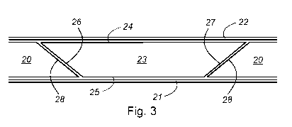
Fig. 3 shows a first embodiment of a wind turbine blade component integrated
into the
blade shell 11. The blade shell 11 comprises a sandwich structure with a
number of core
elements 20 arranged between an inner skin 21 defining an inner blade surface
and an
outer skin 22 defining an outer blade surface. Each skin 21, 22 includes a
number of
layers of a fibre material.
The wind turbine blade component is formed as a main laminate 23 joined to the
core
elements 20, wherein the inner and outer skins 21, 22 extend over a first side
24 and a
second side 25 of the wind turbine blade component, respctively. The wind
turbine blade
component further comprises a first edge 26 and a second edge 27. The main
laminate
23 is formed by a stack of layers extending in a thickness direction, as
indicated in fig. 6
to fig. 14. Each edge 26, 27 form an edge profile defined by the combined
local first and
second edges of each layer in the stack.
Here, the main laminate 23 has a trapezoid shaped cross-sectional profile,
wherein the
total width of the stack tapers from the first side 24 to the second side 25
seem in the
thickness direction. The first and second edges 26, 27 each form a tapered
edge profile
with an edge surface facing the adjacent core element 20. The adjacent core
element 20
CA 03073633 2020-02-21
WO 2019/043248 PCT/EP2018/073730
21
comprises an edge 28 having a tapered edge profile with an edge surface facing
the
main laminate 23. The opposite facing edges 26, 27, 28 together forms two
tapered joints
extending in opposite edgewise directions.
Fig. 4 shows a second embodiment of the wind turbine blade component, where
total
thickness of the wind turbine blade component tapers from one side 24, 25 to
the oppo-
site side 24, 25 seem in one edgewise direction. Here, the main laminate 23'
has a par-
allelogram shaped cross-sectional profile. The opposite facing edges 26', 27',
28' to-
gether forms two tapered joints extending in the same edgewise direction.
Fig. 5 shows the wind turbine blade component attached to an aerodynamic part
29 of
the blade shell 11. The core elements 20 are arranged to form a recess for
receiving the
main laminate 23", as illustrated. Here, the inner skin 21' extends along the
core ele-
ments 20 and further along the respective edges 28 and the outer skin 22 in
the recess.
The main laminate 23" is then laid up in the recess after curing of the
aerodynamic part
29. Once the main laminate 23" is laid up, the main laminate 23" is infused
with resin
and finally cured. The main laminate 23" may also be formed as a pre-cured
element
which is positioned in the recess and then attached to the aerodynamic part
29.
Fig. 6 shows a first embodiment of the stack comprising a first group 30 of
layers and a
second group 31 of layers arranged in a continuous order. The first and second
groups
30, 31 each comprise a number of layers of a fibre material. The first and
second groups
30, 31 of layers are arranged relative to each other. The stack defines a
total thickness
and a total width of the wind turbine blade component.
The first and second groups 30, 31 each comprise a first outermost layer 32
facing the
first side 24 and a second outermost layer 33 facing the second side 25. One
layer of
the first group 30 functions as a reference layer for offsetting the other
layers of the first
group 30. Similarly, one layer of the second group 31 functions as a reference
layer for
offsetting the other layers of the second group 31. Here, the first outermost
layers 32 of
each group 30, 31 are used as the reference layers which are further aligned
relative to
each other in thickness direction.
The local width offset 34 of each offset layer of the first group 30 is
continuously in-
creased from the first side 24 to the second side 25, as illustrated in fig.
6. Similarly, the
local width offset 34 of each offset layer of the second group 30 is
continuously increased
CA 03073633 2020-02-21
WO 2019/043248 PCT/EP2018/073730
22
from the first side 24 to the second side 25. Here, the local width offsets 34
in the first
group 30 are equal to the local width offsets 34 in the second group 31.
The individual layers of the first group 30 forms a first edge profile 35
defined by the
combined local first edges and local second edges. Similarly, individual
layers of the
second group 31 forms a second edge profile 36 defined by the combined local
first
edges and local second edges. Here, both the first and second edge profiles
extend in
the same edgewise direction, as illustrated in fig. 6.
Fig. 7 shows a second embodiment of the first group 30 and the second group
31,
wherein the layers of the second group 31 are offset in an opposite edgewise
direction
relative to the layers of the first group 30.
Here, the first outermost layer 32 of the second group 31 functions as the
reference layer.
The first outermost layer 32 of the second group 31 is further aligned in the
thickness
direction with the second outermost layer of the first group 30.
The local width offsets 34 in the first group 30 are equal to the local width
offsets 34 in
the second group 31, but in different directions. The first and second edge
profiles 35,
36' thus extend in opposite edgewise directions.
Fig. 8 shows a third embodiment of the first group 30 and the second group 31,
wherein
the second outermost layer 33 of the first group 30 functions as a reference
layer for
offsetting the individual layers of the second group 31. All layers of the
second group 31
are thereby be offset in the edgewise direction relative to the reference
layer, as illus-
trated in fig. 8.
Here, the first outermost layer 32 of the first group 30 functions as the
reference layer for
the other layers of the first group 30. Hence, a local width offset 34' exists
between the
two reference layers, as illustrated in fig. 8.
Here, the first outermost layer 32 of the second group 31 only partly overlaps
the second
outermost layer 33 of the first group 30. Whereas in fig. 7, the first
outermost layer 32 of
the second group 31 fully overlaps the second outermost layer 33 of the first
group 30.
Fig. 9 shows a fourth embodiment of the first group 30 and the second group
31, wherein
CA 03073633 2020-02-21
WO 2019/043248 PCT/EP2018/073730
23
the layers of the second group 31 are offset in an opposite edgewise direction
relative to
the layers of the first group 30.
The first outermost layer of the second group 31 functions as the reference
layer for
offsetting the other layers of the second group 31. Similarly, the first
outermost layer of
the first group 30 functions as the reference layer for offsetting the other
layers of the
first group 30. The two reference layers are here aligned in the thickness
direction.
Here, a greater local width offset 34" exits between the second outermost
layer 33 of the
first group 30 and the first outermost layer of the second group 31. Thereby,
further re-
ducing the overlap between these two outermost layers 32, 33.
Fig. 10 shows a fifth embodiment of the first group 30' and the second group
31', wherein
the number of layers in the first group 30' differ from the number of the
second group 31'.
Here, the number of the layers in the first group 30' is smaller than the
number of layers
in the second group 31'.
Alternatively or additionally, the reference layer of the second group 31' is
aligned with
an intermediate layer of the first group 30'. The first outermost layer of the
second group
31' thus partly overlaps the second outermost layer 33 of the first group 30'.
Fig. 11 shows a sixth embodiment of the first group and the second group,
wherein the
local width offsets of the first group 30 differ from the local width offsets
of the second
group 31.
Here, the layers of the first group 30 have a first local width offset 34a
measured relative
to its reference layer. The layers of the first group 30 form a first edge
profile 35" arranged
in a first angular position relative to the thickness direction.
Similarly, the layers of the second group 31 have a second local width offset
34b meas-
ured relative to its reference layer. The layers of the second group 31 form a
second
edge profile 36¨ arranged in a second angular position relative to the
thickness direction.
As indicated in fig. 11, the first local width offset 34a is greater than the
second local
width offset 34b. This difference in width offsets results in the first and
second edge
profiles 35", 36¨ being placed in different angular positions relative to the
thickness di-
rection. Whereas, the first and second groups 30, 31 of fig. 6 have equal
width offsets
and thus the first and second edge profiles 35, 36 thereof are placed in
parallel angular
CA 03073633 2020-02-21
WO 2019/043248 PCT/EP2018/073730
24
positions.
Fig. 12 shows a seventh embodiment of the first group 30 and the second group
31",
wherein the layers of the first group 30 and the layers of the second group
31" have
different local widths.
Here, all layers of the first group 30 have a first local width and all layers
of the second
group 31" have a second local width, as illustrated in fig. 12 and further in
figs. 17-18.
Each group 30, 31" of layers are continuously offset in a selected edgewise
direction to
form the desired first and second edge profiles 35, 36. Whereas in
conventional main
laminates, the layers are individually cut into different widths to form the
desired edge
profiles, such as disclosed in US 2009/0169392 Al.
Fig. 13 shows an eighth embodiment of the stack where the first group 30' of
layers and
the second group 31¨ of layers are arranged in an alternating order. Here, the
first outer-
most layer 32 of the second group 31¨ is arranged on top of the first
outermost layer 32
of the first group 30'. A subsequent layer of the first group 30' is arranged
on top of the
first outermost layer 32 of the second group 31". A subsequent layer of the
second group
31" is arranged on top of this subsequent layer of the first group 30', and so
forth.
Here, the layers within the first and second groups 30', 31¨ are offset in the
same overall
edgewise direction, preferably having equal local width offsets as illustrated
in fig. 6. The
first group 30' of layers is further offset in the edgewise direction relative
to the second
group 31¨ of layers, as illustrated, so the layers form partly overlapping
layers.
Here, the first and second groups 30', 31" form a stack with a parallelogram
shaped
cross-sectional profile. The total width of this stack is defined by the
combined local
widths of the partly overlapping layers. Further, the stack has a first side
24' defined by
the combined first outermost layers 32 of the first and second groups 30',
31¨. The sec-
ond side 25' is defined by the combined second outermost layers 33 of the
first and
second groups 30', 31". Here, the stack has a uniform overlap between
corresponding
layers of the first and second groups 30', 31¨, as illustrated.
The stack may thus be formed using layers having a narrower width than the
desired
total width by simply offsetting the layers within the first and/or second
group and further
offsetting the respective groups relative to each other.
CA 03073633 2020-02-21
WO 2019/043248 PCT/EP2018/073730
Fig. 14 shows a ninth embodiment of the first group 30' and the second group
31",
wherein the second group 31" of layers are offset in an opposite edgewise
direction
relative to the first group 30' of layers.
5
Here, the first and second groups 30', 31" form a stack with a trapezoid
shaped cross-
sectional profile. The total width of this stack is defined by the combined
local widths of
the partly overlapping layers. Further, the stack has a first side 24" defined
by the com-
bined first outermost layers 32 of the first and second groups 30', 31". The
second side
10 25" is defined by the combined second outermost layers 33 of the first and
second
groups 30', 31". Here, the stack has a minimum overlap between the second
outermost
layers 33 of the first and second groups 30', 31" and a maximum overlap
between the
first outermost layers 32 of the first and second groups 30', 31".
15 The lowermost layer of this stack, e.g. the first outermost layer 32 of
the first group 30',
functions as the reference layer for offsetting the other layers of the stack,
as illustrated
in fig. 14.
Here, the total width of the stack tapers from the second side 25" to the
first side 24" in
20 the thickness direction. However, the tapering direction may also be
reversed so that the
total width of the stack tapers from the first side 24" to the second side 25"
in the thick-
ness direction.
Fig. 15a-b show two alternative first embodiments of a wind turbine blade
component
25 formed as a main laminate 37, wherein both fig. 15a and fig. 15b show
the main laminate
37 having an overall cross-sectional profile formed by a number of sub-parts
38 arranged
relative to each other.
Here, the individual sub-parts 38 are arranged relative to each other in the
thickness
direction, as indicated in fig. 15a. Optionally, the individual sub-parts 38
are arranged
relative to each other in thickness direction and/or in the edgewise
direction, as indicated
in fig. 15b. Alternatively or additionally, the individual sub-parts 38 may
also be arranged
relative to each other in the lengthwise direction (not shown).
The first and second groups 30, 31 of layers described in relation to figs. 6-
14 form one
sub-part of the main laminate 37.
CA 03073633 2020-02-21
WO 2019/043248 PCT/EP2018/073730
26
Here, the first and second groups 30, 31 form one symmetrical half of the main
laminate
37, as illustrated in fig. 15b, while the other half 39 is formed by a
transformed copy of
the first and second groups 30, 31. The two halves are arranged relative to a
central line
40. The central line 40 extends between the first and second edges or the
first and sec-
ond sides of the main laminate 37. Alternatively, the main laminate 37
comprises four
symmetrical sub-parts, as illustrated in fig. 15b. The first and second groups
30, 31 form
one sub-part while the other three sub-parts 38' are formed by a transformed
copy of the
first and second groups 30, 31.
Here, the first and second groups 30, 31 form one sub-part where at least one
other sub-
part 38" is arranged relative to the first and second groups 30, 31. This sub-
part 38" has
a configuration that differs from the configuration of the first and second
groups 30, 31,
as illustrated in fig. 15a. The sub-part 38" is formed by a third group of
layers and a fourth
group of layers arranged in a continuous order or in an alternating order, as
illustrated in
figs. 6 and 13. Here, a sub-part 38" is arranged on both the first and second
sides 24,
of the first and second groups 30, 31.
Fig. 16a-b show two alternative second embodiments of the wind turbine blade
compo-
20 nent, wherein the main laminate 37' has a different overall cross-
sectional profile formed
by the individual sub-parts 38.
The first and second groups 30, 31 of layers may form one half of the main
laminate 37'
while the other half 39' has the same overall configuration, but different
dimensions, as
25 illustrated in fig. 16a. The other half 39' is formed by a third group
of layers and a fourth
group of layers arranged in a continuous order or in an alternating order. The
two halves
are arranged relative to a central line 40'.
Here, the layers of the third and fourth groups have a smaller local width
than the local
.. width of the first and second groups 30, 31 of layers. Thereby, forming a
narrower profile
that the layers of the first and second groups 30, 31. The other half 39' and
the first and
second groups 30, 31 of layers are arranged so that the total width of the
main laminate
37' continuously tapers along the thickness of the main laminate 37'.
One sub-part 38¨ is arranged at the second side 35 while another sub-part 38¨
is ar-
ranged at the first side 34 of the first and second groups 30, 31, as
illustrated in fig. 16b.
CA 03073633 2020-02-21
WO 2019/043248 PCT/EP2018/073730
27
Here, the layers of the groups forming said one sub-part 38¨ have a smaller
local width
than the local width of the first and second groups 30, 31 of layers. Thus,
the sub-part
38¨ has a narrower profile that the layers of the first and second groups 30,
31. Here,
the layers of the groups forming said another sub-part 38¨ have a greater
local width
than the local width of the first and second groups 30, 31 of layers. Thus,
the sub-part
38¨ has a wider profile that the layers of the first and second groups 30, 31.
Similar to the sub-parts 38" of fig. 15, the sub-parts 38¨, 38¨ optionally has
a relative
thickness smaller than the relative thickness of the sub-part formed by the
first and sec-
ond groups 30, 31.
Fig. 17 shows a tenth embodiment of the wind turbine blade component, wherein
the
respective groups of layers have different local lengths and different local
widths.
The layers of the first group 30 all have a first local length, L1, while the
layers of the
second group 31 all have a second local length, L2. Further, the layers of an
optional
third group 41 all have a third length, L3. Here, the layers of the first and
second groups
30, 31 of layers extend beyond the local length of the third group 41, thus
the first and
second lengths L1, L2 are greater than the third length L3. Furthermore, the
layers of the
first group 30 of layers extend beyond the local length of the second group
31, thus the
first length L1 is greater than the second length L2.
Further, the layers of the first group 30 all have a first local width, W1,
while the layers of
the second group 31 all have a second local width, W2. Further, the layers of
an optional
third group 41 all have a third width, W3. Here, the layers of the second and
third groups
31, 41 of layers extend beyond the local width of the first group 30, thus the
second and
third widths W2, W3 are greater than the first width W1. Furthermore, the
layers of the
third group 41 of layers extend beyond the local width of the second group 31,
thus the
third width W3 is greater than the second width W2.
As illustrated in fig. 17, the respective groups 30, 31, 41 are aligned
centrally relative to
a longitudinal central line (not shown) of the first group 30.
Fig. 18 shows an eleventh embodiment of the wind turbine blade component,
wherein
the respective groups of layers are offset towards the first or second edge
26, 27. Here,
the first, second and third groups 30, 31, 41 are offset towards the first
edge 26.
CA 03073633 2020-02-21
WO 2019/043248 PCT/EP2018/073730
28
Alternatively, the first, second and third groups 30, 31, 41 are offset
towards the second
edge 27.
In the embodiments of figs 17 and 18, the first, second and third groups 30,
31, 41 are
further be aligned relative to the first end 42, alternatively the second end
43. Alterna-
tively, the first, second and third groups 30, 31, 41 may be aligned centrally
relative to a
central edgewise central line (not shown).
Fig. 19 shows a twelve embodiment of the wind turbine blade component, wherein
the
individual layers of one group 30, 31, 41 are offset both in the lengthwise
direction and
in the edgewise direction. Thereby, forming a stack having a tapered profile
in both the
lengthwise and edgewise direction.
The individual layers may be continuously offset towards the second end 43 and
the
second edge 27. Alternatively, the individual layers may be offset towards the
first end
42 and/or the first edge 26.
Fig. 20 shows a thirteenth embodiment of the wind turbine blade component,
wherein
the individual layers of one group are offset in both the edgewise and
lengthwise direc-
tions while the individual layers of another group are offset only in the
edgewise direction.
Here, layers of the first group 30 are offset in both the edgewise and
lengthwise direc-
tions while the layers of the second or third group, 31, 41 are offset only in
the edgewise
direction. Alternatively, the layers of the second or third group, 31, 41 may
also be offset
in both the edgewise and lengthwise directions, but offset differently than
the layers of
the first group 30.
Here, the layers of the first group 30 have a greater local width than of the
layers of the
second or third group 31, 41. However, the layers of the second or third
group, 31, 41
may have the same local width as the layers of the first group 30.
Fig. 21 shows a fourteenth embodiment of the wind turbine blade component,
wherein
the respective groups 31, 41 are angular offset relative to the lengthwise
direction 44.
The layers of groups 31, 41 are angular offset towards the first edge 26,
alternatively
towards the second edge 27. The layers of the group 30 extend parallel to the
lengthwise
direction 44.
CA 03073633 2020-02-21
WO 2019/043248 PCT/EP2018/073730
29
Here, the total width increases uniformly from the first end 42 to the second
end 43.
Fig. 22 shows a fifteenth embodiment of the wind turbine blade component,
wherein the
respective groups 31, 41 extend in a curved direction towards the first edge
26, alterna-
tively towards the second edge 27.
The layers of the group 30 extend parallel to the lengthwise direction 44.
However, all
layers of the groups 30, 31, 41 may extend in the same curved direction.
Alternatively or additionally, the individual layers within one group 30, 31,
41 may be
arranged similarly to the embodiments shown in figs. 21 and 22.
The abovementioned embodiments may be combined in any combinations without
devi-
ating from the present invention.