Note: Descriptions are shown in the official language in which they were submitted.
I
A SIEVE DEVICE FOR FINE CLEANING OF
GRAINY MATERIAL
The object of the invention is a sieve device for fine cleaning of grainy
material, in
particular final fine cleaning of heavier contaminants after preliminary
removal of light
contaminants by an aspirator drawing air during gravitational falling of
grainy material.
From international publication of invention no. WO 2017/179999, belonging to
the
applicant of the present invention, there is a known aspirator for separating
and removing
light contaminants from grainy material, having a body, in whose upper part
there is an
air-drawing fan, and in the central part there is an axially mounted charging
hopper con-
nected to an inlet of grainy material, wherein in the lower part there is a
module in the form
of a centripetal guide consisting of a cylindrical housing, on whose inner
surface there are
guiding plates distributed uniformly at a certain distance from each other, in
various trans-
verse planes, with their ends facing the axis of the device, so that plates in
one plane are
offset relative to plates in the neighbouring plane. Between the charging
hopper and the
centripetal guide, constituting a separate module, there is a module in the
form of a cylin-
der, inside which there is a centrifugal guide having the form of an axial
bracket, on whose
surface there are guiding elements mounted in various transverse planes, with
their ends
facing the inner wall of the cylinder. A stream of grainy material falling
gravitationally
from the charging hopper is dispersed centrifugally or centripetally by the
guiding ele-
ments, which results in providing thorough and highly efficient purging of
light contami-
nants, which are drawn by the fan and directed outside, and the cleaned grainy
material is
directed gravitationally out of the lower outlet of the body. Unfortunately,
the aspirator
CA 3074454 2020-03-03
2
does not solve the problem of purging the grainy material of larger and
heavier contami-
nants, especially stones or shells. Flat, cylindrical or conical sieves,
usually mobile, pen-
dulous and vibrating or rotating, are used to remove this type of
contaminants. The sieves
are made of perforated sheet metal or a metal mesh, or of plastic, flat sieves
usually having
multiple levels. Sets of flat sieves are usually provided with a fan
generating a jet of air
upwards from under the lower sieve, which is supposed to remove lighter
contaminants
from sieve surfaces, as well as to restore openings in the sieves.
Alternatively or jointly,
the restoration of clogged openings uses shaking devices in the form of balls
or bars mov-
ing under the openings. The efficiency of cleaning grainy material in a set of
flat sieves
depends largely on the thickness of the layer of material on the sieve, the
shape and size
of openings in the sieve, the speed of material sliding on the sieve and the
length of the
sieve. Stationary flat sieves are cheap to produce and operate, with the speed
of sliding
being adjusted by the inclination of the sieve. Longer sieves allow more
thorough cleaning
of the material, but they prolong the cleaning process. When increasing the
angle of inch-
nation of the sieve, the sliding speed is increased and the layer of material
is reduced, while
obstruction of openings in the sieve may occur due to the grain having higher
kinetic en-
ergy, resulting in jumping upward through the edges of the openings. From US
patent no.
US 3370705 there is a known device for cleaning corn grain, having a two-
layered flat
sieve made of a plastic mesh, placed at an angle between the outlet of a
supplying conveyor
and an inlet into grain storage, wherein the angle of inclination can be
adjusted by means
of a vertical stand provided at various heights with openings with a lock. The
device is
provided with a vibrator and a fan, and scrapers removing contaminants
remaining after
the blowing are placed on the surface of the lower sieve. US patent no. US
4652362 in turn
presents a device for separating heavy contaminants, especially stones, from
grains and
other bulk goods by means of two flat, parallel, inclined vibrating tables in
the form of a
sieve with a layered construction, through which a stream of air is directed
from the lower
table towards the top, generally perpendicular to their surface. Light
contaminants are re-
moved from the upper table and heavier material is conveyed to the lower
table, where it
is separated into grain removed from the lower end of the table and stones
removed from
CA 3074454 2020-03-03
3
the upper end of the table. There is a known cleaner for cereals, corn,
rapeseed, sunflower
or legumes by the name of SEED 45, offered by the German RIELA company, where
the
cleaning process takes place on two flat sieves mounted at a small angle in
the body, the
upper sieve having perforation with openings larger than the lower sieve.
Material coarser
than the grain remains on the upper sieve and grain remains on the lower
sieve, while fine
contaminants pass through the lower sieve and are directed outside, all light
contaminants
being removed by means of an aspirator. Moreover, there are known cleaning
machines
from the Danish DAMAS company, intended for preliminary and main cleaning of
numer-
ous cereal species and seeds. For example, the VIBAM machine has a box with
flat sieves,
onto which the material is conveyed upon initial aspiration. The sieves are
used to remove
husks, shells, small seeds, weeds, sand as well as large and heavy
contaminants which
cannot be removed by means of airflow. In the box there are at least three
flat sieves
mounted at an angle, the upper and central sieves removing coarse
contaminants, larger
than the grain, and the lower sieve separating sand and fine weeds. A similar
rule was used
in the OMEGA machine, while the small UNISEED machine and the large DUOSEED
machine of this producer used a vibrating drive for the sieves. In all of the
abovementioned
machines the sieves are replaceable, and their selection depends on the size
and type of
grain, the restoration of obstructed openings in sieves taking place by means
of rubber
balls. A sieve in the form of a mat can be cleaned by the device known from US
patent no.
US 7416085, comprising shaking elements placed under the sieve mat, which
strike against
the bottom of the mat, cleaning it of the screened product obstructing the
openings, the
shaking elements being mounted on at least one elongated tight band, like a
rope or a tape,
which extends below the mat. The sieve surface is made of replaceable elements
which by
means of a frame protruding downwards surround the sieve mat on all sides,
while the
ends of the band are mounted on the frame of the sieve element, wherein the
shaking ele-
ments preferably constitute balls. There is also a known machine by the name
of LACA
for cleaning the grain of oil plants, manufactured by the German BOHLER
company. This
machine uses an arrangement of two flat sieves connected to a vibrator.
CA 3074454 2020-03-03
4
The objective of the present invention is to improve the efficiency of fine
cleaning,
in particular of heavy and large contaminants, of grainy material which has
been prelimi-
narily cleaned of light contaminants in an aspirator, in particular in the
aspirator presented
in publication no. WO 2017/179999.
The essence of the invention constitutes the construction of a sieve device
for fine
cleaning of grainy material after preliminary cleaning in an aspirator, having
an inclined
body made of separably integrated frames, in which replaceable stationary
sieves are
placed one below the other, the upper sieve having openings corresponding to
the size of
the grain, and the lower sieve having openings smaller than the grain, while a
charging
hopper is mounted in the upper, peripheral part of the body above the upper
sieve. Accord-
ing to the invention, each sieve consists of cascading identical flat sieve
segments con-
nected in sequence by z-shaped connectors, so that the planes of all sieve
segments are
parallel and above each z-shaped connector there is a set of plates mounted
pendulously
and independently on a bracket mounted on the frame of the body above the
sieve, parallel
to the z-shaped connector, the combined width of plates in the set
corresponding to the
width of the sieve segment. The body along with the sieves is inclined
relative to the
ground level at an angle no lower than 50 and no higher than 55 . Said body is
suspended
on the supporting construction of an aspirator by means of bands of adjustable
length, the
charging hopper being placed under the outlet of the aspirator. Preferably,
the device can
be provided with a beater mechanism striking cyclically against the body. The
location of
the brackets along with a set of plates relative to the sieve segments and
relative to z-
shaped connectors is adjustable. When fine-cleaning light grainy material of a
small size,
the plates at rest are positioned near the edge of a higher situated sieve
segment, and the
lower edge of the plates is away from the surface of a lower situated sieve
segment by a
distance of slightly less than the grain size. When fine-cleaning heavy grainy
material of a
large size, the lower edge of the plates at rest leans against the surface of
a lower situated
sieve segment. The ratio of the distance between the planes of adjacent sieve
segments to
the length of the sieve segment is no less than 0.03 and no more than 0.25,
while the ratio
of the length of the sieve segment to the width of the sieve segment is no
less than 0.25
CA 3074454 2020-03-03
5
and no more than 0.5. Due to such construction, completely clean grain is
achieved with
small financial expenses, since stationary sieves are cheap due to their
simplicity and easy
to operate.
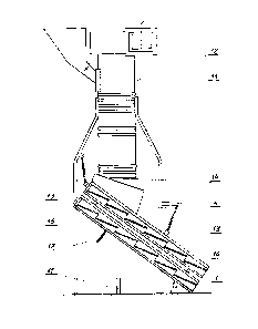
The device according to the invention is illustrated in an embodiment in the
draw-
ing, in which Fig. 1 presents schematically a complete body suspended under
the outlet of
an aspirator, Fig. 2 ¨ the body in a simplified view without a charging
hopper, and Fig. 3
¨ the body in a cross-section along the line of Fig. 2.
The body 1 consists of two identical frames 2 separably connected to each
other.
The upper sieve 3 having openings corresponding to the grain size is placed in
the upper
frame 2, and the lower sieve 3' having openings smaller than the grain is
placed in the
lower frame 2. The charging hopper 4 is mounted in the higher part of the body
1, above
the upper sieve 3. The upper sieve 3 consists of cascading identical flat
sieve segments 5
with openings corresponding to the grain size, and the lower sieve 3' consists
of identical
flat sieve segments 5' with smaller openings. The adjacent segments 5 and the
adjacent
segments 5' are connected to each other by a z-shaped connector 6, so that the
planes of
all sieve segments 5, 5' are parallel. Above each z-shaped connector 6 there
is a set of
plates 7 mounted pendulously and independently on a bracket 8 mounted on the
frame 2
of the body 1 above the sieve 3 and 3', parallel to the z-shaped connector
(6), the combined
width of the set of plates 7 corresponding to the width of the sieve segment
5, 5'. Each
plate 7 in the set is suspended on the bracket 8 by means of two circular
hangers 9. The
brackets 8 are mounted on the frames 2 by means of bolts 10, which enable both
raising
and moving the brackets 8 relative to the frame 2. The body 1 along with the
sieves 3, 3'
is suspended on the supporting construction 11 of the aspirator 12 by means of
bands 13
with an adjustable length, so that it is inclined relative to the ground at an
angle a ranging
from 50 to 550, the charging hopper 4 being placed under the outlet 14 of the
aspirator 12.
Next to the hopper 4, in the end of the upper frame 2 there is a flange 15
shielding against
accidentally dropped grain. Moreover, the frame 2 in its upper and lower part
has hooks
16 used to mount the bands 13. In order to facilitate the removal of grain
obstructing the
CA 3074454 2020-03-03
6
openings in the sieve 3 or contaminants in the sieve 3', it is possible to use
a beater mech-
anism 17 striking against the body 1 with the sieves 3, 3'. When fine-cleaning
light grainy
material of a small size, the plates 7 at rest are positioned near the edge of
the higher
situated sieve segment 5, 5', and the lower edge of the plates 7 is away from
the surface of
the lower situated sieve segment 5,5' by a distance of less than the grain
size, which allows
avoiding the blocking of light grain, for example grass grain, on the plates 7
when sliding
on the sieve segments 5, 5'. When fine-cleaning heavy grainy material of a
large size, the
lower edge of the plates (7) at rest leans against the surface of the lower
situated sieve
segment 5, 5', which allows cleaning of the sliding grain, for example corn,
with higher
efficiency. It has been determined empirically that a preferable result of
cleaning grainy
material can be achieved with a ratio of the distance d between the planes of
adjacent sieve
segments 5 or 5' to the length 1 of the sieve segment 5, 5' of no less than
0.03 and no more
than 0.25, and with the ratio of the length 1 of the sieve segment 5, 5' to
its width k of no
less than 0.25 and no more than 0.5.
The operation of the device is as follows: grainy material cleaned of light
contam-
inants in the aspirator 12 falls out of the outlet 14 directly into the
charging hopper 4 placed
on the body 1 suspended on the supporting construction 11, and when sliding on
the sieve
segments 5 with openings corresponding to the grain size, it passes onto the
lower sieve 3'
positioned below, with openings smaller than the grain size. After reaching
the edge of the
z-shaped connector 6 it encounters an obstruction in the form of a set of
plates 7, on which
it loses its kinetic energy, so that on the next segment 5 it begins its
travel with a zero
velocity, wherein the steadily moving grain cleans the obstructed openings.
Such a process
is repeated on each sieve segment 5, and only large contaminants remain at the
end of the
sieve 3, falling into a trough placed outside. A similar process is repeated
on the lower
sieve 3', except grain and fine heavy contaminants are present on sieve
segments 5', falling
through openings smaller than the grain below the sieve 3', and the grain
slides on the
subsequent segments 5' to be ultimately received via a conveyor in a
storehouse.
CA 3074454 2020-03-03