Note: Descriptions are shown in the official language in which they were submitted.
CA 03076035 2020-03-17
WO 2019/060421
PCT/US2018/051760
INTRACORONARY CHARACTERIZATION OF MICRO VASCULAR
OBSTRUCTION (MVO) AND MYOCARDIAL INFARCTION
CLAIM OF PRIORITY AND RELATED APPLICATIONS
[0001] This application claims the benefit of and priority to U.S.
Provisional Patent Application Ser. No. 62/560,545 filed on September 19,
2017,
entitled INTRACORONARY VASCULAR RESISTANCE AND OTHER
PARAMETERS TO CHARACTERIZE MICRO VASCULAR OBSTRUCTION
(MVO) AND MYOCARDIAL INFARCTION DURING CORONARY
REPERFUSION, which is hereby incorporated by reference in its entirety. This
application also incorporates by reference the entirety of the subject matter
disclosed in U.S. Patent Application 15/398,470, filed January 4, 2017, and
published as U.S. Patent Application Pub. No. 2017/0189654 Al published on
July 6, 2017.
TECHNICAL FIELD
[0002] Methods and devices for the diagnosis and treatment of
microvascular obstruction (MVO) and other dysfunctional diseases of the
microvasculature of many organs including the heart.
BACKGROUND
[0003] Heart attack or STEMI (STEM' defined as acute ECG ST
segment myocardial infarction) is caused by sudden occlusion of an epicardial
coronary artery, typically by fibrin and platelet rich clot, with associated
and
embolic plaque and debris. Electrocardiographic signs of acute transmural
myocardial infarction (heart attack) are ECG tracings with ST segment
elevation
(STEMI). ST segment elevation is a hallmark of severe coronary artery
narrowing, often with occlusion causing ongoing ischemic myocardial injury
with cell death. Large vessel occlusion is often associated with small vessel
or
stenosis occlusion (termed microvascular occlusion or MVO) by clot and
embolic debris is also a serious problem since the heart muscle is deprived of
blood, oxygen, and critical nutrients necessary to sustain cell life.
1
CA 03076035 2020-03-17
WO 2019/060421
PCT/US2018/051760
[0004] Interventional cardiology is very proficient at opening
severely
narrowed or occluded epicardial coronary arteries in the cardiac
catheterization
laboratory using catheters, guide wires, balloons, and stents. However,
microvascular obstruction cannot be diagnosed in the catheter lab, and more
importantly MVO cannot be treated even if/when it could be accurately
diagnosed.
[0005] Heart muscle salvage (saving muscle from death due to lack of
blood and oxygen) is a critical concern to ensure good long-term outcomes in
patients suffering STEMI. A key component of good long-term outcome
involves minimizing the time between coronary artery occlusion (at home or
outside the hospital) and opening the occluded artery in the catheter lab.
Interventional cardiologists can reduce artery occlusion time by implementing
streamlined and efficient emergency medical systems whose goal is to have
STEMI patients arrive in catheterization laboratory as soon as possible,
avoiding
long term STEMI complications. Complications resulting from STEMI and
MVO include, systolic and diastolic heart failure, arrhythmias, aneurysms,
ventricular rupture and multiple other serious complications. These
complications can markedly shorten life and impose severe limitations on
quality
of life.
[0006] Modern interventional therapy for acute myocardial infarction has
matured over time with impressive clinical results. Heart attack/STEMI death
rates at 30 days have dropped from more than 30% to less than 5%, achieved by
reperfusing the heart with blood as soon as possible during coronary arterial
occlusion. This goal is accomplished by streamlining clinical care systems to
open coronary arteries in the catheterization lab as rapidly as possible after
heart
attack onset. Emergency procedures including stenting and balloon angioplasty
are undisputed as necessary for improving early and late clinical results of
acute
heart attack therapy.
[0007] However, substantial challenges remain for treating STEMI
patients and reducing long term complications. These problems include heart
failure (poor cardiac function and cardiac enlargement), cardiac/ventricular
rupture, persistent ischemic chest pain/angina, left ventricular aneurysm and
clot,
and malignant arrhythmias.
2
CA 03076035 2020-03-17
WO 2019/060421
PCT/US2018/051760
[0008] Late Heart failure complicates 25-50% of acute STEMI, caused
by poor left ventricular function and damaged myocardium. Heart failure is
worsened as the heart remodels in shape and size, and loses function. Nearly
half
of all new heart failure in patients under 75 years is linked to STEMI.
[0009] Many years investigating STEMI therapy show that opening the
epicardial/large coronary artery is insufficient to salvage heart muscle and
optimize long term patient outcome. The most common reason for poor late
results after heart attack is microvascular obstruction (MVO). MVO is
occlusion
or severe flow limitation in the internal cardiac microvessels, typically by
clot.
These microvessels are impervious to stenting and conventional thrombolytic
therapy. Thus, despite a widely patent epicardial coronary artery, residual
MVO
obstructs blood flow into the heart causing cell ischemia death from severe
heart
muscle damage.
[0010] MVO thus remains a critical frontier in cardiology. Cardiac
microvessels comprise small arteries, arterioles, capillaries and venules
which
are frequently filled with clot and debris (platelets, fibrin, and embolic
plaque
material) during STEMI. Too often, obstructed microvessels (MVO) do not
resolve even after stent placement, and have serious long-term negative
prognostic implications.
[0011] MVO is very common in STEMI patients, even though stenting
and balloon angioplasty are successful at opening epicardial coronary
arteries.
MVO occurs in more than half of all STEMI patients, even with good blood
flow through open epicardial arteries and newly placed stents.
[0012] MVO extent is key to the severity of myocardial damage and
patient outcome. MVO is best imaged via cardiac MRI which measures MVO
location, extent and severity. Mill, however, cannot be performed emergently
or
during a cardiac catheterization procedure since it requires patients to be in
a
separate imaging area and within a separate scanner.
[0013] Important features of MVO may be summarized by the following:
[0014] 1. MVO and microvascular dysfunction in STEMI is the principal
cause of major complications early and late after heart attack.
[0015] 2. Angiographic "no-reflow" or "low-reflow" is caused by MVO
and is due to obstructed microvessels within the heart. MVO is
fluoroscopically
3
CA 03076035 2020-03-17
WO 2019/060421
PCT/US2018/051760
characterized by very slow X-ray contrast filling the epicardial coronary
arteries
as visualized during coronary treatment in the catheterization laboratory.
[0016] 3. MVO causes myocardial cell injury and death from prolonged
ischemia/lack of oxygen, blood, and key metabolic nutrients such as glucose.
MVO microscopic analysis shows microvessels filled with platelet and fibrin
clot, dead myocardial cells, inflammatory cells, myocyte cell death, and
endothelial cell death along the obstructed intramyocardial capillaries.
[0017] 4. MVO studied acutely shows cardiac arterioles and
capillaries
completely occluded by platelet and fibrin-rich thrombus, platelet-neutrophil
aggregates, dying blood cells and embolic debris.
[0018] 5. When MVO complicates acute STEMI/myocardial infarction,
far greater heart/myocardial damage occurs, and poor ventricular function
occurs
early.
[0019] 6. MVO is very common. It occurs in:
[0020] a. 53% of all STEMI and NSTEMI regardless of epicardial flow,
[0021] b. 90% of Large Transmural STEMI,
[0022] c. 40% of MI with TIMI III (normal) X-ray visualized flow, and
[0023] d. MVO is the single most potent prognostic marker of events
after controlling for infarct size.
[0024] 7. Patients with microvascular obstruction have more late major
adverse cardiovascular events (MACE) than those without MVO (45% versus
9%).
[0025] 8. MVO is the best predictor of acute and chronic
cardiovascular
adverse outcomes.
[0026] 9. MVO acutely becomes late fibrous scar and causes poor
cardiac function.
[0027] MVO cannot be diagnosed in a conventional catheterization
laboratory. Moreover, no effective conventional therapies were available. Many
possible prior therapies all proved essentially ineffective, and in some
cases,
dangerous.
[0028] Problems encountered with prior MVO therapy include rapid
fluid bolus injection with drugs. This failure is best understood as fluids
follow
paths of least resistance. MVO-obstructed vessels have very slow flow, with
4
CA 03076035 2020-03-17
WO 2019/060421
PCT/US2018/051760
very high hydraulic resistance. Direct drug bolus into coronary arteries has
little
effect against MVO because the injected agent enters only open and
unobstructed microchannels, with little or none entering obstructed
microvessels
in STEMI. Studies suggest that only 1/1000 of a locally injected drug enters
obstructed microvessels, most drug entering the open and unobstructed
microvessels. Delivering high drug doses to occluded microchannels in this
adverse ratio yields unacceptably high toxic systemic drug level because all
injected drug eventually enters the systemic circulation. High systemic drug
levels place patients at risk of dangerous systemic bleeding and other
systemic
complications including vessel dissection due to high flow infusion rates.
[0029] Solving MVO is a critical need for cardiologists. Technology
and
methods to successfully and efficiently deliver therapeutic agents to MVO-
obstructed microvessels of multiple organs (Heart, brain, bowel, extremities,
liver, and kidneys for example) are not available. Such therapy must be
simple,
efficient, safe, and easy to use in the catheterization lab. Such methods must
deliver high dose therapeutic agents into occluded channels without causing
toxic systemic concentrations, and to be available to treat microvessels after
flow
restoration will permit a further goal of preventing or limiting reperfusion
injury.
[0030] There is a need in the art for apparatus and methods that can
measure real-time intracoronary vascular resistance (RTIVR) and compliance to
diagnose and treat microvascular obstruction (MVO) and tissue
necrosis/infarction.
SUMMARY
[0031] Methods and devices for the diagnosis and treatment of
microvascular obstruction (MVO) and other dysfunctional diseases of the
microvasculature of many organs including the heart. More particularly, non-
limiting embodiments include novel devices and methods to successfully
diagnose, restore patency, open and preserve flow, and limit reperfusion
injury
in organs and cases with microvascular obstruction. No known prior art methods
are available to detect and measure or treat MVO in real time during scenarios
such as invasive angiographic/therapeutic procedures. Such procedures include
therapy for organ systems including the heart (acute myocardial infarction -
5
CA 03076035 2020-03-17
WO 2019/060421
PCT/US2018/051760
primary percutaneous coronary intervention (PPCI)), brain (stroke (CVA), bowel
ischemia/infarction, pulmonary emboli/infarction, critical limb
ischemia/infarction, renal ischemia/infarction, and others. Using methods of
the
invention, a system comprising specialized infusion and sensing catheter,
diagnostic agents, therapeutic agents, and control console with specialized
algorithms can both diagnose and treat MVO by eliminating the microvascular
clot and debris causing the obstruction. The techniques involve a combination
of
novel devices, methods, and software to simultaneously diagnose and treat
MVO. This permits operation in real-time with real-time operator feedback for
diagnostic and therapeutic decision making, and so create a system feasible
for
interventional procedures.
BRIEF DESCRIPTION OF THE DRAWINGS
[0032] The present disclosure is illustrated by way of example and
not
limitation in the figures of the accompanying drawings, in which like
references
indicate similar elements and in which:
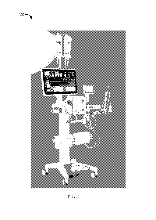
[0033] FIG. 1 illustrates an example of a modular computerized
diagnostic and infusion system for coronary and other human/animal
vasculature; in accordance with some embodiments of the present subject
matter;
[0034] FIG. 2 illustrates an example of an infusion catheter having an
occlusion balloon, in accordance with some embodiments of the present subject
matter;
[0035] FIG. 3 illustrates an example of an infusion catheter having
an
occlusion balloon, in accordance with some embodiments of the present subject
matter;
[0036] FIG. 4 illustrates a graph of an occlusion and infusion
algorithm,
in accordance with some embodiments of the present subject matter;
[0037] FIG. 5 illustrates a graph calculating real-time intracoronary
vascular resistance, in accordance with some embodiments of the present
subject
matter;
[0038] FIG. 6 illustrates a photographic slide of porcine non-
clinical
trials showing angiographic no-reflow after a 90 minute left anterior
descending
6
CA 03076035 2020-03-17
WO 2019/060421
PCT/US2018/051760
artery (LAD) occlusion distal to the second diagonal, in accordance with some
embodiments of the present subject matter;
[0039] FIG. 7 illustrates a photographic slide of porcine non-
clinical
trials showing a two chamber hi-resolution gadolinium enhanced magnetic
resonance imaging (MRI) scan with microvascular obstruction (MVO), in
accordance with some embodiments of the present subject matter;
[0040] FIG. 8 illustrates a photographic slide of porcine non-
clinical
trials showing platelet rich MVO in a 200 micrometer vessel, in accordance
with
some embodiments of the present subject matter;
[0041] FIG. 9A illustrates a photographic slide of porcine non-clinical
trials showing a four chamber magnetic resonance imaging (MRI) scan with
microvascular obstruction (MVO), in accordance with some embodiments of the
present subject matter;
[0042] FIG. 9B illustrates a photographic slide of porcine non-
clinical
trials showing a two chamber magnetic resonance imaging (MRI) scan with
microvascular obstruction (MVO), in accordance with some embodiments of the
present subject matter;
[0043] FIG. 10 illustrates a graphical representation of the MVOs
location shown in FIGS. 9A-B, in accordance with some embodiments of the
present subject matter;
[0044] FIG. 11 illustrates a graph of porcine non-clinical trials
showing a
percentage of MVO and a percentage of infarct size of the total left
ventricle, in
accordance with some embodiments of the present subject matter;
[0045] FIG. 12 illustrates a table comparing results of a porcine non-
clinical trial to human data, in accordance with some embodiments of the
present
subject matter;
[0046] FIG. 13 illustrates a table showing results of consecutive
animals
in a porcine non-clinical trial to create human like MVO, in accordance with
some embodiments of the present subject matter;
[0047] FIG. 14 illustrates an angiogram of a porcine non-clinical trial
showing results of test subject number fourteen, in accordance with some
embodiments of the present subject matter;
7
CA 03076035 2020-03-17
WO 2019/060421
PCT/US2018/051760
[0048] FIG. 15 illustrates an angiogram of a porcine non-clinical
trial
showing results of test subject number fourteen, in accordance with some
embodiments of the present subject matter;
[0049] FIG. 16 illustrates data from Mill hi-resolution scans of a
porcine
non-clinical trial, in accordance with some embodiments of the present subject
matter;
[0050] FIG. 17 illustrates position of histology sectioning blocks
from
the endocardial to epicardial border from section 1 of test subject 12 as
shown in
photographic slides in FIGS. 18-20 of a porcine non-clinical trial, in
accordance
with some embodiments of the present subject matter;
[0051] FIG. 18 illustrates a photographic slide of histology section
1,
block 1 of a porcine non-clinical trial, in accordance with some embodiments
of
the present subject matter;
[0052] FIG. 19 illustrates a photographic slide of histology section
1,
block 2 of a porcine non-clinical trial, in accordance with some embodiments
of
the present subject matter;
[0053] FIG. 20 illustrates a photographic slide of histology section
1,
block 5 of a porcine non-clinical trial, in accordance with some embodiments
of
the present subject matter;
[0054] FIG. 21 illustrates a photographic slide of a histology section
block 8 from test subject 8 of a porcine non-clinical trial, in accordance
with
some embodiments of the present subject matter;
[0055] FIG. 22 illustrates a photographic slide of a histology
section
block 8 from test subject 3 of a porcine non-clinical trial, in accordance
with
some embodiments of the present subject matter;
[0056] FIG. 23A illustrates a photographic slide of a histology
section
block 8 from test subject 3 of a porcine non-clinical trial, in accordance
with
some embodiments of the present subject matter;
[0057] FIG. 23B illustrates an example of the MVO occurrence
illustrated in FIG. 22 and FIG. 23A, in accordance with some embodiments of
the present subject matter;
[0058] FIG. 24 illustrates a photographic slide of a human histology
section, in accordance with some embodiments of the present subject matter;
8
CA 03076035 2020-03-17
WO 2019/060421
PCT/US2018/051760
[0059] FIG. 25 illustrates a graph showing faster pressure drops in
infarcted myocardium due to loss of capacitance produced with data from a
porcine non-clinical trial, in accordance with some embodiments of the present
subject matter;
[0060] FIGS. 26A-B illustrate charts comparing Tau and Tau40
calculations without heart rate compensation from a porcine non-clinical
trial, in
accordance with some embodiments of the present subject matter;
[0061] FIGS. 27A-B illustrate charts comparing Tau* and Tau40*
calculations with heart rate compensation from a porcine non-clinical trial,
in
accordance with some embodiments of the present subject matter;
[0062] FIG. 28 illustrates a chart comparing waterfall pressure at
Ti, T2,
and T3 from a porcine non-clinical trial, in accordance with some embodiments
of the present subject matter;
[0063] FIG. 29 illustrates a chart graphing real time vascular
resistance
from a porcine non-clinical trial, in accordance with some embodiments of the
present subject matter;
[0064] FIG. 30 illustrates a chart graphing mean values of real time
vascular resistance from a porcine non-clinical trial in 7 subjects, in
accordance
with some embodiments of the present subject matter; and
[0065] FIGS. 31A-B illustrate a chart graphing statistical significant
difference across 7 subjects of real time vascular resistance from a porcine
non-
clinical trial with statistical significant difference for every flow infusion
value,
in accordance with some embodiments of the present subject matter.
SUMMARY
[0066] Systems and apparatus are included that are configured to
determine in real time effectiveness of apparatus and methods used to unblock
microvascular obstructions (MVO). Because the results are shown in real time,
apparatus and methods can be quickly changed to alter treatment and more
quickly unblock or improve MVO. An infusion system using the occlusion
balloon blocks antegrade flow for a short time and measures vascular pressure
response as an infusate is infused in stepwise fashion at increasingly higher
flowrates. During antegrade flow occlusion a calculation of the real-time
9
CA 03076035 2020-03-17
WO 2019/060421
PCT/US2018/051760
vascular resistance can be made using the formula R(t) = P(t)/Qmean(t) where:
Qmean(t): is the flow mean values generated by the infusion system; P(t): is
the
distal pressure response in the vessel generated from the flow infusion; and
R(t):
is the calculated vascular resistance using the two other known parameters.
Examples of the described invention herein may be used for coronary and other
human vasculature to diagnose and treat microvascular obstruction (MVO) and
tissue necrosis/infarction.
[0067] The following disclosure outlines an approach and non-clinical
data generated from using this approach to measure RTIVR. The data show the
ability of systems/devices/methods described herein to measure RTIVR, Tau and
Waterfall Pressure and that these parameters can detect MVO and tissue
necrosis/infarction.
[0068] This Summary is an overview of some of the teachings of the
present application and not intended to be an exclusive or exhaustive
treatment
of the present subject matter. Further details about the present subject
matter are
found in the detailed description and appended claims. The scope of the
present
invention is defined by the appended claims and their legal equivalents.
DETAILED DESCRIPTION
[0069] The following detailed description of the present subject matter
refers to subject matter in the accompanying drawings which show, by way of
illustration, specific aspects and embodiments in which the present subject
matter may be practiced. These embodiments are described in sufficient detail
to enable those skilled in the art to practice the present subject matter.
References to "an", "one", or "various" embodiments in this disclosure are not
necessarily to the same embodiment, and such references contemplate more than
one embodiment. The following detailed description is demonstrative and not to
be taken in a limiting sense. The scope of the present subject matter is
defined
by the appended claims, along with the full scope of legal equivalents to
which
such claims are entitled.
[0070] The present subject matter provides devices, systems and
methods for unique techniques for measuring RTIVR to diagnose and treat
microvascular obstruction (MVO) and tissue necrosis/infarction. This
CA 03076035 2020-03-17
WO 2019/060421
PCT/US2018/051760
application also incorporates by reference the entirety of the subject matter
disclosed in U.S. Patent Application 15/398,470, filed January 4, 2017, and
published as U.S. Patent Application Pub. No. 2017/0189654 Al published on
July 6, 2017 ("the '470 Application"). The apparatus and methods described in
this application include but are not limited to the apparatus and methods
described in the '470 Application.
[0071] FIG. 1 illustrates an example of a modular computerized
diagnostic and infusion system 100 (hereinafter "infusion system") for
coronary
and other human/animal vasculature; in accordance with some embodiments of
the present subject matter. The infusion system 100 can be a clinical ready
modular system and can be configured in a mobile console form. The infusion
system 100 enables MVO diagnosis by at least one or more of the following:
= real-time coronary artery pressure and flow;
= pressure/resistance time parameters;
= Waterfall Pressure or Coronary Wedge Pressure;
= intracoronary electrocardiogram (ECG); and/or
= fractional flow reserve (FFR) measurements.
[0072] The infusion system 100 can enable MVO therapy by at least one
or more of the following:
= infusion of approved agent(s);
= targeted and low flow infusion; and/or
= continuous monitoring of diagnostic parameters.
[0073] FIG. 2 illustrates an example 200 of an infusion catheter
having
an occlusion balloon, balloon markers and infusion lumen in accordance with
some embodiments of the present subject matter. FIG. 3 illustrates an example
300 of an infusion catheter having an occlusion balloon placed over a 0.014"
pressure measuring guide wide in a rapid-exchange (RX) fashion, in accordance
with some embodiments of the present subject matter. The infusion catheters as
shown in FIGS. 2-3 can be used in systems/devices/methods described herein to
occlude a desired vessel, infuse desired fluids and measure pressure inside
the
vessel in real time and distal to the occlusion balloon. The infusion
catheters as
shown in FIGS. 2-3 can include: a 6F guide sheath compatible catheter, a
11
CA 03076035 2020-03-17
WO 2019/060421
PCT/US2018/051760
compliant 5x10mm occlusion balloon, and can be received over 0.014" pressure
guide wire. The infusion catheters as shown in FIGS. 2-3 can include a wide
flow infusion range, for example, 5-50 ml/min and can include axial flow
infusion. A person of skill would appreciate that catheter dimensions,
configurations, and infusion ranges may vary and remain within the scope of
the
present subject matter.
[0074] In some embodiments, the catheter can be inserted into a
myocardial vessel supplying blood to a patient's myocardium. In some
embodiments, the myocardial vessel or nearby vessels may or may not include
MVO or and may or may not include myocardial infarction. The catheter can
block antegrade blood flow within the myocardial vessel around the catheter by
inflating a balloon. In some embodiments, the myocardial vessel can include a
stent and the catheter can block antegrade blood flow from within the stent,
by
inflating a balloon.
[0075] FIG. 4 illustrates a graph 400 of an occlusion and infusion
algorithm, in accordance with some embodiments of the present subject matter.
In some embodiments, systems/devices/methods described herein can include an
infusion algorithm. The infusion algorithm can be generated by modular
computerized infusion system 100 such as is shown in FIG. 1. The infusion
system 100 can measure the native coronary blood pressure distal to the
occlusion balloon while the vessel is not occluded. At vessel occlusion, the
infusion system 100 can measures the time (Tau-) and pressure parameters for
the pressure drop-off In graph 400, the measurement of Tau- is shown at 401.
The infusion system 100 can measure the waterfall pressure (WFP) or coronary
wedge pressure (CWP) when these values are stable. In graph 400, the
measurement of WFP is shown at 402. In some embodiments, the infusion
system 100 then infuses saline or ringer solution in a step-wise fashion. In
this
example the flow is increased stepwise from 0 ml/min to 5, 10, 20, 30 and 40
ml/min and holds each flow value for 15 seconds. After the last flow infusion
of
40 ml/min, the flow is stopped and the pressure drop off called Tau40- is
measured. After the Tau40-, the WFP and CWP are measured again, the balloon
is deflated and antegrade blood flow re-established. The pressures, numbers of
steps, and times of infusion can be varied without changing the intention of
the
12
CA 03076035 2020-03-17
WO 2019/060421
PCT/US2018/051760
present disclosure. In graph 400, measurements of the stepwise pressure
increases are shown at 403 and 404. In graph 400, measurement of Tau40- is
shown at 405.
[0076] In some embodiments, Tau- can be described as the time it
takes
for the exponential intracoronary. blood pressure decay after native vessel
occlusion. In some embodiments, infusion system 100 vascular resistance
diagnostic sequence can include: room temperature ringer solution infusion in
5
steps, 5, 10, 20, 30 and 40 ml/min (15 sec each; 26.25 ml total). In some
embodiments, increasing pump flow can drive distal pressure and enable
infusion system 100 vascular resistance calculation: R= P/Q. In some
embodiments, Tau40- can be described as the time it takes for the exponential
intracoronary ringer pressure decay after stop of 40 ml/min ringer infusion.
[0077] FIG. 5 illustrates a graph 500 of calculating real-time
intracoronary vascular resistance, in accordance with some embodiments of the
present subject matter. In graph 500, measurements of pressure decay (Tau),
Waterfall Pressure (WFP) or Coronary Wedge Pressure (CWP) and real-time
intracoronary vascular resistance are shown. FIG. 5 shows how the real-time
intracoronary vascular resistance is calculated using the infusion algorithm
described below. In FIG. 5, the pump flow is a dotted line denoted as 501, the
distal pressure is a lighter gray line denoted as 502 and the vascular
resistance is
a dark line denoted by 503. In some embodiments, systems/devices/methods
described herein can include the following:
[0078] As the flow increases over the steps 0 ml/min to 5, 10, 20, 30
and
40 ml/min the infusion system 100 calculates the real-time vascular resistance
using the formula R(t)= P(t)/Qmean(t) where:
= Qmean(t) is the flow mean values generated by the infusion system,
= P(t) is the distal pressure response in the vessel generated from
the flow infusion, and
= R(t) is the calculated vascular resistance using the two other
known parameters.
[0079] In some embodiments, systems/devices/methods described herein
can provide that as the flow increases the vascular resistance drops off and
the
13
CA 03076035 2020-03-17
WO 2019/060421
PCT/US2018/051760
vascular resistance reaches a minimum plateau around the normal coronary flow
of 30-40 ml/min. In some embodiments, systems/devices/methods described
herein can provide that the largest change in the vascular resistance occurs
at
low flow values most likely caused by a "diode" effect as smaller flow values
are not sufficient to open up the coronary microcirculation.
[0080] In some embodiments, the capacitance seen in the pressure-flow
dynamics within a cardiac vessel can be related to elastance of the heart
muscle
itself as well as elastance of the capillary/microvasculature. In some
embodiments, the capacitance can include substantial diagnostic function
related
to myocardial structure and fibrosis of the cardiac skeleton. In some
embodiments, this function can be an important clinical implication.
[0081] FIGS. 6-31 relate to an MVO model developed using
embodiments described above to measure coronary vascular resistance. In some
embodiments, the MVO model can be used in an in vitro fashion or in humans or
animals. In some embodiments, FIGS. 6-31 relate to a porcine non-clinical MVO
model developed using embodiments described above to measure coronary
vascular resistance. In some embodiments, systems/devices/methods described
herein can provide a porcine occlusion-reperfusion model which generates a
consistent degree of MVO as found in humans. In these non-clinical trials the
MVO was 2.34 1.07% of the total left ventricle which is consistent with human
findings. In some embodiments, it has been shown that the model does not
generate micro-thrombi due to the use of heparin anticoagulation. In some
embodiments, it has been shown that low-dose heparin experiments generate
micro-thrombi. In some embodiments, it has been shown that MVO is not being
generated in test subjects with high collateralization.
[0082] The present non-clinical MVO model includes
systems/devices/methods described herein that provide that MVO was created in
a consecutive series of 15 animals at the University of Zurich/ETH.
[0083] In an example method:
= n= 15 (total series n= 23)
= 57 kg (50 ¨ 74 kg) pigs
14
CA 03076035 2020-03-17
WO 2019/060421
PCT/US2018/051760
= Heparinized w/ ACT> 150, open chest for defibrillation w/
preloaded amiodarone.
= 90min LAD occlusion with an infusion catheter such as shown in
FIGS 2-3 having an occlusion balloon distal to the 2nd diagonal.
= All pressure measurements completed without nitrates.
= Reperfusion for 6h before gadolinium contrast enhanced MRI
scan.
[0084] Measurements and imaging used:
= Procedural angiograms.
= Full infusion system parameters (Tau, WFP and real-time
resistance) at three time points (n= 7):
= Ti: before vessel occlusion;
= T2: after 90min occlusion and 10min reperfusion; and
= T3: after total of 4h (240min) of reperfusion before transport to
the MRI.
= Continuous pressure wire recordings using an example pressure
guidewire.
= Intracoronary ECG measurements over the pressure guidewire.
= MRI scans: Full functional imaging; Early and late gadolinium
enhanced imaging; Hi resolution imaging in perfused non-beating hearts
in >5 subjects.
= Histology of core infarct and border zone; detailed histology in
selected subjects.
[0085] FIG. 6 illustrates a photographic slide 600 of porcine non-
clinical
trials showing angiographic no-reflow after a 90 minute left anterior
descending
artery (LAD) occlusion distal to the second diagonal, in accordance with some
embodiments of the present subject matter. FIG. 7 illustrates a photographic
slide 700 of porcine non-clinical trials showing a two chamber hi-resolution
gadolinium enhanced magnetic resonance imaging (MRI) scan with
microvascular obstruction (MVO), in accordance with some embodiments of the
present subject matter. The MVO 702 has been circled in white. FIG. 8
illustrates a photographic slide 800 of porcine non-clinical trials showing
platelet
CA 03076035 2020-03-17
WO 2019/060421
PCT/US2018/051760
rich MVO in a 200 micrometer vessel, in accordance with some embodiments of
the present subject matter.
[0086] FIG. 9A illustrates a photographic slide 900 of porcine non-
clinical trials showing a four chamber magnetic resonance imaging (MRI) scan
with microvascular obstruction (MVO), in accordance with some embodiments
of the present subject matter. FIG. 9B illustrates a photographic slide 902 of
porcine non-clinical trials showing a two chamber magnetic resonance imaging
(MRI) scan with microvascular obstruction (MVO), in accordance with some
embodiments of the present subject matter. In the porcine non-clinical trial
MVO
was generated in 14 of the 15 subjects and the MRI %MVO corresponds with
human findings in large clinical trials. FIG. 10 illustrates a graphical
representation 1000 of the MVOs location shown in FIGS. 9A-B, in accordance
with some embodiments of the present subject matter. The graphical
representation shows the MVO at the basal 1001, midventricular 1002, apical
1003, and apex 1004 positions.
[0087] FIG. 11 illustrates a graph 1100 of porcine non-clinical
trials
showing a percentage of MVO and a percentage of infarct size of the total left
ventricle, in accordance with some embodiments of the present subject matter.
FIG. 12 illustrates a table 1200 comparing results of a porcine non-clinical
trial
to human data, in accordance with some embodiments of the present subject
matter. FIG. 13 illustrates a table 1300 showing results of consecutive
animals in
a porcine non-clinical trial to create human like MVO, in accordance with some
embodiments of the present subject matter.
[0088] FIG. 14 illustrates an angiogram 1400 of a porcine non-
clinical
trial showing results of test subject number fourteen in the left anterior
descending (LAD) coronary artery, in accordance with some embodiments of the
present subject matter. In test subject number fourteen there was no infarct
or
MVO created due to substantial collateralization. FIG. 15 illustrates an
angiogram 1500 of a porcine non-clinical trial showing results of test subject
number fourteen at LAD with a balloon occlusion, in accordance with some
embodiments of the present subject matter.
16
CA 03076035 2020-03-17
WO 2019/060421
PCT/US2018/051760
[0089] FIG. 16 illustrates data 1600 from MRI hi-resolution scans of
a
porcine non-clinical trial, in accordance with some embodiments of the present
subject matter. Pertinent MVO information is circled in white at 1601.
[0090] FIG. 17 illustrates position 1700 of histology sectioning
blocks
from the endocardial to epicardial border from section 1 of test subject 12 as
shown in photographic slides in FIGS. 18-20 of a porcine non-clinical trial,
in
accordance with some embodiments of the present subject matter. In summary,
the sectioning slides show the region immediately proximal to MVO: minimal
histological changes (scattered degenerated myofibres) and no evidence of
thrombosis. MVO region: Minimal to moderate myocardial
degeneration/necrosis with capillary congestion and endothelial swelling. No
evidence of thrombosis. As shown in FIG. 17, From each block: a) first section
from inner endocardial to epicardial surface; b) blank section every 50 p.m;
and
c) stained section every 500 p.m.
[0091] FIG. 18 illustrates a photographic slide 1800 of histology section
1, block 1 of a porcine non-clinical trial, in accordance with some
embodiments
of the present subject matter. FIG. 18 shows the mid-cavity region proximal to
MVO area detected at MVO level 8. It is located at the inner endocardium
(section 1, block 1) and apart from scattered cardiomyofibre
degeneration/necrosis (MI), no histological abnormality is recognized.
[0092] FIG. 19 illustrates a photographic slide 1900 of histology
section
1, block 2 of a porcine non-clinical trial, in accordance with some
embodiments
of the present subject matter. FIG. 19 shows the mid-cavity region proximal to
MVO area detected at MVO level 8. It is located 2500 micrometers from inner
endocardial surface (section 1, block 2) and apart from scattered
cardiomyofibre
degeneration/necrosis (MI), no histological abnormality is recognized.
[0093] FIG. 20 illustrates a photographic slide 2000 of histology
section
1, block 5 of a porcine non-clinical trial, in accordance with some
embodiments
of the present subject matter. FIG. 20 shows the mid-cavity region proximal to
MVO area detected at MVO level 8. It is located at the inner endocardial
surface
(section 1, block 5) and apart from scattered cardiomyofibre
degeneration/necrosis (MI), no histological abnormality is recognized.
17
CA 03076035 2020-03-17
WO 2019/060421
PCT/US2018/051760
[0094] FIG. 21 illustrates a photographic slide 2100 of a histology
section block 8 from test subject 8 of a porcine non-clinical trial, in
accordance
with some embodiments of the present subject matter. FIG. 21 is located at
apical levels 14 and 15. A myocardial infarction (MI) is shown with capillary
congestion and endothelial swelling. There is perivascular oedema, 100
micrometer 0 arteries appear swollen at 2101. FIG. 22 illustrates a
photographic
slide 2200 of a histology section block 8 from test subject 3 of a porcine non-
clinical trial, in accordance with some embodiments of the present subject
matter. FIG. 22 is block 8 level 14 apical region and shows thrombus at 2201
and 2202. The potential cause: plugging of microvessel with platelet rich
thrombi formed in microvessel due to low dose heparin used in subject 3.
[0095] FIG. 23A illustrates a photographic slide 2300 of a histology
section block 8 from test subject 3 of a porcine non-clinical trial, in
accordance
with some embodiments of the present subject matter. FIG. 23A is block 8 level
14 apical region and 200 micrometers further than FIG. 22 and shows thrombus
is no longer present at each of 2301 and 2302, which correspond to thrombus
locations 2201 and 2202 in FIG. 22, respectively. FIG. 23B illustrates an
example of the MVO occurrence illustrated in FIG. 22 and FIG. 23A, in
accordance with some embodiments of the present subject matter. FIG. 23B
shows how photomicrograph slicing at different locations of multiple
microvessels 2304 can indicate thrombi 2305 blockage or lack thereof depending
on the slice position 2306. Pathology specimens in areas of known myocardial
infarction do not show homogeneous thrombotic occlusion. Thrombus as
visualized is patchy across discrete individual capillaries. A likely
explanation is
that thrombi are often smaller, and do not fill an entire capillary. As
thrombi
occur at disparate locations in vessels, a single, randomly cut histologic
planar
section will not intersect thrombus in each vessel. Hence, as illustrated in
FIG.
23B, vessels that overall have near-total occlusion do not appear as such in a
photographic slide because the histologic plane 2306 does not intersect all
thrombi. For example, FIG. 22 shows the two thrombi, but FIG. 23A at 200
micrometers further shows the thrombi no longer present. This exemplifies that
the microthrombi formation caused by endothelial damage can be "plug-like"
18
CA 03076035 2020-03-17
WO 2019/060421
PCT/US2018/051760
platelet rich clots which do not extend along a long section of the vessel.
This
opens for therapeutic approaches using platelet dissolving agents which
effectively can remove these smaller platelet plugs.
[0096] FIG. 24 illustrates a photographic slide 2400 of a human
histology section, in accordance with some embodiments of the present subject
matter. FIG. 24 is a photomicrograph of postmortem specimen in the region of
infarct. Arrows 2401 and 2402 point towards two small blood vessels completely
obstructed from platelet fibrin thrombus. This microscopic examination
confirms
microvascular obstruction as predicted by a CMRI scan.
[0097] FIGS. 4, 5, and
25-31 document results using an example of the
RTIVR Algorithm and MVO model. Embodiments of the present subject matter
can include one or more of:
= That the Tau- is reduced by higher degree of damage (Ti, T2 and T3).
= That there is a large standard deviation (SDEV) in the Tau- as it is
affected by manual balloon inflation time, vessel size, native coronary
blood flow etc.
= That the Tau40- has a lower SDEV as it is controlled by the infusion
pump and may be stopped at defined time-points also timed to the heart
beats (e.g. systolic or diastolic phase of the heart beating function).
= That adjusting the Tau- value for heart beats, called Tau*, creates a
reliable parameter to diagnose the increased damage of the
myocardium.
= That Tau40*- seems to be the most accurate parameter which correlates
with MVO and the infarct.
= That the WFP and CWP seem unchanged throughout the experiments.
However, tau is linearly dependent on CWP.
= That the Coronary Vascular Resistance mean value drops off to a
plateau with increased flow as described earlier.
= That the increase in the distal pressure is inversely proportional to the
Coronary Vascular resistance and that this distal pressure increase also
may be used to diagnose the coronary vasculature as the ringer flow
19
CA 03076035 2020-03-17
WO 2019/060421
PCT/US2018/051760
infusion is made in distinct steps with defined flow values 5, 10, 20, 30
and 40 ml/min.
= That there is a differentiation between RTIVR at Ti, T2 and T3.
= That there is a statistical significant difference in RTIVR in 7 animals.
= That this statistical significant difference may be used to diagnose
MVO/infarct size and to measure the effect of different treatments of
the coronary vasculature in real-time while the patient is still in the
catheter laboratory.
[0098] FIG. 25 illustrates a graph 2500 showing faster pressure drops
in
infarcted myocardium due to loss of capacitance produced with data from a
porcine non-clinical trial, in accordance with some embodiments of the present
subject matter. The graph 2500 shows a baseline 2501, a 10 minute reperfusion
line 2502, and a four hour reperfusion line 2503. Graph 2500 also includes a
chart 2504 that shows Tau- times for Ti: a healthy myocardium relating to the
baseline 2501; for T2: a 90 minutes LAD occlusion relating to the 10 minute
reperfusion line 2502; and for T3: a 90 minutes LAD occlusion relating to the
4
hour reperfusion line 2503. The graph 2500 also includes dotted polynomial
trend lines associated with each data point line.
[0099] FIGS. 26A-B illustrate charts 2600 and 2601 comparing Tau and
Tau40 calculations without heart rate compensation from a porcine non-clinical
trial, in accordance with some embodiments of the present subject matter.
FIGS.
27A-B illustrate charts 2700 and 2701 comparing Tau and Tau40 calculations
with heart rate compensation from a porcine non-clinical trial, in accordance
with some embodiments of the present subject matter. FIGS 26 and 27 show that
the Tau calculation depends on heart rate in test subject numbers 17 ¨ 23 (7
Subjects). As described above, adjusting the Tau- value for heart beats,
called
Tau*, can create a reliable parameter to diagnose the increased damage of the
myocardium. In addition, an adjusted Tau40-, known as Tau40*-, can be a very
accurate parameter which correlates with MVO and the infarct.
[00100] FIG. 28 illustrates a chart 2800 comparing waterfall pressure at
Ti, T2, and T3 from a porcine non-clinical trial, in accordance with some
embodiments of the present subject matter. The change in T3 is most likely
CA 03076035 2020-03-17
WO 2019/060421
PCT/US2018/051760
caused by a different position of the occlusion balloon as the catheter was
repositioned between T2 and T3. Chart 2800 graphs the waterfall pressure in
test
subject numbers 8-23 (15 subjects).
[00101] FIG. 29 illustrates a chart 2900 graphing real time vascular
resistance from a porcine non-clinical trial, in accordance with some
embodiments of the present subject matter. The chart 2900 can be viewed in
conjunction with FIG. 5 and graphs vascular resistance in real time with the
baseline shown at 2901, the 10 minute reperfusion shown at 2902 and the four
hour reperfusion shown at 2093. The baseline is a healthy myocardium. 2902 is
an indication of T2 with a 90 minutes occlusion and a ten minutes reperfusion.
2903 is an indication of T3 with a 90 minutes occlusion and a four hour minute
reperfusion.
[00102] FIG. 30 illustrates a chart 3000 graphing mean values of real
time
vascular resistance from a porcine non-clinical trial in 7 subjects, in
accordance
with some embodiments of the present subject matter. Chart 3000 was made
from results across seven test subjects (subject numbers 17-23). Baseline
3001,
10 minute reperfusion line 3002, and four hour reperfusion line 3003, are
shown.
The 10 minute reperfusion line 3002 and four hour reperfusion line 3003 track
very closely with line 3002 being dashed.
[00103] FIGS. 31A-B illustrate a chart 3100 and a table 3104 showing
statistical significant difference across 7 animals of real time vascular
resistance
from a porcine non-clinical trial with statistical significant difference for
every
flow infusion value, in accordance with some embodiments of the present
subject matter. Baseline 3101 and 10 minute reperfusion line 3102 are shown.
Chart 3100 and table 3104 were made from results across seven test subjects
(subject numbers 17-23).
[00104] EXAMPLES
[00105] In Example 1, a method for analyzing microvascular obstruction
(MVO), is provided. In various embodiments, the method may include receiving
a first plurality of pressure measurements sensed distal of a blocking
position in
a vessel where antegrade blood flow in the vessel is substantially blocked and
at
least after a crystalloid solution is infused at one or more different flow
infusion
rates to the vessel distal of the blocking position. The method may include
21
CA 03076035 2020-03-17
WO 2019/060421
PCT/US2018/051760
receiving a second plurality of pressure measurements configured to be taken
after the infusion to the vessel is stopped and the antegrade blood flow in
the
vessel remains substantially blocked. The method may further include
performing calculations at different times relating the one or more different
flow
infusion rates to the pressure measurements to determine a plurality of
measurements related to vascular resistance at the different times.
[00106] In Example 2, the subject matter of claim 1 may further
include
measuring changes in the measurements related to vascular resistance
associated
with an infusion of a therapeutic solution.
[00107] In Example 3, the subject matter of Example 2 may further
include determining a waterfall pressure at a plurality of the different times
based on the pressure measurements. It may further include measuring changes
in the waterfall pressure at the different times.
[00108] In Example 4, the subject matter of Example 3 may further
include using an initial measurement of the vascular resistance and waterfall
pressure as a baseline for determining a measure of therapeutic benefit of
infusion of the therapeutic solution over time.
[00109] In Example 5, the subject matter of any of the preceding
Examples 1-4 may include determining a plurality of dynamic microvascular
resistance (dMVR) values based on dividing the pressure value by the different
flow infusion rate at the different times.
[00110] In Example 6, the subject matter of any of Examples 3 or 4 may
further include determining a plurality of dynamic microvascular resistance
(dMVR) values based on dividing the pressure value by the flow infusion rate
at
the different times. The subject matter of Example 6 may further include
compensating the dMVR using the waterfall pressure.
[00111] In Example 7, the subject matter of any of the Examples 5 or 6
may further include determining a change in a level of MVO using the plurality
of dMVR values determined for the different times.
[00112] In Example 8, the subject matter of any of the preceding
Examples 1 to 8 may further include determining a change in a level of MVO in
real time over a time period.
22
CA 03076035 2020-03-17
WO 2019/060421
PCT/US2018/051760
[00113] In Example 9, the subject matter of Example 8 may further
include determining a measure of efficacy of an applied therapy for treating
MVO based on the change in the level of the MVO and dMVR over a time
period.
[00114] In Example 10, the subject matter of any of the preceding
Examples may further include wherein the vessel comprises a vessel supplying
blood to a heart, and further comprising determining a change in a level of
the
vascular resistance for measuring change in a degree of myocardial infarction
over a time period.
[00115] In Example 11, the subject matter of any of the preceding
Examples 1-9 may further include wherein the vessel comprises a vessel
supplying blood to a brain, and further comprising determining a change in a
level of the vascular resistance for measuring change in a degree of stroke
over a
time period.
[00116] In Example 12, the subject matter of any of the preceding
Examples 1-9 may further include wherein the vessel comprises a vessel
supplying blood to an intestine, and further comprising determining a change
in
a level of the vascular resistance for measuring change in a degree of bowel
ischemia or bowel infarction over a time period.
[00117] In Example 13 the subject matter of any of the preceding
Examples 1-9 may further include wherein the vessel comprises a vessel
supplying blood to a lung, and further comprising determining a change in a
level of the vascular resistance for measuring change in a degree of pulmonary
emboli or pulmonary infarction over a time period.
[00118] In Example 14, the subject matter of any of the preceding
Examples 1-9 may further include wherein the vessel comprises a vessel
supplying blood to a limb, and further comprising determining a change in a
level of the vascular resistance for measuring change in a degree of critical
limb
ischemia or critical limb infarction over a time period.
[00119] In Example 15, the subject matter of any of the preceding
Examples 1-9 may further include wherein the vessel comprises a vessel
supplying blood to a kidney, and further comprising determining a change in a
23
CA 03076035 2020-03-17
WO 2019/060421
PCT/US2018/051760
level of the vascular resistance for measuring change in a degree of renal
ischemia or renal infarction over a time period.
[00120] In Example 16, the subject matter of any of the preceding
Examples 1-9 may further include wherein the vessel comprises a vessel
supplying blood to a liver, and further comprising determining a change in a
level of the vascular resistance for measuring change in a degree of hepatic
ischemia or hepatic infarction over a time period.
[00121] In Example 17, a system for measuring MVO in a body having an
organ and a vessel supplying blood to the organ, wherein the system may
include
a percutaneous transvascular catheter a percutaneous transvascular catheter
including an occlusion balloon suitable for blocking antegrade blood flow in
the
vessel, the catheter including a lumen configured for infusing an infusate to
the
vessel distal to the occlusion balloon and a sensor configured for sensing a
blood
pressure in the vessel distal to the occlusion balloon. The subject matter of
Example 17 may further include a computerized diagnosis and infusion system
configured to be coupled to the catheter to infuse multiple infusates and to:
perform one or more measurements of the blood pressure at least after the
infusate is infused to the vessel via the catheter at an infusate flow rate.
It may
further include a computerized diagnosis and infusion system configured to
perform a calculation of the dynamic microvascular resistance at one of more
calculations of the microvascular resistance at different times over a time
period,
the microvascular resistance being calculated by dividing the pressure
measurement value by the value of infusate volume flow rate and over multiple
volume flow rates and measured pressure values. It may further include a
computerized diagnosis and infusion system configured to determine change in a
level of the MVO over the time period based on at least the dynamic
microvascular resistance measurement performed at the different times. It may
further include a computerized diagnosis and infusion system configured to
perform one or more measurements, perform the calculation of the dynamic
microvascular resistance, and to determine a change in a level of the MVO. It
may further include a computerized diagnosis and infusion system configured to
be coupled to the catheter to infuse multiple infusates and to:
24
CA 03076035 2020-03-17
WO 2019/060421
PCT/US2018/051760
perform one or more measurements of the blood pressure at least after
the infusate is infused to the vessel via the catheter at an infusate flow
rate;
perform a calculation of the dynamic microvascular resistance at one of
more calculations of the microvascular resistance at different times over a
time
period, the microvascular resistance being calculated by dividing the pressure
measurement value by the value of infusate volume flow rate and over multiple
volume flow rates and measured pressure values; and
determine change in a level of the MVO over the time period based on at
least the dynamic microvascular resistance measurement performed at the
different times.
[00122] In Example 18, the subject matter of Example 17 may be
configured such that the computerized diagnosis and infusion system is
configured to infuse the infusate at the different times and to perform the
one or
more measurements and determine the change of the MVO over the time period
in real time.
[00123] In Example 19, the subject matter of Example 18, further
includes
wherein the computerized diagnosis and infusion system is configured to
determine the dynamic microvascular resistance by dividing the infusate
pressure response by the infusate volume flow to produce a waterfall pressure,
to
adjust the dynamic microvascular resistance for the waterfall pressure, and to
determine the change in the level of the MVO over the time period based on at
least values of the dynamic microvascular resistance determined for the
different
times.
[00124] In Example 20, the subject matter of any one or any
combination
of Examples 17 to 19 may be configured wherein the computerized diagnosis
and infusion system is configured to infuse the infusate at a plurality of
increasing infusate flow rates
[00125] In Example 21, another method for measuring MOV is provided.
The method may include substantially blocking antegrade blood flow within a
vessel supplying blood to an organ by inflating an occlusion balloon placed in
the vessel; infusing an infusate to the vessel distal of the occlusion balloon
at a
plurality of increasing flow rates; sensing the pressure response to the
different
flow rates; calculating the dMVR; stopping the infusion of the infusate;
sensing
CA 03076035 2020-03-17
WO 2019/060421
PCT/US2018/051760
a blood pressure distal of the occlusion balloon in the vessel; measuring one
or
more parameters at least after the infusion of the infusate is stopped, the
one or
more parameters including a minimum pressure after a pressure decay (the
waterfall pressure); treating the MVO by infusing a therapeutic infusate to
the
vessel distal of the occlusion balloon at different times over a therapeutic
period,
the therapeutic infusate flowing into any occluded portions of a vasculature
distal of the occlusion balloon to promote mixing of the infusate with any
obstructing matter in the vasculature; measuring the one or more parameters in
real time at the different times during the therapeutic period; determining a
result
of the treatment of the MVO based on values of the one or more parameters
measured in real time at the different times; and unblocking the antegrade
blood
flow within the vessel around said catheter by deflating the occlusion
balloon.
[00126] In Example 22, the subject matter of measuring the one or more
parameters as found in any one or any combination of Example 21 may
optionally include measuring a pressure response being a change in the sensed
blood pressure in response to the introduction of the infusate and calculating
a
real-time vascular resistance using the measured pressure response for each
flow
rate of the plurality of increasing flow rates, and the subject matter of
determining the result of the treatment of the MVO as found in any one or any
combination of Example 21 may optionally include comparing values of the
real-time vascular resistance calculated for the different times during the
therapeutic period.
[00127] In Example 23, the subject matter of Example 22 includes
wherein measuring the one or more parameters comprises measuring the
pressure decay parameter being a measure of time of an exponential decay of
the
sensed blood pressure after the introduction of the infusate is stopped.
[00128] In Example 24, the subject matter of Examples 21 to 23
includes
compensating the dynamic microvascular resistance measurements with the
measured waterfall pressure.
[00129] In Example 25, the subject matter of Examples 21 to 24 may
optionally include measuring a heart rate and compensating the pressure decay
parameter for the heart rate.
26
CA 03076035 2020-03-17
WO 2019/060421
PCT/US2018/051760
[00130] In Example 26, a method for measuring MVO is provided. The
method may include performing one or more measurements of pressure in a
vessel sensed distal of a blocking position where antegrade blood flow in the
vessel is substantially blocked. The one or more measurements may be
performed at least after an infusate is injected to the vessel distal of the
blocking
position at an infusate flow rate. The method may further include performing a
pressure decay measurement of the one or more measurements of pressure at
different times over a time period. The pressure decay measurement is related
to
time of decay of the pressure measured after the injection of the infusate is
stopped and while the antegrade blood flow in the vessel remains substantially
blocked. The method may further include determining change in a level of the
MVO over the time period based on at least the pressure decay measurement
performed at the different times.
[00131] In Example 27, the subject matter of Example 26 may optionally
further include determining the change in the level of the MVO for measuring
change in a degree of myocardial infarction over the time period. The vessel
supplies blood to a heart.
[00132] In Example 28, the subject matter of Example 26 may optionally
further include determining the change in the level of the MVO for measuring
change in a degree of stroke over the time period. The vessel supplies blood
to a
brain.
[00133] In Example 29, the subject matter of Example 26 may optionally
further include determining the change in the level of the MVO for measuring
change in a degree of bowel ischemia or bowel infarction over the time period.
The vessel supplies blood to an intestine.
[00134] In Example 30, the subject matter of Example 26 may optionally
further include determining the change in the level of the MVO for measuring
change in a degree of pulmonary emboli or pulmonary infarction over the time
period. The vessel supplies blood to a lung.
[00135] In Example 31, the subject matter of Example 26 may optionally
further include determining the change in the level of the MVO for measuring
change in a degree of critical limb ischemia or critical limb infarction over
the
time period. The vessel supplies blood to a limb.
27
CA 03076035 2020-03-17
WO 2019/060421
PCT/US2018/051760
[00136] In Example 32, the subject matter of Example 26 may optionally
further include determining the change in the level of the MVO for measuring
change in a degree of renal ischemia or renal infarction over the time period.
The
vessel supplies blood to a kidney.
[00137] In Example 33, the subject matter of Example 26 may optionally
further include determining the change in the level of the MVO for measuring
change in a degree of hepatic ischemia or hepatic infarction over the time
period.
The vessel supplies blood to a liver.
[00138] In Example 34, the subject matter of determining the change in
the level of the MVO over the time period as found in any one or any
combination of Examples 26 to 33 may optionally include determining a time
constant (Tau) based on the pressure decay measurement and determining the
change in the level of the MVO over the time period based on values of the Tau
determined for the different times. The Tau is a measure of time of an
exponential decay of the pressure.
[00139] In Example 35, the subject matter of any one or any
combination
of Examples 26 to 34 may optionally further include injecting the infusate to
the
vessel distal of the blocking position. The infusate includes a ringer
solution.
[00140] In Example 36, the subject matter of Example 35 may optionally
further include injecting the ringer solution at a plurality of increasing
infusate
flow rates.
[00141] In Example 37, the subject matter of determining the Tau as
found in any one or any combination of Examples 24 to 36 may optionally
include producing a heart rate and compensating the Tau for the heart rate.
[00142] In Example 38, the subject matter of any one or any combination
of Examples 26 to 37 may optionally further include performing the one or more
measurements and determining the change in the level of the MVO in real time
over the time period.
[00143] In Example 39, the subject matter of any one or any
combination
of Examples 26 to 38 may optionally further include applying a therapy
treating
the MVO over the time period and determining efficacy of the therapy based on
the change in the level of the MVO over the time period.
28
CA 03076035 2020-03-17
WO 2019/060421
PCT/US2018/051760
[00144] In Example 40, the subject matter of any one or any
combination
of Examples 26 to 39 may optionally further include performing a resistance
measurement of the one or more measurements of pressure at the different times
over the time period, and the subject matter of determining the change in the
level of the MVO over the time period as found in any one or any combination
of Examples 26 to 39 may optionally further include determining an
intravascular resistance based on the resistance measurement and determining
the change in the level of the MVO over the time period based on values of the
intravascular resistance determined for the different times.
[00145] The foregoing examples are not limiting or exclusive, and the
scope of the present subject matter is to be determined by the specification
as a
whole, including the claims and drawings.
[00146] The above description includes references to the accompanying
drawings, which form a part of the detailed description. The drawings show, by
way of illustration, varying embodiments in which the invention can be
practiced. The application also refers to "examples." Such examples can
include elements in addition to those shown or described. The foregoing
examples are not intended to be an exhaustive or exclusive list of examples
and
variations of the present subject matter.
[00147] Method examples described herein can be machine or computer-
implemented at least in part. Some examples can include a computer-readable
medium or machine-readable medium encoded with instructions operable to
configure an electronic device to perform methods as described in the above
examples. An implementation of such methods can include code, such as
microcode, assembly language code, a higher-level language code, or the like.
Such code can include computer readable instructions for performing various
methods. The code may form portions of computer program products. Further,
in an example, the code can be tangibly stored on one or more volatile, non-
transitory, or non-volatile tangible computer-readable media, such as during
execution or at other times. Examples of these tangible computer-readable
media can include, but are not limited to, hard disks, removable magnetic
disks,
removable optical disks (e.g., compact disks and digital video disks),
magnetic
29
CA 03076035 2020-03-17
WO 2019/060421
PCT/US2018/051760
cassettes, memory cards or sticks, random access memories (RAMs), read only
memories (ROMs), and the like.
[00148] The above description is intended to be illustrative, and not
restrictive. For example, the above-described examples (or one or more aspects
thereof) may be used in combination with each other. Other embodiments can
be used, such as by one of ordinary skill in the art upon reviewing the above
description.
[00149] The scope of the invention should be determined with reference
to the appended claims, along with the full scope of equivalents to which such
claims are entitled.