Note: Descriptions are shown in the official language in which they were submitted.
CA 03076308 2020-03-18
WO 2019/141703 PCT/EP2019/050995
1
BIG BAG KNIFE
Technical field
[0001] The present application relates to a big bag knife.
Background
[0002] A big bag, also called an FIBC (flexible intermediate bulk container),
bulk bag
or super sack, is an industrial container made of a flexible fabric that is
designed for
storing and transporting dry, solid products such as fertilizer. Despite the
many
advantages these have, there is one main problem when working with such big
bags,
i.e; being how to cut open these heavy-weight bags without the contents
spilling over
the person that needs to open them when they are for example hanging from a
conveyor and contain bulk material.
[0003] In US 2015/0298324, a utility knife is disclosed that has a knife
housing and a
blade carried by a blade support which can be moved between a safety position
wherein the blade is recessed in the housing, inaccessible to the user of the
knife, and a
cutting position, wherein the blade projects out of the housing, through a
housing
opening.
[0004] The disadvantage of this utility knife is that the length of 1 meter is
a length
which is unhandy to walk around with. It furthermore takes a lot of space to
be stored.
[0005] It is a goal of the present application to create a knife for opening a
big bag that
guarantees great safety, at the same time is easy to handle and is compact to
be stored
and to be walk around with.
Summary
[0006] According to a first aspect of the present application, a big bag knife
is
disclosed comprising
- a back part and a front part, each comprising a back end and a front end
and each
having a certain length, wherein the back part extends around the front part
over
at least part of the length of the front part,
- a blade provided at the front end of the front part,
CA 03076308 2020-03-18
WO 2019/141703 PCT/EP2019/050995
2
- a sliding mechanism that attaches the front part to the back part in a
sliding way,
and that enables the front part to be slid in view of the back part between a
retracted position of the big bag knife in which the blade is sheathed by the
back
part and is inaccessible to a user of the big bag knife, and an extended
position in
which the blade is situated outside the back part and enables the user to cut
the
big bag;
wherein a front handgrip is mounted on the front part in the vicinity of the
back end
thereof, with the front handgrip adapted to be gripped by a hand of a user of
the big
bag knife and to slide the front part in and out of the back part between the
retracted
and the extended position of the big bag knife; and
wherein a back handgrip is mounted on the back part in the vicinity of the
back end
thereof, this back handgrip being adapted to be gripped by means of the other
hand of
the user of the big bag knife.
[0007] Since the knife is movable between a retracted position and an extended
position, there is the possibility to
- provide a safe knife since in the retracted position of the big bag
knife, the blade
is sheathed by the back part through which it is inaccessible to the user of
the big
bag knife, and in the extended position, the big bag knife can be made
sufficiently long such that neither the content of the big bag nor the blade
comes
into contact with the user when the big bag is cut, through which the user
will
not be hurt during use or during storage of the big bag knife; and
- provide a compact and easy to handle big bag knife since in the retracted
position, the length of the big bag knife can be such that it is comfortable
to
carry and requires a limited storage space. For instance, in the retracted
position,
when the big bag knife is not in use, it can easily and safely be carried on a
person's body, e.g. attached to a belt or similar, and is thus always
available to
the user. This is not possible with the utility knife disclosed in US
2015/0298324.
[0008] Another disadvantage of the utility knife as disclosed in US
2015/0298324 is
that the blade that is used is straight and slim like the ones that are
applied with a
hobby knife. These kind of knifes break off very easily and are not ideal to
pierce into
and cut open big bags that are filled with a weight of 750 kg up to 1.500 kg.
CA 03076308 2020-03-18
WO 2019/141703 PCT/EP2019/050995
3
[0009] This problem is solved by a big bag knife according to the application
as
disclosed above, in which the top end of the blade has a hook shape with a
sharp end.
More in particular, the end of the blade has a gut hook shape with a sharp
end. The gut
hook shaped end of the blade more in particular is arranged with a sharpened
semi-
circle that is ground in the end of the blade and that allows an easy cutting
of the big
bag. The blade's sharp end allows it to easily pierce a big bag while its hook-
like
shape ensures that the blade does not readily fall out of the big bag after it
has been
pierced.
[0010] According to an embodiment of a big bag knife according to the
application,
the back part extends around the complete length of the front part in the
retracted
position of the knife. This allows the big bag knife to be compact such that
it is
comfortable to carry and to store away.
[0011] In a possible embodiment of a big bag knife according to the
application, the
sliding mechanism comprises a longitudinal slot like opening provided in the
back part
into which a sliding element provided on the front part is slideably arranged.
[0012] In a possible embodiment of a big bag knife according to the
application, the
back handgrip and the front handgrip are abutting each other when the big bag
knife is
in its retracted position.
[0013] In an embodiment of a big bag knife according to the application, the
big bag
knife comprises a locking mechanism to lock the movement of the front part
when the
knife is in its retracted and/or in its extended position.
[0014] In an embodiment of a big bag knife according to the application, the
locking
mechanism comprises
- a first hole that is arranged in the vicinity of the back end of the back
part;
- a second hole that is arranged in the vicinity of the front end of the
back part;
and
- a resilient element that is attached to the front part, that comprises a
bulge that is
arranged to fit into the first hole in the retracted position of the big bag
knife and
the second hole in the extended position of the big bag knife to lock the
movement of the front part, and that is designed to be bent to move the bulge
out
of the first hole in case the big bag knife is to be moved out of its
retracted
CA 03076308 2020-03-18
WO 2019/141703 PCT/EP2019/050995
4
position, and to move the bulge out of the second hole in case the big bag
knife
is to be moved out of its extended position.
In order to unlock the big bag knife out of its retracted position, the user
needs to push
the front handgrip forth with a force that enables the resilient element to
bend such
that the bulge moves out of the first hole. In order to unlock the big bag
knife out of its
extended position, the user needs to pull the front handgrip towards itself or
towards
the hand holding the back part of the big bag knife with a force that enable
the resilient
element to bend such that the bulge moves out of the second hole. This kind of
locking
system ensures that there is a locking position in the retracted as well as in
the
extended position of the big bag knife, preventing that the big bag knife
would move
unintentionally out of its extended as well as out of its retracted position.
[0015] In an embodiment of a big bag knife according to the application, when
the big
bag knife is in use, the front part and the back part each comprise a top side
and a
bottom side, wherein the resilient element is attached to the bottom side,
respectively
the top side of the front part, and the first and second holes are arranged in
the top
side, respectively the bottom side of the back part.
[0016] In a possible embodiment of a big bag knife according to the present
application, a button is provided that is connected to the front handgrip and
that is
arranged to operate the locking mechanism in such a way that the button pushes
the
resilient element out of the first hole in the retracted position of the big
bag knife,
respectively out of the second hole in the extended position of the big bag
knife. This
ensures that both hands are in a position on a handgrip away from the blade
during the
opening from the big bag knife, enlarging the safety of the big bag knife.
[0017] In a possible embodiment of a big bag knife according to the present
application, the locking mechanism comprises a pin extending in the back part
of the
big bag knife and a resilient element attached to the front part of the big
bag knife and
being designed to slide in view of the pin and to hook behind the pin. This
provides in
a locking position in the retracted position of the big bag knife, preventing
that the big
bag knife would move unintentionally out of its retracted position. The pin is
more in
particular attached to the back handgrip. The resilient element more in
particular is
provided with a bulge that is designed in view of and hook behind the pin.
CA 03076308 2020-03-18
WO 2019/141703 PCT/EP2019/050995
[0018] In an embodiment of a big bag knife according to the present
application, the
resilient element is a bendable leafspring.
[0019] In an optional embodiment of a big bag knife according to the present
application, a friction pad is provided between the back part and the front
part. This
5 takes care that the movement of the front part in view of the back part
is controllable
and there is a certain force necessary to enable movement of the front part
versus the
back part.
[0020] In a possible embodiment of a big bag knife according to the
application, the
knife has an overall length of approximately 0.6 m in the retracted position
thereof and
a length of approximately 1.0 m in the extended position thereof.
Description of the figures
[0021] The following description of the figures of specific embodiments of the
invention is only given by way of example and is not intended to limit the
present
explanation, its application or use. In the figures, identical reference
numerals refer to
the same or similar parts and features.
- FIG. lA shows a perspective view of an embodiment of a big bag knife in
the
retracted position thereof;
- FIG. 1B shows a perspective view of the embodiment of the big bag knife
as
shown in FIG. lA in an extended position thereof;
- FIG. 2A shows a perspective view of an embodiment of a big bag knife in
the
retracted position thereof, gripped by the user's hands.
- FIG. 2B shows a perspective view of an embodiment of a big bag knife, as
shown in FIG. 2A, in the extended position thereof, gripped by the user's
hands;
- FIG. 3 shows a vertical cross-section of the big bag knife as shown in
FIG. 1A
with a first embodiment of a locking mechanism;
- FIG. 4 shows a vertical cross-section of the big bag knife as shown in
FIG. 1B
with the first embodiment of a locking mechanism as shown in FIG. 3;
- FIG. 5 shows a detail of the front and the back handgrip as mounted on
the front,
respectively the back part of the big bag knife as shown in FIG. 3;
- FIG. 6 shows a detail of the front and back handgrip as mounted on the
front,
respectively the back part of the big bag knife as shown in FIG. 4;
CA 03076308 2020-03-18
WO 2019/141703 PCT/EP2019/050995
6
- FIG. 7 shows a vertical cross-section of the big bag knife as shown in
FIG. 1A
with a second embodiment of a locking mechanism;
- FIG. 8 shows a top view of the big bag knife as shown in FIG. lA with a
second
embodiment of a locking mechanism as shown in FIG. 7;
- FIG. 9 shows a vertical cross-section of the big bag knife as shown in
FIG. 1B
with the second embodiment of a locking mechanism as shown in FIG. 5;
- FIG. 10 shows a detail of the front and the back handgrip as mounted on
the
front, respectively the back part of the big bag knife as shown in FIG. 7;
- FIG. 11 shows a horizontal cross-sectional detail of the front and the
back
handgrip as mounted on the front, respectively the back part of the big bag
knife
as shown in FIG. 7;
- FIG. 12 shows a detail of the front and the back handgrip as mounted on
the
front, respectively the back part of the big bag knife as shown in FIG. 9;
- FIG. 13 shows a perspective view of an embodiment of a big bag knife in
the
retracted position thereof with a button to operate the locking mechanism of
the
big bag knife as shown in FIGs. 3 to 6;
- FIG. 14 shows a perspective view of the embodiment of the big bag knife
as
shown in FIG. 13 in an extended position thereof;
- FIG. 15 shows a vertical cross-section of the big bag knife as shown in
FIG. 13;
- FIG. 16 shows a vertical cross-section of the big bag knife as shown in
FIG. 14;
- FIG. 17 shows a detail of the front and the back handgrip as mounted on
the
front, respectively the back part of the big bag knife as shown in FIG. 15;
- FIG. 18 shows a detail of the front and the back handgrip as mounted on
the
front, respectively the back part of the big bag knife as shown in FIG. 16;
Detailed description
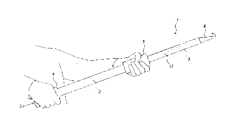
[0022] As can be seen in FIGs. 1 and 2, an embodiment of a big bag knife (1)
according to the present application comprises a back part (2) and a front
part (3) that
partially extends in the back part (2) in a retracted, compact or storage
position (see
FIG. 1A and FIG. 2A) as well as in an extended or use position (see FIG. 1B
and FIG.
2B). In an embodiment, in the retracted position of the big bag knife (1) as
shown in
FIG. 1A, the back part (2) extends completely around the front part (3). As
can be seen
CA 03076308 2020-03-18
WO 2019/141703 PCT/EP2019/050995
7
in FIG. 1B, the front part (3) is arranged with a blade (6) at the front
thereof. As can be
seen in FIG. 1A, this blade (6) is sheathed by the back part (2) in the
retracted position
of the big bag knife (1). As can be seen in FIG. 1B, the front part (3) is
arranged with a
longitudinal slot like opening (12) which forms part of a sliding mechanism
enabling
the front part (3) to slide in view of the back part (2), and more in
particular in and out
of the back part (2) between the retracted (or the compact position) and the
extended
position (or the use position) of the big bag knife (1). As further can be
seen in FIGs. 1
and 2, the back part (2) is provided with a back handgrip (4) and the front
part (3) is
provided with a front handgrip (5). The term "handgrip" as used herein refers
to a
handle, particularly a hand sized handle designed to be held or grasped by a
hand,
particularly to be held or grasped by the palm of a hand, in order to use or
manipulate
the object comprising the handgrip. During the sliding movement of the front
part (3)
out of the back part (2), the front handgrip (5) moves away from the back
handgrip (4),
while during the sliding movement of the front part (3) into the back part,
the front
handgrip (5) moves towards the back handgrip (4). Each of the handgrips (4, 5)
are
arranged to be gripped by one of the hands of a user of the big bag knife (1),
as shown
in FIGs. 2A and 2B, for the retracted and extended position of the big bag
knife (1),
respectively. The sliding movement of the front part (3) versus the back part
(2) is then
operable by the hands of the user. The back part (2) and the front part (3)
are attached
to each other in a slideable way. In the retracted position, the blade (6) is
sheathed by
the back part (2) and the blade (6) is inaccessible to the user, while in the
extended or
use position, the blade (6) is freed from the back part (2), or in other words
situated
outside the back part (2) and can be used to pierce into and cut a big bag.
The blade (6)
thus moves out of the back part (2) by sliding the front part (3) in view of
and out of
the back part (2). In an embodiment, as can be seen in FIGs. 3, 5, 7, 10, 15
and 17, the
front handgrip (5) is mounted on the front part (3) in such a way that in the
retracted
position, the front handgrip (5) abuts against the back handgrip (4).
[0023] As can be seen in FIGs. 3 and 4, the back part (2) has an outer
circumferential
wall (2a) extending along a longitudinal direction (X) and having a certain
first length
(Li). In an embodiment, the outer circumferential wall (2a) has an elongated
cylindrical shape and more in particular a cylindrical shape with an oval
base. The
back part (2) further has a back end (21) and a front end (22). The outer
CA 03076308 2020-03-18
WO 2019/141703 PCT/EP2019/050995
8
circumferential wall (2a) surrounds an inner space (2b). In an embodiment, as
can be
seen in FIGs 1 and 2, this inner space (2b) is open at the back end (21)
thereof in order
to allow fertilizer that is in the inner space (2b) to get out of this inner
space (2b). The
inner space (2b) further comprises a top side (23) and a bottom side (24).
[0024] Furthermore, a front part (3) is provided that is arranged at least
partially inside
the back part (2) in the retracted as well as in the extended position of the
big bag
knife (1), and more in particular that is arranged completely inside the back
part (2) in
the retracted position thereof. The front part (3) has an outer
circumferential wall (3a)
extending along the longitudinal direction (X) and having a certain second
length (L2).
In an embodiment, also the front part (3) has an elongated cylindrical shape
and more
in particular with an oval base. The front part (3) has a back end (31) and a
front end
(32). The outer circumferential wall (3a) surrounds an inner space (3b). The
inner
space (3b) comprises a top side (33) and a bottom side (34).
[0025] In an embodiment, as is viewable in FIGs. 3, 7 and 15, the first length
(Li)
equals the second length (L2) including the part of the blade (6) that extends
out of the
front part (3).
[0026] The blade (6) that is used to pierce and to cut open a big bag is more
in
particular mounted at the back end (31) of the front part (3). As can be seen
on FIGs 1,
3, 4, 7, 9, 14, 15 and 16, the blade (6) more in particular has a hook shape
with a sharp
end, more in particular a gut hook shape with a sharp end.
[0027] In an embodiment, as can be seen in FIG. 8, the blade (6) may be flat
(or in
other words have a narrow width) and in that way is leaving part of the front
end (31)
of the front part (3) open. As a result, the content of the big bag such as
fertilizer could
enter the inner space (3b) via this open front end (31), which is not desired.
Therefore,
a plug (30), for instance in aluminum, could be provided to close off the
front end (31)
of the inner space (3b) of the front part (3) to avoid the content of the big
bag to enter
the inner space (3b) of the front part (3).
[0028] The back handgrip (4) is more in particular mounted at the height of
the back
end (21) of the back part (2), while the front handgrip (5) is mounted in the
vicinity of
the back end (31) of the front part (3).
[0029] In an embodiment of a big bag knife (1) according to the application,
both the
back and the front handgrip (4, 5) have an outer circumferential wall (4a,
5a), in
CA 03076308 2020-03-18
WO 2019/141703 PCT/EP2019/050995
9
particular having an elongated cylindrical shape, and more in particular a
cylindrical
shape with an oval base, extending along a longitudinal direction (X) over
part of the
first length (Li) of the back part (2), respectively the second length (L2) of
the front
part (3). In an embodiment, the back handgrip (4) as well as the front
handgrip (5)
have an inner side that defines a shape corresponding the shape of the outer
circumferential wall (2a) of the back part (2). More in particular, the inner
side of both
handgrips (4, 5) are arranged with transverse extending ribs (5b) that define
an
elongated cylinder, more in particular a cylinder with an oval base. In an
embodiment,
the back and front handgrip (4, 5) are formed out of two parts, more in
particular two
similar parts, that can be connected to each other, for instance by a clicking
or
screwing mechanism.
[0030] In order to prevent that a hand holding the back handgrip (4) would
slip off of
the back handgrip (4), for instance when sliding the front part (3) out of the
back part
(2) and when pulling the big back cutting knife (1) towards the user during
the cutting
operation of the big bag, the outer circumferential wall (4b) may be provided
with an
end part (4c) having a larger diameter then the diameter of the outer
circumferential
wall (4b). Likewise, the front handgrip (5) may be provided with an end part
(Sc)
having a larger diameter then the diameter of the outer circumferential wall
(5b) to
prevent that the other hand of the user could easily slip off of the front
handgrip (5)
when for instance the user pulls at the front handgrip (5) to move the front
part (3) out
of the back part (2).
[0031] As can be seen in FIGs. 1B, 2B, 8 and 14, the sliding mechanism
comprises
further to the longitudinal slot like opening (12) a sliding element (11)
which is
movable back and forth into this longitudinal slot like opening (12).
[0032] In a possible embodiment, as shown in FIG. 8, the longitudinal slot
like
opening (12) extends over at least part of the first length (L1) of the back
part (2).
More in particular, this longitudinal slot like opening (12) starts inside the
front
handgrip (5) when the big bag knife (1) is in its retracted position at the
height of the
end (11a) of the sliding element (11) situated closest to the back end (21) of
the back
part (2), and ends inside the front handgrip (5) when the big bag knife (1) is
in its
extended or use position at the height of the end (1 lb) of the sliding
element (11)
situated closest to the front end (22) of the back part (2). The longitudinal
slot like
CA 03076308 2020-03-18
WO 2019/141703 PCT/EP2019/050995
opening (12) is thus bounded (closed off) at both longitudinal ends thereof
and the
sliding element (11) has such a form that it cannot move out of the
longitudinal slot
like opening (12) or in others words, the movement of the sliding element (11)
in
longitudinal slot like opening (12) is limited by both longitudinal ends (12a,
12b) of
5 the longitudinal slot like opening (12), having as a consequence that
also the
movement of the front part (3) in view of the back part (2) is limited. This
prevents
that the front part (3) could be released from the back part (2). More in
particular, the
longitudinal slot like opening (12) is provided in the bottom side (24) of the
back part
(2).
10 [0033] The sliding element (11) has such a form that it is not able to
leave the
longitudinal slot like opening (12) when the big bag knife (1) is assembled.
More in
particular, the sliding element (11) is arranged on or connected to the front
part (3).
Furthermore, in an embodiment, the sliding element (11) fits in a hole (5c)
(see FIGs.
5, 10 and 17) provided in the inside of the front handgrip (5). In an
embodiment, the
sliding element (11) can be in the form of a strong bent metal wire or an
aluminum or
plastic beam or cube.
[0034] In an embodiment, as can be seen in FIGs. 1A and 14, a longitudinal
groove
(10) can be provided that extends along at least part of the second length
(L2) of the
front part (3). More in particular, the longitudinal groove (10) has an open
top end, a
closed bottom end and closed longitudinal side ends. More in particular, the
groove
(10) extends over the full second length (L2) of the front part (3). This
groove (10)
ensures the strength of the profile of the front part (3).
[0035] To prevent that the front part (3) could move unintentionally in view
of the
back part (2), a locking mechanism can be provided that takes care that the
movement
of the front part (3) in view of the back part (2) is locked in the retracted
position,
and/or in the extended position.
[0036] In a first possible embodiment of a locking mechanism according to the
present
application, as shown in FIGs. 3 to 6, the locking mechanism comprises a
resilient
element (7) that is arranged inside the space (3b) of the front part (3). This
resilient
element (7) is at one end provided with a bulge (7a). The other end of the
resilient
element (7) is designed as an attachment end (7b) to attach the resilient
element (7) to
the front part (3), more in particular to the bottom side (3b) of the front
part (3). The
CA 03076308 2020-03-18
WO 2019/141703 PCT/EP2019/050995
11
resilient element (7) can be in the form of a bendable leafspring that is more
in
particular made out of rustfree spring steel.
[0037] The locking mechanism furthermore comprises
- a
first hole (8) that is arranged to fit the bulge (7a) in it in a releasable
way,
meaning that the bulge (7a) can be moved in and out of this first hole (8),
that is
situated in the vicinity of the back end (21) of the back part (2), more in
particular before the back handgrip (4), and is provided to lock the movement
of
the front part (3) in view of the back part (2) in a direction towards the
extended
position when the big bag knife (1) is in the retracted position, and
- a second hole (9) that is arranged to fit the bulge (7a) in it in a
releasable way,
that is situated in the vicinity of the front end (22) of the back part (2)
and that is
provided to block the movement of the front part (3) in view of the back part
(2)
in a direction towards the retracted position when the big bag knife (1) is in
the
extended position. In the extended position, the hole is surrounded by the
inner
circumferential wall (5a) from the front handgrip (5).
[0038] It is remarked that the resilient element (7) can also be attached to
the top side
(33) of the front part (3). In case the resilient element (7) is attached with
its
attachment end (7b) to the bottom side (34) of the front part (3), then the
first and
second hole (8, 9) are arranged in the top side (23) of the back part (2),
while when the
resilient element (7) is attached with its attachment end (7b) to the top side
(33) of the
front part (3), then the first and second hole (8, 9) are arranged in the
bottom side (24)
of the back part (2).
[0039] In the locking position of the locking mechanism as shown in FIGs. 3 to
6, or
in other words in the retracted position of the big bag knife (1), the bulge
(7a) of the
resilient element (7) is situated in the first hole (8) provided in the back
part (3) near
the back handgrip (4). In order to enable the front part (3) to move in view
of the back
part (2), the bulge (7a) of the resilient element (7) needs to be released out
of this first
hole (8). This is done by pushing the front handgrip (5) in view of the back
handgrip
(4) with a sufficient force enabling the bulge (7a) to move out of the first
hole (8). The
front part (3) is then slid in view of the back part (2) until it reaches its
maximum
extended position, through which also the big bag knife (1) will be in its
extended
position. In this extended position, the bulge (7a) will move into the second
hole (9).
CA 03076308 2020-03-18
WO 2019/141703 PCT/EP2019/050995
12
To close the big bag knife (1) again, or in other words to bring the big bag
knife (1)
back from its extended to its retracted position, the front handgrip (5) needs
to be
pulled towards the back handgrip (4) through which the bulge (7a) will move
out of
the second hole (9) and the front part (3) will move towards the back part (2)
until the
fully retracted position is reached, in which case the bulge (7a) will move in
the first
hole (8). This first embodiment ensures that there is a locking position as
well in the
retracted as in the extended position of the big bag knife (1).
[0040] As can be seen in FIGs. 13 to 18, a push button (16) can be arranged on
the
front handgrip (5) that can be used to push the bulge (7a) downwards out of
the first
hole (8) in its retracted position and out of the second hole (9) in its
extended position.
In that case, a hole (17) (see FIG. 4) is provided into the front handgrip (5)
in which
the push button (16) is inserted.
[0041] In a second embodiment of a locking mechanism according to the present
application, as shown in FIGs. 7 to 12, a resilient element (13) is provided
that is
attached to the front part (3) of the big bag knife (1). More in particular,
the resilient
element (13) is mounted on the back end (31) of the front part (3). In an
embodiment,
the resilient element (13) is arranged with a bulge (13a) that is able to hook
below a
pin (14). This pin (14) is more in particular attached to the back part (2) of
the big bag
knife (1). More in particular, the pin (14) is attached to the back handgrip
(4) that is
mounted on the back part (2). The pin (14) is more in particular located in
the vicinity
of the back end (21) of the back part (2). The resilient element (13) can be
in the form
of a bendable leafspring that is more in particular made out of rustfree
spring steel.
[0042] In the locking position of this second embodiment of a locking
mechanism as
shown in FIGs. 7 to 12, or in other words in the retracted position of the big
bag knife
(1), the bulge (13a) is hooked below the pin (14). In order to enable the
front part (3)
to move in view of the back part (2) to bring the big bag knife (1) to its
extended
position, the front handgrip (5) is pushed away from the back handgrip (4)
enabling
the bulge (13a) to slide under the pin (14) such that the bulge (13a) is
released from
the pin (14). When the big bag knife (1) is then brought back from its
extended to its
retracted position, or by pulling the front handgrip (5) towards the back
handgrip (4),
at the moment that the resilient element (13) comes into contact with the pin
(14), the
bulge (13a) of the resilient element (13) is pulled under the pin (14) and
consequently
CA 03076308 2020-03-18
WO 2019/141703 PCT/EP2019/050995
13
slides under the pin (14) and hook behind it, through which the big bag knife
(1) is
locked in its retracted position. This ensures that there is a locked position
in the
retracted position of the big bag knife (1).
[0043] It is remarked that the resilient element (13) could also be arranged
such that it
hooks over the pin (14) instead of beneath the pin (14). In that case, the
bulge (13a)
would be oriented upwards inside of downwards. In that case, all movements of
the
bulge (13a) would be opposite of the movements as described in the previous
paragraph.
[0044] Furthermore, as can be seen in FIGs. 7, 10, 11 and 12, a friction pad
(15) can
be provided between the front part (3) and the back part (2). This friction
pad more in
particular is a pin (15a) around which a spring (15b) is wound. This friction
pad (15)
extends more in particular in the inner space (3b) of the front part (3) and
is on the one
hand connected to the outer circumferential wall (3a) of the front part (3)
and on the
other hand connected to the outer circumferential wall (2a) of the back part
(2). This
friction pad (15) creates a resistance such that there needs to be a certain
force to move
the front part (3) in view of the back part (4).
[0045] In an embodiment, the big bag knife (1) according to the present
application
has an overall length of approximately 0.6 m in the retracted position thereof
and a
length of approximately 1.0 m in the extended position thereof.
[0046] When a user wants to use the big bag knife (1) to cut a big bag (not
shown on
the FIGs), the user places himself / herself at a distance of approximately
one meter
from the big bag. Then the user takes the back handgrip (4) in one hand and
the front
handgrip (5) in the other hand. Thereafter, the user pushes on the front
handgrip (5) to
slide the front part (3) out of the back part (2) until the big bag knife (1)
reaches its full
length and is accordingly in the extend or use position. To be able to pierce
and to cut
the underside of a big bag, the tip of the hook shape of the blade (6) needs
to be
oriented upwards. The user can then pierce the big bag in the underside
thereof pull
the big bag knife towards himself / herself making an incision in the
underside of the
big bag, enabling emptying of the content of the big bag. Since the user is at
a distance
of about 1 meter from the cutting blade (6), the user will be in a safe
position not to
come into contact with the contents of the big bag and not to hurt him/herself
by
means of the cutting blade. After use, the user needs to pull at the front
handgrip (5)
CA 03076308 2020-03-18
WO 2019/141703 PCT/EP2019/050995
14
such that the bulge (7a) of the resilient element (7) leaves the second hole
(8), then
pull the front handgrip (5) towards the back handgrip (4), in that way sliding
the front
part (3) in the back part (2) until the retracted position is reached, in
which position the
bulge (7a) of the resilient element (7) enters the first hole (8) again. The
big bag knife
(1) can then be taken along by the user and stored in a safe way.