Note: Descriptions are shown in the official language in which they were submitted.
1
BUS WITH COOLED IN-WHEEL ELECTRIC ENGINES
Technical field
The invention lies in the field of engine cooling. More precisely, the
invention proposes a bus with
driving wheels which comprises cooled electric engines.
Background of the invention
Electric buses are provided with electric engines. During propulsion phases
and regenerative
phases, the electric machines heat. This temperature elevation reduces the
efficiency since the
permanent magnet properties decrease. In addition, a high temperature may
irremediably damage
the permanent magnets and other electric devices.
In order to preserve the yield, an electric engine is generally provided with
a cooling device. A
cooling flow prevents excessive heat peaks, and allows a temperature control.
Yet, this temperature
control may turn out cumbersome when the corresponding vehicle runs in cities
where speed is
limited by law or by traffic jam. Then, the potential cooling flow is limited.
Uphill slopes require
more electric power which heat even more the electric engines.
Moreover, the positioning of the heat exchanger must comply with several
requirements, notably in
mass transportation vehicles such as buses. Indeed, the available place is
reduced. In addition, the
cost, the weight and the passenger comfort must be considered as well. On top
of this, servicing
and collisions with other vehicles also affect the way the heat exchangers are
arranged close to
seating and standing passengers.
The document DE 197 32 637 Al discloses an omnibus comprising an in-wheel
electric engine
with a cooling pipe where cooling water flows.
The document JP 2009 227130 A discloses a wheel with an in-wheel engine
lubricated by an oil
circuit. The oil flows through an oil cooler in the middle of the oil path.
The document US 2019/068028 Al discloses a four-wheel vehicle equipped with a
cooling
mechanism. Each wheel is dotted with an electric engine cooled by an oil
cooler. The oil coolers
compose heat exchangers coupled to the radiator.
Technical problem to be solved
It is an objective of the invention to present a bus, which overcomes at least
some of the
disadvantages of the prior art.
Summary of the invention
According to a first aspect of the invention, it is provided a bus, notably an
articulated bus with
several units, the bus comprising: a passenger compartment adapted for at
least fifty passengers, a
wheel housing, a wheel disposed in the wheel housing and comprising an in-
wheel electric engine,
CA 3076443 2020-03-20
2
a cooling circuit in fluid flow communication with the in-wheel electric
engine and comprising a
heat exchanger outside the wheel housing.
Preferably, the cooling circuit comprises a first passage which is outside the
in-wheel electric
engine and which comprise a first inner width Wl, the cooling circuit further
comprising a second
passage which is in the in-wheel electric engine and which comprise a second
inner width W2, the
first inner width W I representing at least 80% of the second inner width W2,
optionally the first
inner width W 1 is larger than the second inner width W2.
Preferably, the heat exchanger is transversally and/or vertically level with
the wheel, respectively
with the in-wheel electric engine, the bus further comprising a seat row above
said heat exchanger,
or a seat above the heat exchanger.
Preferably, the wheel housing comprises a tight wall and/or a protection bar
between the wheel and
the heat exchanger.
Preferably, the bus comprises an enclosure in which the heat exchanger is
arranged, said enclosure
being adjacent to the wheel housing and/or the passenger compartment, the bus
is notably adapted
such that the heat exchanger heats the passenger compartment.
Preferably, the wheel is a first wheel, the bus further comprising a second
wheel identical to the
first wheel and disposed in the wheel housing longitudinally at distance from
the first wheel, the
cooling medium being adapted for flowing through the in-wheel electric engine
of said second
wheel.
Preferably, the cooling circuit comprises a pump adapted for pressurizing a
cooling liquid in the
first wheel and in the second wheel, and/or a tank with a cooling liquid, such
as a water glycol mix,
the cooling liquid being intended to flow through the in-wheel electric engine
in order to cool it.
Preferably, the bus comprises a suspension arm adapted to pivot with respect
to the wheel housing
and/or the passenger compartment, the cooling circuit comprising a tube,
notably a resilient tube,
joined to said suspension arm and being in fluid flow communication with the
in-wheel electric
engine.
Preferably, the suspension arm is an upper suspension arm, the cooling circuit
comprising a pipe
fixed to said upper suspension arm, said pipe being stiffer than the resilient
tube.
Preferably, the bus comprises a battery pack adapted for electrically powering
the in-wheel electric
engine, the cooling circuit comprising a cooling unit adapted for cooling said
battery pack, the
wheel housing being disposed longitudinally between the battery pack and the
heat exchanger.
Preferably, the in-wheel electric engine comprises a rotor and a stator, said
stator comprising a
diameter and a thickness TH along the rotation axis of the in-wheel electric
engine.
Preferably, the stator is arranged in the rotor, the cooling circuit
comprising an inner network
through the stator in order to cool said stator.
Preferably, the wheel further comprises a disc brake with a brake disc, the
distance D between the
brake disc and the stator being larger than the width W of the stator.
CA 3076443 2020-03-20
3
Preferably, the bus comprises a frame and a movable wheel support on which the
wheel is rotatably
fixed, the wheel support is notably disposed between the brake disc and the in-
wheel electric
engine.
Preferably, transversally, the in-wheel electric engine comprises an inner
face and an outer face, the
cooling circuit comprising an inlet and an outlet on the inner face, the inlet
and the outlet notably
being arranged on the inner face, preferably in the upper half of the inner
face.
Preferably, the wheel comprises a radial space between the in-wheel electric
engine and the rim of
the wheel, said radial space being radially larger than the outer radius of
the in-wheel electric
engine, possibly at least two times larger than the outer radius.
Preferably, the cooling circuit is a first cooling circuit, the wheel housing
is a first wheel housing,
the bus further comprising additional wheel housings and additional cooling
circuits which are
identical to the first cooling circuit and which are each associated with one
of the additional wheel
housings, the additional cooling circuits notably being independent from one
another.
Preferably, the cooling circuit comprises a first passage which is outside the
in-wheel electric
engine and which comprise a first inner width Wl, the cooling circuit further
comprising a second
passage which is in the in-wheel electric engine and which comprise a second
inner width W2, the
first inner width W I being larger than the second inner width W2.
Preferably, the second inner width W2 represents at least 4% of the outer
diameter of the in-wheel
electric engine.
Preferably, the heat exchanger is longitudinally aligned with the wheel.
Preferably, the heat exchanger is vertically level with the passenger
compartment.
Preferably, the heat exchanger comprises a heat dissipation device.
Preferably, the wheel extends over the whole height of the heat exchanger.
Preferably, the pump and/or the tank are arranged in the enclosure.
Preferably, the heat exchanger is intended to be cooled by the bus
environment.
Preferably, the heat exchanger is adapted for cooling a cooling medium flowing
through the
cooling circuit.
Preferably, the wheel comprises a rim with an inner space, the in-wheel
electric engine being at
least partially disposed in said inner space.
Preferably, the inner space comprises a first outer diameter which is larger
than a second outer
diameter of the in-wheel electric engine, preferably at least two times
larger.
Preferably, the additional cooling circuits are separate and distinct.
Preferably, the wheel comprises an outer half and an inner half in which the
in-wheel electric
engine is arranged, the in-wheel electric engine being at distance from said
outer half.
Preferably, the wheel support is a steering knuckle which is adapted for
moving vertically and/or
for pivoting about a vertical pivot axis.
CA 3076443 2020-03-20
4
Preferably, the cooling circuit comprises water, and is notably adapted to
keep the water
temperature under 100 C.
Preferably, the second wheel and the heat exchanger are aligned, and/or
transversally overlapping.
Preferably, the cooling fluid is isolated from the bus environment by the
cooling circuit.
Preferably, the cooling circuit comprise a first portion fixed to a suspension
arm, and a second
portion of reduced stiffness which comprise a lower stiffness than the first
portion.
Preferably, the second portion is between the first portion and the engine.
Preferably, the first portion is at distance from the engine.
It is another aspect of the invention to provide a bus, notably an articulated
bus with several units,
the bus comprising: a passenger compartment adapted for at least fifty
passengers, a seat row,
notably a longitudinal seat row; a wheel disposed under the seat row and
comprising an in-wheel
electric engine, a cooling circuit in fluid flow communication with the in-
wheel electric engine and
comprising a heat exchanger under the seat row.
The passenger compartment is not an essential aspect of the invention.
It is another aspect of the invention to provide a cooling process of an in-
wheel electric engine for a
bus, the bus comprising: a capacity of at least fifty passengers notably
defined by a passenger
compartment, a wheel housing, a wheel with an in-wheel electric engine, a
cooling circuit with a
cooling liquid, a heat exchanger at distance from the wheel, a connection
between the heat
exchanger and the in-wheel electric engine, the cooling process comprising the
steps: heating the
in-wheel electric engine, and cooling the in-wheel electric engine by means of
the cooling liquid,
wherein the speed of the cooling liquid in the connection is similar to the
speed of the cooling
liquid in the in-wheel electric engine, the bus notably being in accordance
the invention, and the
bus comprises a seat over the cooling circuit.
The cooling liquid may generally be a fluid such as a gas.
Preferably, the speed of the cooling liquid in the connection represents from
50% to 150%, or from
80% to 120%, of the speed of the cooling liquid in the in-wheel electric
engine.
Preferably, during step cooling the in-wheel electric engine, the passenger
compartment is heated,
and the pressure of the cooling fluid in the connection is similar to the
pressure of the cooling fluid
in the in-wheel electric engine.
Preferably, the heat exchanger is at distance and/or outside the wheel
housing.
Preferably, the wheel is inside the wheel housing.
It is another aspect of the invention to provide a cooling process of an in-
wheel electric engine for a
bus, the bus comprising: a passenger compartment adapted for receiving at
least fifty passengers, a
wheel housing, a wheel and comprising an in-wheel electric engine, a cooling
circuit with a cooling
CA 3076443 2020-03-20
5
liquid, a heat exchanger at distance from the wheel, a connection between the
heat exchanger and
the in-wheel electric engine, the cooling process comprising the steps:
heating the in-wheel electric
engine, and cooling the in-wheel electric engine by means of the cooling
liquid, wherein the flow
speed of the cooling liquid in the connection represents from 40% to 200%, or
from 50% to 150%,
or from 80% to 120%, of the flow speed of the cooling liquid in the in-wheel
electric engine, the
bus notably being in accordance with the invention.
The heat exchanger is not an essential feature of the invention. It is another
aspect of the invention
to provide a cooling process, notably a temperature management process, of an
in-wheel electric
engine for a bus, the bus comprising: a passenger compartment adapted for
receiving at least fifty
passengers, a wheel housing, a wheel and comprising an in-wheel electric
engine, a cooling circuit
with a cooling liquid, the cooling process comprising the steps: heating the
in-wheel electric
engine, and cooling the in-wheel electric engine by means of the cooling
liquid which is cooled
outside the wheel and notably outside the wheel housing, the bus notably being
in accordance with
the invention.
The cooling liquid flow speed(s) may be an average flow speed, or a maximum
flow speed.
It is another aspect of the invention to provide a use of a heat exchanger for
heating the passenger
compartment of a bus, wherein the bus comprises:
a wheel housing,
a wheel disposed in the wheel housing and comprising an in-wheel electric
engine,
a cooling circuit for with the in-wheel electric engine and comprising a heat
exchanger;
an enclosure in heat exchange with the passenger compartment and in which the
heat exchanger is disposed, the bus notably being in accordance with the
invention.
It is another aspect of the invention to provide a use of a heat exchanger for
heating a passenger
compartment of a bus, wherein the bus comprises a wheel housing, a wheel in
said wheel housing,
an electric in-wheel engine in said wheel, a cooling circuit through the
electric in-wheel engine, the
heat exchanger being part of said cooling circuit, the bus notably being in
accordance with the
invention.
It is another aspect of the invention to provide a use of a heat exchanger for
heating the passenger
compartment of a bus, wherein the bus comprises:
a wheel housing,
a wheel disposed in the wheel housing and comprising an in-wheel electric
engine,
a cooling circuit thermally cooperating with the in-wheel electric engine and
comprising a heat exchanger; and optionally
CA 3076443 2020-03-20
6
an enclosure in thermal communication with the passenger compartment and in
which the heat exchanger is disposed, the bus notably being in accordance with
the
invention.
It is another aspect of the invention to provide a use of a heat exchanger for
heating seat of a bus,
wherein the bus comprises:
a wheel housing,
a wheel disposed in the wheel housing and comprising an in-wheel electric
engine,
a cooling circuit thermally cooperating with the in-wheel electric engine and
comprising a heat exchanger thermally coupled to the seat;
the bus notably being in accordance with the invention.
Preferably, the bus further comprises an enclosure in which the heat exchanger
is disposed and the
set being above said enclosure.
Preferably the seat comprises a seat place row thermally coupled to the heat
exchanger and/or
above said enclosure.
The different aspects of the invention may be combined to each other. In
addition, the preferable
features of each aspect of the invention may be combined with the other
aspects of the invention,
unless the contrary is explicitly mentioned.
Technical advantages of the invention
The invention improves the flow control through the cooling circuit. It
provides a position for the
heat exchanger which is sufficiently remote from the hot source for a better
cooling, but
sufficiently close in order to shorten the lines so as to lower the pressure
losses.
In addition, the pressure losses are further managed by specific diameter or
width choices. These
dimensions foster smooth flow in spite of the connection deformation, and of
the vibrations
generated by the contact between the wheel and the ground unevenness.
The invention addresses the technical problem of cooling a substantially small
size in-wheel
electric engine equipping a steering and driving wheel, where said wheel
drives a bus which keeps
a spacious passenger compartment with seat rows. Thus, the passenger capacity
is preserved, and
the ratio between seat places and standing places is optimized.
Brief description of the drawings
Several embodiments of the present invention are illustrated by way of
figures, which do not limit
the scope of the invention, wherein:
- figure 1 provides a schematic illustration of a side view of a bus in
accordance with a
preferred embodiment of the invention;
CA 3076443 2020-03-20
7
- figure 2 provides a schematic illustration of an aerial view of a
portion of a bus frame in
accordance with a preferred embodiment of the invention;
- figure 3 provides a schematic illustration of a longitudinal view
of a suspension assembly
in accordance with a preferred embodiment of the invention;
- figure 4 provides a schematic illustration of through cut of a wheel with
a cooling circuit in
accordance with a preferred embodiment of the invention;
- figure 5 provides a schematic illustration of a transversal view
of a wheel with a cooling
circuit in accordance with a preferred embodiment of the invention;
- figure 6 provides a schematic illustration of the interface
between a connection and an
engine of a cooling circuit in accordance with a preferred embodiment of the
invention;
- figure 7 provides a schematic illustration of a cooling process
in accordance with a
preferred embodiment of the invention.
Detailed description of the invention
This section describes the invention in further detail based on preferred
embodiments and
on the figures. Similar reference numbers will be used to describe similar or
the same concepts
throughout different embodiments of the invention.
It should be noted that features described for a specific embodiment described
herein may be
combined with the features of other embodiments unless the contrary is
explicitly mentioned.
Features commonly known in the art will not be explicitly mentioned for the
sake of focusing on
the features that are specific to the invention. For example, the bus in
accordance with the invention
is evidently controlled by a computer, even though such a computer is not
explicitly referenced on
the figures nor referenced in the description.
By way of convention, it may be defined that the word "longitudinal" refers to
the longitudinal
direction and may correspond to the main driving direction of the bus. It may
be along the main
central axis of the vehicle. The word "transversal" refers to the transversal
direction and may be
perpendicular to the longitudinal direction. It may be understood that the
directions are not used in
a strict meaning. Indeed, each direction used below may include a variation of
at most: 5 , or 2 , or
1 , with respect to a strict meaning. The skilled in the art will understood
that a longitudinal pivot
axis may be inclined with respect to the longitudinal direction of the bus
and/or the horizontal
direction.
In the following description and claims, the mentioned length(s), width(s),
and thickness(es) may
be average ones.
The radial direction is understood as perpendicularly to an associated wheel
rotation axis. The
radial direction is along the radius of a wheel.
The term "similar" used in relation with a value such as a size or flow, is
understood as implying a
variation of at most: 50%; preferably 20%, more preferably 10%.
CA 3076443 2020-03-20
8
It should be noticed that the present drawings generally provide
configurations where wheels are
substantially parallel to the longitudinal direction. The steering angle is of
0 . The vehicle may
drive along a straight trajectory. However, the skilled in the art will be
able to adapt the following
teaching to situations where the steering angle of the bus is changed.
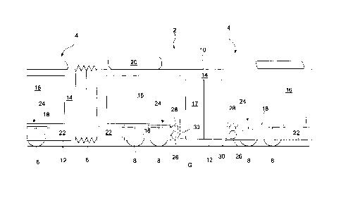
Figure 1 shows a vehicle for mass transportation in accordance with a
preferred embodiment of the
invention. The vehicle is partially represented.
The vehicle is adapted for transportation of passengers in cities and may
transport about fifty, or
one hundred passengers, for instance one hundred and twenty passengers. The
vehicle may be a bus
2, notably an electric bus 2. The bus 2 may include electric driving engines
and electric batteries
(not represented) powering the electric driving engines. The bus 2 may be
purely electric, in the
meaning that it is only driven by electric power. The bus 2 may be combustion
engine free.
The bus 2 may be an articulated bus. It may comprise a first unit 4 and a
second unit 4 (partially
represented). Each unit 4, may form a body, and/or may form a rigid cart. Each
unit 4 may be a
trailer and/or a tractor. The units 4 may be similar or identical. These units
4 may be joined by a
joint, for instance a hinged joint 6 enabling the units 4 to swivel with
respect to each other.
In the current embodiment, only two units 4 are represented, however it is
contemplated in the
current invention that the electric bus 2 includes three, four, or more units
4; which are articulated
with respect to one another by hinged joint (s) 6. Then, the passenger
capacity may be of more than
two hundred. Each unit 4 may be self-supporting. Thus, each unit 4 may move
without the hinged
joint 6.
A bus formed of a single unit is also considered in the invention.
Each unit 4 may include several wheels 8 engaging the ground G. Pairs of
symmetric wheels 8 may
form axles, for instance four axles for each unit 4. The axles and thus the
wheels 8 may be
distributed along the length of the bus 2. At least one pair of wheels is
formed of steered wheels.
Optionally, each wheel 8 of the bus 2 or of at least one unit 4 are steered
wheels and/or driving
wheels.
The bus 2 may include a bus structure. The bus structure may distribute and/or
support the weight
of the bus, and load therein. The bus structure may include a roof 10, and/or
a passenger platform
12, and/or side walls 14. The side walls 14 may be outer walls. Two
transversally opposite side
walls 14 may go down from the roof 10 to the passenger platform 12. They may
form the
bodywork of the bus 2. They may mask the wheels 8. The bodywork may be part of
the bus
structure. The side walls 14 may receive windows 16 and doors 17 for
passengers. Optionally,
doors 17 are arranged in one of the two side walls 14, notably between windows
16.
For instance; the side walls 14 may close the wheel housings 18. Optionally,
at least one or each
wheel housing 18 may receive two longitudinally spaced wheels 8. The wheel
housings 18 may
form downwardly open boxes. The wheel housings 18 may exhibit four faces in
front of the wheels
CA 3076443 2020-03-20
9
8. At least one or each wheel housing 18 may be adapted for blocking front,
rear and top
projections from the associated wheel. The wheel housings 18 may be
longitudinally at distance
from the ends of the units 4. The wheel housings 18 may be arranged below the
windows 16. The
door 17 may be disposed between two wheel housings 18 of the corresponding
unit 4.
Generally, the or each wheel housing 18 may be understood a space in which at
least one wheel is
arranged. The or each wheel housing 18 may be a wheel cavity. The or each
wheel housing 18 may
be a wheel guard.
Equipment may be provided on the roof 10. For instance, the bus may comprise
an air conditioning
device 20. The air conditioning device 20 may be adapted to cool air in the
passenger compartment
(behind the door 17). It may be adapted for keeping the temperature between 18
C and 25 C for the
passenger comfort. This air conditioning device 20 may be reversible and may
heat the passenger
compartment during winter. It may comprise a compressible gas.
The bus 2 may comprise at least one battery pack 22. The battery packs 22 may
power electric
engines driving the bus 2. The battery packs 22 may power electric engines
(not represented) which
activate the wheels 8. The electric engines may be in-wheel electric engines.
For instance, each
wheel housing 18 is associated with a battery pack 22. The battery packs 22
may be independent.
In the current example, each unit 4 may comprise four battery packs 22. By way
of illustration, the
bus 2 includes eight battery packs 22 and eight wheel housings 18. There may
be sixteen wheels 8,
for instance each with an electric engine. The battery packs 22 may power
other equipment of the
bus 2.
In order to cool the electric engines, notably the in-wheel electric engines,
the bus 2 may comprise
at least one cooling circuit 24. The bus 2 may comprise one cooling circuit 24
for each of the wheel
housings 18, and thus for each of the wheel pairs. Each battery pack 22 may be
associated with a
cooling circuit 24. Each cooling circuit 24 may be associated with one wheel
housing 18, and/or
with at least one wheel 8. Each cooling circuit 24 may cool one or two
electric engines. At least
one door 17 may be between two adjacent cooling circuit 24. The cooling
circuits 24 may be
independent from each other. They may be separate and distinct. They may be at
distance from
each other in order to reduce the length of required pipes when considering
the whole vehicle.
The current configuration reduces the thermal stress of the cooling circuits
24, and improves the
general reliability. The cost and the weight are considered as well. The or
each cooling circuit 24
may comprise a closed loop, and/or vanes which are easier to control.
The or each cooling circuit 24 may comprise a tank 26. Each tank 26 may be a
closed and tight
vessel. Each tank 26 may be adapted for containing a cooling fluid, notably a
cooling liquid. The
cooling liquid may comprise water and glycol. The tank 26 may be adapted for
resisting to the
cooling fluid pressure. The cooling circuit may be adapted for avoiding
contact between the
cooling fluid and the bus environment.
CA 3076443 2020-03-20
10
The or each cooling circuit 24 may comprise a pump 28. The pumps 28 may be
adapted for sucking
up the cooling fluid, and for injecting it through the corresponding circuit
24. The pumps 28 may
inject the cooling fluid in the hydraulically connected electric engines in
order to cool them. The
cooling fluid pressure in the electric engines may be comprised between 0.5
bar and 2 bars.
The or each cooling circuit 24 may comprise a heat exchanger 30. The heat
exchanger(s) 30 may be
heat dissipator(s). Each heat exchanger 30 may be adapted to cool down the
cooling fluid flowing
therethrough by means of the pump 28. The heat exchangers 30 may be in thermal
contact of the
bus environment. The or each heat exchanger 30 may be separate and distinct
from the air
conditioning device 20. The heat exchangers 30 may be adapted to cool the
battery packs 22, the
tanks 26 and the electric engines.
The heat exchangers 30 may be vertically level with the passenger compartment.
The heat
exchangers 30 may be above the platform 12. They may heat the passenger
compartment.
At least one or each heat exchanger 30 may be at distance from the wheels 8.
They may be outside
the wheel housings 18. Thus, the heat exchangers 30 may be physically
protected from projections
propelled by the wheels 8.
At least one or each heat exchanger 30 may be arranged in an enclosure. The
enclosure may receive
the connected pump 28 and the connected tank 26. At least one or each
enclosure may be adjacent
to the corresponding wheel housing 18. The enclosure and the associated wheel
housing 18 may be
in contact of each other. Thus, the length of pipe is reduced such that the
pressure loss, the cost and
the weight are optimized. The cooling circuits 24 are more reliable. The
length of the pipes
becomes important when their diameter increases.
Figure 2 provides an aerial illustration of the frame 32 of a bus 2, notably
from a unit 4, in
accordance with a preferred embodiment of the invention. The longitudinal
central axis L and the
transversal direction T are represented. The longitudinal central axis L may
correspond to the
longitudinal direction L, and may be horizontal.
The bus 2 and/or the unit 4 may correspond to those as described in relation
with figure 1. Two
pairs or wheels 8 are disposed in the respective wheel housings 18. The
rotations axes 9 of the
wheels 8 are represented. The wheel rotations axes 9 may correspond to the
axles when the wheels
8 are aligned at each side. It may be understood that the wheels 8 comprise
toe-in or toe-out. Thus,
the term "aligned" may be understood in the meaning of the environment of the
invention.
In each wheel housing 18, the wheels 8 may form pairs. The wheel gap 8G
between the wheels 8 in
the same wheel housing may be smaller than the transversal width 8W of at
least one wheel 8 or of
each wheel 8. The wheels 8 of each pair are adapted to run on the same wheel
path. These wheels 8
may be transversally aligned. In each pair, the wheels 8 are longitudinally
offset. The wheel gap 8G
may separate them longitudinally. The wheels 8 of each pair may be identical.
CA 3076443 2020-03-20
11
The frame 32 may comprise longitudinal beams 34 and transversal beams 36. The
platform 12 may
be part of the frame 32. The longitudinal beams 34 may delimit transversally
the wheel housings
18. Transversal bars 38 may delimit longitudinally the wheel housings 18.
Other beams 40 may
also form the frame 32 and may delimit the wheel housing 18 and the frame 32.
The transversal bar
38 may be considered as a protection bar 38 between the wheels 8 and the heat
exchanger 30.
At least one or each wheel 8 may be a driving wheel. At least one or each
wheel 8, respectively
driving wheel, may comprise an electric engine 42. The electric engines 42 may
generally be
electric machines. The electric engines 42 may be in-wheel electric engines,
or more generally in-
wheel engines. The electric engines 42, notably the in-wheel electric engines
42,
may be powered by the battery pack 22. The cooling circuit 24 may comprising a
cooling unit 22C
in at least one of the battery packs 22. Each cooling unit 22C may be adapted
for cooling the
corresponding battery pack 22. The cooling units 22C may be in thermal contact
of the
corresponding battery pack 22, notably of the contained battery cells.
In the current example two battery packs 22 are represented, namely a left
battery pack 22 and a
right battery pack 22. The combination of the battery packs 22 and of the
electric engines 42,
notably the in-wheel electric engines 42, allows to drive the bus 2. These
electric components may
be adapted for driving the bus 2 at least at: 50 km/h or 100 km/h. These
speeds may be reached
with one hundred passengers in the passenger compartment 2P of the bus.
At least one or each wheel 2 may be joined to the frame 32 by a suspension
system 44. At least one
or each wheel is joined to the frame 32 by a dedicated suspension system 44.
The suspension
systems 44 may be separate and distinct from each other. At least one or each
suspension system 44
may comprise a steering module (not represented).
At least one or each suspension system 44 may comprise suspension arms 46. The
suspension arms
may be designated as pivoting arms. The suspension arms 46 may be pivotably
fixed to the frame
32, for instance to longitudinal beams 40. The suspension arms 46 may be
pivoting links, notably
swinging arms. The suspension arms 46 may pivot about horizontal pivot axis.
At least one or each
suspension arm 46 may pivot about longitudinal pivot axis 48. The longitudinal
pivot axes 48 may
be parallel.
The wheel housings 18 may comprise plates 50. The plates 52 may be vertical.
They may be tight.
They may be fixed to the transversal bars 38. The plates 50 may close tightly
the wheel housings
18. They may form longitudinal end walls thereon.
The frame 32 may exhibit enclosures 52. The plates 50 may be at the interface
between the wheel
housings 18 and the enclosures 52. The enclosures 52 may be adjacent to the
wheel housings 18. At
least one or each enclosure 52 may be adjacent to the passenger compartment
2P. The enclosures
52 may be above the platform 12. The position of the enclosures 52 with
respect to the wheel
housings 18 allows thermal cooperation. The enclosures 52, more precisely the
heat exchangers
CA 3076443 2020-03-20
12
disposed therein, are cooled by the wheel housings 18 which raises when the
bus drives due to the
air flow forced by the wheels.
The current portion of the bus 2, respectively of the unit 4, exhibit two
cooling circuits 24, namely
a left cooling circuit 24 and a right cooling circuit 24. The left and the
right cooling circuits 24 may
be separated by the passenger compartment 2P. They may be transversally
distant. They may be
hydraulically and/or thermally independent.
At least one cooling circuit 24 may comprise a tank 26 in the corresponding
enclosure 52, and/or a
pump 28 in the corresponding enclosure 52. At least one or each cooling
circuit 24 may comprise a
heat exchanger 30 in the enclosure 52. As an option, the enclosure 52 may
allow an air flow with
the passenger compartment 2P and/or with the bus environment. Thus, at least
one or each heat
exchanger 30 may provide calories to the bus environment and/or the passenger
compartment 2P.
Thus, the passenger compartment 2P may benefit from the calories generated by
the electric
engines 42. A kind of synergy is achieved.
As apparent from the current figure, each wheel housings 18 separates the
associated battery pack
22 and the associated enclosure 52. It may increase heat exchange while
allowing a height and a
transversal width reduction of the enclosures 52.
The integration of the cooling circuits 24 is performed in a narrow area.
Indeed, the cooling circuits
24 may be below seats 56. The seats 56 may form longitudinal rows. The seats
56 may be above
the cooling circuits 24. For instance, the tanks 26, the pumps 28 and the heat
exchangers 30 may be
under the seats 56.
Thus, the cooling circuits 24 may be disposed between the seats 56 and the
platform 12. Then the
cooling system 54 and its cooling circuits 24 only require a reduced place in
the bus since it is
divided in smaller units which are individually easier to arrange in the bus
2. At least one or the
cooling circuits 24 are adapted for heating the seat(s) 56. Then, the thermal
management of the
vehicle is improved. The thermal comfort of the seat(s) increases.
The cooling circuits 24 may comprise connections 58, or lines. The connections
58 may form
loops, notably closed loops. The pumps 28 may force the cooling liquid
circulation in the
associated loops. The cooling liquid may flow through the connections 58 in
order to meet the
battery packs 22, the engines 42, the heat exchangers 30; and thereby
achieving temperature
control. In addition, the connections 58 and the engines 42 may be configured
such that the flow
speeds in the connections 58 and the engines 42 are similar, and notably
reduced. The differences
of speeds may be of at most: 30%, or 20% or 10%. The considered speed may be
average speeds.
Accordingly, the cooling fluid speed remains homogeneous. Accelerations and
slowdowns are
controlled, notably at the interfaces of the engines 42. The pressures losses
are limited. In addition,
the liquid speed in the connections 58 may be limited in order to limit the
pressure losses therein.
CA 3076443 2020-03-20
13
Figure 3 provides a schematic illustration of a longitudinal view of a cooling
system 24, and of a
suspension system 44 in a wheel housing 18. The transversal direction T, the
longitudinal direction
L and the vertical direction V are provided. These directions (T, L, V) may be
perpendicular to
each other.
The bus 2 may correspond to those as described in relation with any one of
figures 1 and 2.
The suspension system 44 may be provided with a gas actuator 60 and a damper
62. In addition or
as an alternative, the gas actuator 60 forms a gas spring. Varying the gas
pressure therein may
allow to set its stiffness. This may be useful when the number of passengers
varies in the passenger
compartment 2P. The damper 62, also designated as shock absorber, may be
adapted to absorb and
dissipate energy when the wheel 8 meets a protrusion or a recess on/in the
ground G, namely the
road on which the bus 2 drives.
The suspension system 44 may comprise arms 46 or links. The suspension system
44 may comprise
pivoting arms 46 also designated as pivoting links. The pivoting arms 46 may
comprise an upper
pivoting arm 64 and a lower pivoting arm 66. The upper pivoting arm 64 and the
lower pivoting
arm 66 may pivot about longitudinal pivot axes 48. Pivot joints 48J may allow
the pivoting motions
of the pivoting arms (64; 66) about the longitudinal pivot axes 48. These
pivoting motions allow
the wheel 8 to move between an upper position and a lower position.
The gas actuator 60 may be joined to the upper pivoting arm 64 whereas the
damper 62 may be
joined to the lower pivoting arm 66. The damper 62 and the gas actuator 60 may
be separate and
distinct. They may be at distance from each other.
The lower pivoting arm 66 may be joined to the longitudinal beam 34 by means
of the lower pivot
joint 48J. A transversal beam 36 is apparent. The rotation axis 9 of the wheel
8 may extend through
the longitudinal beam 34. The ground clearance GC between the platform 12 and
the ground G is
represented. An upper longitudinal beam 40 of the frame 32 may form an upper
and outer end of
the wheel housing 18.
A wheel support 68 receives the wheel 8. The wheel support 68 may comprise
bearing about which
the wheel 8 turns around its rotation axis 8. The wheel support 68 may be
joined to the upper
pivoting arm 64 and the lower pivoting arm 66. Thus, the outboard ends of
these pivoting arms
may be maintained at a fixed distance. Joints, such as pivot joints or ball
joints 68J may attach the
wheel support 68 to the upper pivoting arm 64 and to the lower pivoting arm
66. The ball joints
may allow rotation with respect to three directions. Then, the wheel support
68 may swivel about a
vertical pivot axis 68P in any angular orientation of the arms with respect to
the frame 32.
Accordingly, the wheel support 68 may be a steering knuckle. A steering
actuator (not represented)
may control the orientation of the steering knuckle about the vertical pivot
axis 68P.
A connection 68 of the cooling system 24 is apparent. The connection 68 may
comprise a
deformable portion. The connection 68 may comprise a tube 70. The tube 70 may
be a resilient
tube 70 and/or an arcuate tube 70. The tube 70 may form an arcuate line with
curves in the cooling
CA 3076443 2020-03-20
14
system 24. The tube 70 may project from the electric engine 42. The tube 70
may extend toward a
pivoting arm, for instance the upper pivoting arm 64. The tube 70 may extend
along the upper ball
joint 68J attaching the upper pivoting arm 64 to the wheel support 68. The
tube 70 may be
deformed in order to accommodate the motion of the engine 42 about the ball
joints 68J.
The connection 58 may comprise a pipe 72, notably a stiff pipe. The pipe 72
may project from the
tube 70. The pipe 72 may be essentially straight. It may be rigidly fixed to
the upper pivoting arm
64. It may extend toward the pivot joint 48J attaching the upper pivoting arm
64 to the wheel
housing 18. The pipe 72 may be stiffer than the tube 70. The tube 70 may be
more resilient than the
pipe 72.
As an option, the connection 58 may comprise an additional resilient tube 70A
joining the pipe 72
to the frame 32.
As an option, the connection 68 comprise a single resilient tube projecting
from the electric engine
42 to the pivot joint 48J attaching the upper pivoting arm 64 to the wheel
housing 18.
The electric engine 42 may be an in-wheel electric engine 42. The in-wheel
electric engine 42 may
be in the rim 8R of the wheel 8. The in-wheel electric engine 42 may be
encircled by the tire 8T
received by the rim 8R. The in-wheel electric engine 42 may comprise a portion
outside the wheel
8. It may comprise an inner face outside the wheel 8, and notably outside the
rim 8R.
A heat exchanger 30 is represented with a dotted line. The eight of the heat
exchanger 30 is smaller
than that of the wheel housing 18. The wheel housing 18 extends on the whole
height and/or the
whole width of the heat exchanger 30. The wheel 8 may extends on the whole
height of the heat
exchanger 30. Thus, the heat exchanger 30 is disposed in a narrow space. Its
integration in the
frame 32 requires a small place. The cooling system 24 is therefore compact.
The bus 2 comprises at least one seat 56, for instance several seats forming
one row. Each seat 56
may comprise a seat base 56B and a back rest 56R. The seat(s) 56, notably the
seat base(s) 56B,
may be above the cooling system 24. The seat(s) 56, notably the seat base(s)
56B, may be above
the connection 58. The seat(s) 56, notably the seat base(s) 56B, may be above
the tube(s) 70 and/or
the pipe 72. Accordingly, the available space for the connection 68 and its
portion is delimited by
the seat(s) 56. Such an arrangement optimises the bus 2 compacity and respect
a specific seat
arrangement allowing to increase the number of seats 56 in the bus. Hence, the
invention improves
compacity.
The current figure only describes the cooling system 24 in relation with one
wheel 8. However, the
wheel housing 18 may further receive another wheel 8. Thus, the above
description may be
duplicated for said another wheel 8.
In addition, the bus 2 may comprise another wheel housing which is symmetric
to the above
described one. A symmetric cooling system may be associated to the symmetric
wheel housing 18
As an alternative, the ball joints 68J may be replaced by pivot joints.
CA 3076443 2020-03-20
15
Figure 4 provides a schematic illustration of a cut out of a wheel 8 where a
cooling system 24
according to the invention, spans. The bus 2 may correspond to those as
described in relation with
any one of figures 1 to 3.
The transversal direction T, the longitudinal direction L and the vertical
direction V are provided.
These directions (T, L, V) may be perpendicular to each other. The rotation
axis 9 of the wheel 8
may be along the transversal direction T, notably depending on the steering
angle of the wheel
support 68, and of the configuration of the suspension system 44. The position
of the vertical pivot
axis 68P is provided. A longitudinal beam 34 is represented, whereas the
pivoting arms are omitted
for the sake of clarity.
The wheel support 68 may comprise a main body 68M also designated as central
body. The main
body 68M may be disposed in the wheel 8, notably in the radial space 8C
delimited by the rim 8R.
The radial space 8C may form an inner cavity in the rim 8R. The radial space
8C may have an
annular shape. It may have a toroidal shape encircling the rotation axis 9. In
addition, the wheel
support 68 may comprise an inner plate 74 to which the electric engine 42 is
fixed. The inner plate
74 may be fixed to the main body 68M by fixation means 74F such as screws. The
fixation means
74F may project along, and notably over the electric engine 42.
The electric engine 42 may comprise a rotor 42R and a stator 42S. The rotor
42R may comprise
permanent magnets (not represented). The stator 42S may comprise magnetic
coils. The electric
engine 42 may be of radial type, with a radial magnetic air gap.
Alternatively, it may be an axial
one.
The rotor 42R may be outside the stator 42S. The rotor 42R may encircle, and
possibly encapsulate
the stator 42S. As an option, the stator 42S may be fixed to the inner plate
74 at a location outside
the rim 8R, and more generally the wheel 8. Fittings 58F (only one
represented) of the connection
58, may form the inlet and the outlet of the electric engine 42, and may cross
the inner plate 74. As
an example, the fittings 58F may be connected to the tube 70.
The cooling circuit 24 may comprise an inner network 76 through the electric
engine 42. The
cooling circuit 24 , respectively the inner network 76, may comprise at least
one loop in the electric
engine 42, notably in the stator 42S. The inner network 76 may form a
serpentine. The inner
network 76 may allow a cooling fluid flow adapted for cooling the electric
engine 42. The inner
network 76 may be formed in, and in thermal contact of the stator 42S. The
inner network 76 may
be at distance from the rotor 42R. The inner network 76 may be, at least
partially in the radial space
8C; and more generally in the wheel 8. Thus, the inner network 76 may directly
cool the stator 42S,
and may cool the magnetic coils heated by the electric power. Then, the
temperature may be
reduced during drive, and the maximum torque may be delivered continuously.
The wheel 8 may comprise a disc brake with a brake calliper and a brake disc
78. The disc brake
may be an emergency brake, or a safety brake. It may be activated
mechanically. It may assist the
CA 3076443 2020-03-20
16
electric engine 42 when it is used a power generator during braking. The brake
disc 78 may be at
distance from the electric engine 42. The main body 58M of the wheel support
58 may be arranged
between them. The brake disc 78 may be in the wheel 8. The thickness TH of the
stator 42S may be
smaller than the distance D between the brake disc 78 and the stator 42S. The
thickness TH and the
distance D may be measured transversally and/or along the rotation axis 9 or
the wheel 8.
Optionally, the thickness of the electric engine 42 is as thick or smaller
than the distance D between
the brake disc 78 and the electric engine 42.
The arrangement of the brake disc 78 with respect to the electric engine 42,
respectively the stator
42S, reduce the thermal effect of the brake disc 78 on the magnetic parts.
Accordingly, the
performances of the electric engine 42 are preserved. Its physical properties
too.
The tube 70 may define a first passage with a first inner width in the cooling
circuit 24. The inner
network 76 may define a second passage with a second inner width in the
cooling circuit 24. The
first passage may be outside the in-wheel electric engine 42. The first inner
width may represent at
least 80% of the second inner width. As an option, the first inner width is
larger than the second
inner width. The widths may be measured perpendicularly to the cooling flow
through the
corresponding segment.
The heat exchanger 30 is represented. Along the longitudinal direction, the
heat exchanger 30 may
be aligned with the wheel 8. In addition, the heat exchanger 30 may be outside
the wheel housing
in which the wheel is arranged.
Figure 5 provides a schematic illustration of a wheel 8 combined with a
cooling system 24 of a bus
2 according to the invention. The bus 2 may correspond to those as described
in relation with any
one of figures 1 to 4.
The transversal direction T, the longitudinal direction L and the vertical
direction V are provided.
These directions (T, L, V) may be perpendicular to each other.
The suspension system 44 is represented with the upper pivoting arm 64 and the
lower pivoting
arm 66. The upper pivoting arm 64 and the lower pivoting arm 66 are joined by
the wheel support
68. The ball joints 68J and the pivot joints 48J at their transversal ends are
represented. The later
allows oscillations about the longitudinal pivot axis 48. The fixation means
74F of the wheel
support 68 are represented: The fixation means 74F may project from the main
body 68M which is
represented behind the engine 42.
The rim 8R of the wheel 8 defines a radial space 8C in which the engine 42 is
disposed. The radial
space 8C may have an annular shape around the rotation axis 9. The engine 42
may be an in-wheel
electric engine 42. The in-wheel electric engine 42, notably its rotor 42R,
may rotate about the
rotation axis 9 of the wheel 8.
The heat exchanger 30 may be at distance from the in-wheel electric engine 42.
The heat exchanger
30 may be at distance from the wheel 8. The heat exchanger 30 may be outside
the wheel housing
CA 3076443 2020-03-20
17
18. The heat exchanger 30 may be in fluid flow communication with the in-wheel
electric engine
42 by means of the connections 58. The represented position of the heat
exchanger 30 with respect
to the wheel 8 may be purely illustrative in the current figure.
The connections 58 may comprise several lines entering or going out of the
heat exchanger 30. The
connections 58 may comprise lines attached to the pivoting arms, for instance
the upper pivoting
arm 64. As apparent from the current figure, the wheel 8 may transversally
comprise an outer half,
and an inner half in which the in-wheel electric engine 42 is arranged. The in-
wheel electric engine
42 may be at distance from said outer half.
The cooling circuit 24 may comprise an inlet 241 and an outlet 240 in the in-
wheel electric engine
42. The inlet 241 and an outlet 240 may be at the interface between the
connections 58 and the in-
wheel electric engine 42. They may be at the interface between the tube 70 and
the inner network
76. The inlet 241 and an outlet 240 may be disposed on the upper half of the
engine 42. They may
be above the rotation axis 9. Thereby, they are more protected against stone
projections lifted from
the ground G.
The inner network 76 may comprise passageways arranged radially. A radial
passageway extends
perpendicularly to the rotation axis 9. The inner network 76 may comprise
circular passageways,
for instance around the rotation axis 9 of the wheel 8. These passageways, and
thus the inner
network 76, increase the contact surface between the stator 42S and the
cooling fluid. This surface
increase allows a cooling fluid flow speed reduction in order to avoid
pressure losses in the cooling
circuit. Thus, the associated pump requires less energy.
The wheel 8 may comprise a radial space 8C between the in-wheel electric
engine 42 and the rim
8R. The radial space 8C may be radially larger than the outer radius 420 of
the in-wheel electric
engine 42, possibly at least two times larger than the outer radius 420. For
instance, the radial
thickness 8TH of the radial space 8C may be radially larger than the outer
radius 420 of the in-
wheel electric engine 42, possibly at least two times larger than the outer
radius 420.
The cooling circuit 24 may comprise several tubes 70. The tubes 70 may be
arcuate tubes. They
may have elbow portions. The tubes 70 may extend from the inlet 241 and the
outlet 240 connected
to the in-wheel electric engine 42. The cooling circuit 24 may comprise pipes
72. The pipes may be
in contact of the tubes 70. They may be one after the other. The pipes 72 may
be fixed and secured
to at least one pivoting arm (64; 66), notably the upper pivoting arm 64. The
tubes 70 may be more
resilient than the pipes 72 in order to allow wheel motions about the vertical
pivot axis 68P.
Figure 6 provides a schematic illustration of the interface between an engine
42, notably an in-
wheel electric engine 42, and connections 58 of a cooling circuit 24. The
engine 42, notably an in-
wheel electric engine 42, may correspond to those as described in relation
with anyone of figure 1
to 5. The cooling circuit 24 may correspond to anyone of those as described in
relation with figures
1 to 5.
CA 3076443 2020-03-20
18
The cooling circuit 24 may comprises a first passage 80 outside the in-wheel
electric engine 42.
The first passage 80 may comprise a first inner width W1 . The inner width W1
may be an inner
diameter. The cooling circuit 23 may further comprise a second passage 82 in
the in-wheel electric
engine 42. The second passage 82 may comprise a second inner width W2, which
may correspond
to an inner diameter. The second passage 82 may correspond to the passageway.
The second
passage 82 may be in fluid flow communication with the inner network 76.
The first passage 80 and the second passage 82 may have similar cross
sections. The first inner
width W1 may represent at least 80% of the second inner width W2. As an
option, the first inner
width W1 is larger than the second inner width W2. The ratio Wl/W2 may range
from 0.8 to 1.50.
Optionally the ratio Wl/W2 is equal to 1. These inner widths (W 1; W2) may be
similar. The first
inner width W1 and the second inner width W2 may be measured at distance from
the fitting 58F.
They may be measured where they are constant. They may be measured at the
inlet 241 or at the
outlet 240 of the cooling circuit 24.
By way of an example, the first inner width W1 measures about: 8 mm, or 10 mm,
or 12 mm. The
second inner width W2 may represents at least: 2%, or 4%, or 6%, of the outer
diameter of the in-
wheel electric engine 42. The outer diameter may be deduced from the outer
radius 420 as defined
in figure 5. The outer diameter of the engine 42 may be at most: 30 cm, or 25
cm. Thus, the engine
is substantially small in order to reduce unbalanced weight, and to increase
track control and road
holding.
The first passage 80 may be formed in a connection 58, notably in a tube 70.
The tube 70 may be
arcuate. Its centreline may draw a curve. The second passage 82 may be formed
in the engine 42,
notably an in-wheel electric engine 42. It may be formed in the stator 42S. It
may be at distance
from the inner plate 74 of the wheel support.
The current arrangement ensures a smooth transition for the cooling fluid. In
addition, it avoids
pressure losses which negatively affects the engine temperature control. The
size of the required
pump may be reduced, and the pumping energy as well.
The invention considers an embodiment with the combination of the teachings of
figures 1 to 6.
Figure 7 provides a schematic illustration of a cooling process of an in-wheel
electric engine by
means of a cooling circuit for a bus in accordance with a preferred embodiment
of the invention.
The bus, and notably the cooling circuit, may correspond to anyone of those as
described in relation
with figures 1 to 6, or more generally above.
The cooling process may comprise the steps:
standby 100,
heating 102 the in-wheel electric engine, and
cooling 104 the in-wheel electric engine by means of the cooling liquid.
CA 3076443 2020-03-20
19
During step standby 100, the in-wheel electric engine may be free of electric
power. It may be
electrically disconnected from the battery pack. Similarly, the pump may be
free of electric power.
The cooling fluid may be stopped therein.
Steps heating 102 and cooling 104 may be performed simultaneously. After them,
the bus, notably
the electric engine and the battery pack may return to step standby 100.
During step heating 102 and/or during step cooling 104, the flow speed of the
cooling fluid in the
connection may be similar to the flow speed of the cooling fluid in the in-
wheel electric engine.
During step heating 102 and/or during step cooling 104, the flow speed of the
cooling fluid in the
connection may represent: from 50% to 150%, or from 80% to 120%, of the flow
speed of the
cooling fluid in the in-wheel electric engine.
The cooling fluid may be a cooling liquid. Its temperature may be kept below
100 C.
During step cooling 104 the in-wheel electric engine, the passenger
compartment is heated, and the
pressure of the cooling fluid in the connection may be similar to the pressure
of the cooling fluid in
the in-wheel electric engine.
During step heating 102 and/or during step cooling 104, the pressure of the
cooling liquid in the
connection may represent: from 50% to 150%, or from 80% to 120%, of the
pressure of the
cooling liquid in the in-wheel electric engine. The pressure may be the static
or the dynamic
pressure.
It should be understood that the detailed description of specific preferred
embodiments is given by
way of illustration only, since various changes and modifications within the
scope of the invention
will be apparent to the person skilled in the art. The scope of protection is
defined by the following
set of claims.
CA 3076443 2020-03-20