Note: Descriptions are shown in the official language in which they were submitted.
CA 03076686 2020-03-23
WO 2019/060940
PCT/AU2017/051050
1
',air
Technical Field
[0001] Embodiments generally relate to clips for fastening members together
using
friction connections. Some embodiments relate to panel clips to assist in
fastening
panels to frames.
Background
[0002] There a number of different clips used in different applications for
mechanically fastening members together, such as railway clips for fastening
the rails
of a railway line to the sleepers, and panel clips for fastening panels to
frames, for
example, fastening a pre-cast concrete panel to a flange of a steel column.
[0003] Some panel clips are fastened to panels by mechanical fastening with a
bolt,
for example, and welded to a steel frame element, such as a column. However,
once
installed, relative movement between the panel and steel frame (which may be
caused
by differential thermal expansion and/or contraction, for example) may cause
the
welded joins to crack and separate the panel clips from the frame.
[0004] Other panel clips are fastened to the frame with a friction connection,
wherein
as the bolt is tightened to fasten the clip to the panel, a surface of the
clip is urged
against a flange of a steel column (sandwiched between the panel and the clip)
to form
a friction connection. However, in some cases, the clip may rotate during or
after
tightening of the bolt to move the clip out of contact with the frame or
reduce the
effectiveness of the friction connection.
[0005] This problem has previously been addressed by forming a panel clip with
a
projecting tooth configured to engage a complimentary recess formed in the
panel to
restrict rotation of the panel clip relative to the panel (see co-owned
Australian Patent
Number 2007336698).
CA 03076686 2020-03-23
WO 2019/060940 PCT/AU2017/051050
2
[0006] It is desired to address one or more shortcomings or disadvantages
associated
with existing clips, or panel clips, or to at least provide a useful
alternative.
[0007] Throughout this specification the word "comprise", or variations such
as
"comprises" or "comprising", will be understood to imply the inclusion of a
stated
element, integer or step, or group of elements, integers or steps, but not the
exclusion of
any other element, integer or step, or group of elements, integers or steps.
[0008] Any discussion of documents, acts, materials, devices, articles or the
like
which has been included in the present specification is not to be taken as an
admission
that any or all of these matters form part of the prior art base or were
common general
knowledge in the field relevant to the present disclosure as it existed before
the priority
date of each claim of this application.
Summary
[0009] Some embodiments relate to a clip to assist in fastening first and
second
members to each other, the clip comprising:
a plate defining:
a first engaging portion at a first end of the plate for engaging the first
member;
a second engaging portion at a second end of the plate opposite the first
end for engaging the second member; and
a fastener aperture located between the first engaging portion and the
second engaging portion, the fastener aperture being configured to receive a
fastener to
connect the clip to the second member; and
one or more projecting portions extending away from the plate at or near the
first engaging portion between the first and second ends of the plate;
wherein the clip is configured to be connected to the second member, by the
fastener, such that the second engaging portion is urged against the second
member and
the first engaging portion is urged against the first member to form a
friction
connection between the first engaging portion and the first member, and
CA 03076686 2020-03-23
WO 2019/060940 PCT/AU2017/051050
3
wherein the one or more projecting portions are configured to restrict
rotation
of the clip, once installed, by abutting part of the first member.
[0010] In some embodiments, the first engaging portion may define a flat
contact
surface for contacting a flat surface of the first member. The first engaging
portion may
be configured to engage a flange of the first member. The first engaging
portion may be
configured to engage part of a frame. For example, the first engaging portion
may be
configured to engage a flange of a frame element, such as a beam or column.
[0011] The second engaging portion may be configured to engage part of a
panel,
such as a pre-cast concrete panel, for example. The clip may be configured to
assist in
fastening a panel to a frame. The clip may comprise a panel clip.
[0012] In some embodiments, a plane of the second engaging portion may extend
away from a plane of the first engaging portion at an obtuse angle. An edge of
the
second engaging portion may be configured to engage the second member.
[0013] In some embodiments, the one or more projecting portions may comprise
an
elongate ridge extending alongside at least part of the first engaging portion
of the
plate.
[0014] In some embodiments, the fastener aperture may be defined by an
elongate
slot. In some embodiments, the clip may further define a washer slot alongside
the
fastener aperture, the washer slot being configured to receive part of a
swageable
washer to restrict rotation of the fastener relative to the clip once
installed.
[0015] Some embodiments relate to a structure comprising one or more of the
clips.
[0016] Some embodiments relate to a kit comprising one or more of the clips.
[0017] In some embodiments, the kit may comprise one or more of the clips and
a
swageable washer, the washer comprising a washer body configured to engage the
clip
and a swageable cap configured to engage the fastener to restrict relative
rotation
CA 03076686 2020-03-23
WO 2019/060940 PCT/AU2017/051050
4
between the fastener and the clip. In some embodiments, the kit may further
comprise
the fastener.
[0018] Some embodiments relate to a method of construction comprising
fastening
one of the clips to a second member in order to assist in fastening the second
member
to a first member. For example, the first member may comprise a frame or frame
element, and the second member may comprise a panel.
[0019] In some embodiments, fastening the clip to the second member may
comprise
passing a threaded end of a bolt through the fastener aperture and rotating
the bolt to
engage the second member and fasten the clip to the second member. The second
member may comprise a female threaded portion configured to receive and
threadedly
engage the threaded end of the bolt. The female threaded portion may be
defined by a
nut or threaded ferrule connected to or cast into the second member.
[0020] In some embodiments, the method may further comprise: locating a
swageable
washer between a head of the bolt and the clip before fastening the clip to
the second
member; and swaging the washer to restrict rotation of the bolt after
fastening the clip
to the second member.
Brief Description of Drawings
[0021] Exemplary embodiments will now be described in relation to the
drawings, in
which:
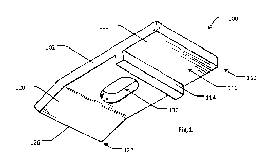
[0022] Figure 1 shows a perspective view of a clip, according to some
embodiments;
[0023] Figure 2 shows an exploded diagram illustrating installation of the
clip of
Figure 1 to assist in fastening first and second members to each other,
according to
some embodiments;
[0024] Figure 3 shows a cross-sectional view of the clip of Figure 1 installed
and
fastening the first and second members of Figure 2 to each other;
CA 03076686 2020-03-23
WO 2019/060940 PCT/AU2017/051050
[0025] Figure 4A shows a plan view of a clip according to some embodiments;
[0026] Figure 4B shows a side view of the clip of Figure 4A.
Description of Embodiments
[0027] Embodiments generally relate to clips for fastening members together
using
friction connections. Some embodiments relate to panel clips to assist in
fastening
panels to frames.
[0028] Referring to Figure 1, a clip 100 is shown according to some
embodiments.
The clip 100 may be used to assist in fastening first and second members to
each other.
For example, referring to Figures 2 and 3, in some applications the first
member 210
may comprise an element of a frame and the second member 220 may comprise a
panel.
[0029] The clip 100 comprises a plate 102 defining a first engaging portion
110 at a
first end 112 of the plate 102 for engaging the first member 210 and a second
engaging
portion 120 at a second end 122 of the plate 102 opposite the first end 112
for engaging
the second member 220. The plate 102 may further define a fastener aperture
130
located between the first engaging portion 110 and the second engaging portion
120.
[0030] The fastener aperture 130 may be configured to receive a fastener 230
to
connect the clip 100 to the second member 220. For example, referring to
Figures 2 and
3, in some applications, a mechanical fastener 230, such as a screw or bolt,
may be
used to connect the clip 100 to the second member 220.
[0031] The clip 100 is configured to be connected to the second member 220, by
the
fastener 230, such that the second engaging portion 120 is urged against the
second
member 220 and the first engaging portion 110 is urged against the first
member 210 to
form a friction connection between the first engaging portion 110 and the
first member
210.
CA 03076686 2020-03-23
WO 2019/060940 PCT/AU2017/051050
6
[0032] The clip 100 may comprise one or more projecting portions 114 extending
away from the plate 102 at or near the first engaging portion 110 between the
first and
second ends 112, 122 of the plate 102. The one or more projecting portions 114
are
configured to restrict rotation of the clip 100, once installed, by abutting
part of the first
member 210.
[0033] In some embodiments, the fastener aperture 130 may be defined by an
elongate slot, as shown in Figure 1. That is, the aperture 130 may be longest
in one
direction. A maximum diameter of the aperture 130 may be aligned along the
plate 102
with an axis extending between the first and second engaging portions 110,
120. This
may allow for small relative movements between the first and second members
210,
220 by allowing the fastener 230 to move along the length of the fastener
aperture 130
without compromising the connection between the clip 100 and the first and
second
members 210, 220.
[0034] In some embodiments, the first engaging portion 110 may be configured
to
engage a flange 212 of the first member 210. For example, referring to Figures
2 and 3,
the clip 100 may comprise a panel clip 100 configured to assist in fastening a
panel 220
to a frame element 210.
[0035] The frame element 210 may comprise a steel column having a flange 212
(such as the flange of an I- section profile, for example), and the clip 100
may be
configured such that, once installed, a contact surface 116 of the first
engaging portion
110 contacts a contact surface 216 of the flange 212. As the fastener 230 is
tightened to
connect the clip 100 to the panel 220, the second engaging portion 120 is
urged against
a contact surface 226 of the panel 220 and the first engaging portion 110 is
urged
against the flange 212 of the frame element 210, such that a friction
connection is
formed between the respective contacting surfaces 116, 216 of the first
engaging
portion 110 and the flange 212 of the frame element 210.
[0036] In some applications, a plane of the contact surface 226 of the second
member
or panel 220 may be offset from a plane of the contact surface 216 of the
first member
CA 03076686 2020-03-23
WO 2019/060940 PCT/AU2017/051050
7
or frame element 210. For example, in Figure 3, the offset distance between
the levels
of the contact surfaces 216, 226 corresponds to the thickness of the flange
212 which
directly abuts the flat contact surface 226 of the panel 220.
[0037] To account for the difference in the levels of the contact surfaces
216, 226, in
some embodiments, the second engaging portion 120 of the plate 102 may be
angled
relative to the rest of the plate 102, as shown in Figure 1. For example, a
plane of the
second engaging portion 120 may extend away from a plane of the first engaging
portion 110 at an obtuse angle. A contact edge 126 of the second engaging
portion 120
may be configured to engage the contact surface 226 the second member 220.
[0038] The angle between the planes of the first and second engaging portions
110,
120 may be configured such that, when the clip 100 is installed with the edge
126 of
the second engaging portion 120 engaging the contact surface 226 of the second
member or panel 220 the respective contact surfaces 116, 216 of the first
engaging
portion 110 and first member 210 contact each other in a substantially
parallel
configuration.
[0039] In some embodiments, the second engaging portion 120 may lie in the
same
plane as the rest of the plate 102 and may not be angled with respect to the
first
engaging portion 110. This configuration may be used in applications where the
contact
surfaces of the first and second members 210, 220 are level. For example, with
a panel
having an edge rebate to accommodate the flange of a frame element, such that
respective contact surfaces of the flange and the panel are level.
[0040] Referring again to Figures 2 and 3, the one or more projecting portions
114
may be configured to abut an edge 214 of the flange 212 of the frame element
210,
once installed, to restrict rotation of the clip 100 relative to the frame
element 210. The
one or more projecting portions 114 may extend away from the plate 102 by a
distance
that is less than the thickness of the flange 212 so that the one or more
projecting
portions do not contact the panel 220 and potentially restrict contact between
the
CA 03076686 2020-03-23
WO 2019/060940 PCT/AU2017/051050
8
respective contact surfaces 116, 216 of the first engaging portion 110 and the
flange
212.
[0041] The one or more projecting portions 114 may extend away from a surface
of
the plate 102 adjacent the contact surface 116. The one or more projecting
portions 114
may be arranged or oriented along a line adjacent the contact surface 116. The
line of
orientation may be substantially parallel to an edge of first end 112 of the
plate 102.
The line of orientation may be substantially perpendicular to a central axis
of the plate
102 extending between the first and second engaging portions 110, 120. In some
embodiments, the one or more projecting portions 114 may comprise an elongate
ridge
extending alongside at least part of the first engaging portion 110 of the
plate 102, as
shown in Figure 1. In some embodiments, the one or more projecting portions
114 may
comprise two or more projecting portions 114 spaced apart from one another at
or near
the first engaging portion 110.
[0042] The panel 220 may comprise a cast-in nut or ferrule 232 configured to
receive
and engage the fastener or bolt 230 to connect the clip 100 to the panel 220.
In some
applications, the fastener 230 may engage a drilled in anchor in the panel
220, or may
engage the material of the panel 220 (e.g., concrete) directly.
[0043] The clip 100 may be formed of any suitable material with sufficient
strength
and stiffness to transfer forces between the fastener 230 and the first and
second
members 210, 220 to provide a friction connection of sufficient strength for a
given
application. Some suitable materials may include metals, metal alloys, steel,
structural
steel, G250 grade structural steel or G350 grade structural steel, for
example.
[0044] The clip 100 may be formed from a plate by cutting, stamping, milling
or
drilling the fastener aperture 130; folding, deflecting or bending the second
engaging
portion 120 away from the plane of the first engaging portion 110 at an angle
(this
process may be omitted for flat plate embodiments); and forming the one or
more
projecting portions 114. In some embodiments, the one or more projecting
portions 114
may be formed by making cuts in the plate 102 and bending part of the plate
102 away
CA 03076686 2020-03-23
WO 2019/060940 PCT/AU2017/051050
9
from the plane of the first engaging portion 110 to form the projecting
portions 114. In
some embodiments, the one or more projecting portions 114 may be formed
separately
and then fixed to the plate 102 at or near the first engaging portion 110,
such as by
welding, for example.
[0045] In embodiments where the one or more projecting portions 114 comprise
an
elongate ridge (as shown in Figure 1, for example), the ridge may be formed as
a strip
having a rectangular or square profile and welded to the plate 102, for
example.
[0046] The clip 100 may be formed with different dimensions for different
applications. For example, the clip 100 may be approximately 150mm long from
the
first end 112 to the second end 122 and approximately 130mm wide. The
thickness of
the plate 102 may be approximately 8mm. The fastener aperture 130 may be
approximately 40mm long and 22mm wide. The one or more projecting portions 114
may extend away from the plate 102 by a distance of about 8mm. The angle
between
the plane of the first engaging portion 110 and the plane of the second
engaging portion
120 may be approximately 30 . The difference in the respective levels of the
contact
surface 116 of the first engaging portion 110 and the contact edge 126 of the
second
engaging portion 120 may be approximately 17mm. The first engaging portion 110
may be approximately 50mm long and approximately 130mm wide.
[0047] These dimensions are given as an example only, and the dimensions, and
relative proportions may vary significantly in different embodiments, such as
different
clips for different applications. For example, the length and width of the
clip 100 may
be varied to accommodate differently dimensioned contact surfaces 216 on
different
first members 210, or to adjust the degree of leverage between the fastener
230 and the
first and second engaging portions 110, 120. The plate thickness may be
increased or
decreased depending on the strength and stiffness required for a given
application. The
dimensions of the fastener aperture 130 may be adjusted to accommodate
different
fasteners 230. The distance that the one or projecting portions 114 extend
away from
the plate 102 may be adjusted depending on the contact area required between
the one
or more projecting portions 114 and the first member 210. The angle between
the plane
CA 03076686 2020-03-23
WO 2019/060940 PCT/AU2017/051050
of the first engaging portion 110 and the plane of the second engaging portion
120
and/or the difference in the respective levels of the contact surface 116 of
the first
engaging portion 110 and the contact edge 126 of the second engaging portion
120 may
be varied depending on the difference in the respective levels of the contact
surfaces
216, 226 of the first and second members 210, 220.
[0048] For example, in some embodiments, the clip 100 may be between 100mm and
300mm long from the first end 112 to the second end 122 and between 50mm and
200mm wide. The thickness of the plate 102 may be between 3mm and 20mm, or
between 5mm and lOmm. The fastener aperture 130 may be between 20mm and
100mm long and between lOmm and 50mm wide. The one or more projecting portions
114 may extend away from the plate 102 by a distance of between 2mm and 20mm,
or
between 5mm and lOmm. The angle between the plane of the first engaging
portion
110 and the plane of the second engaging portion 120 may be between 0 and 90
,
between 10 and 60 , or between 20 and 45 . The difference in the respective
levels of
the contact surface 116 of the first engaging portion 110 and the contact edge
126 of
the second engaging portion 120 may be between Omm and 50mm, between 5mm and
30mm, or between lOmm and 20mm. The first engaging portion 110 may be between
lOmm and 100mm long and between 50mm and 200mm wide.
[0049] Referring to Figures 4A and 4B, a clip 400 is shown according to some
embodiments. The clip 400 may have similar features to those described in
relation to
clip 100 and similar features are indicated with similar reference numerals.
The clip
400 may be formed in a similar manner with similar suitable materials as
described in
relation to clip 100.
[0050] The clip 400 comprises a plate 402 defining a first engaging portion
410 at a
first end 412 of the plate 402 for engaging the first member 210 and a second
engaging
portion 420 at a second end 422 of the plate 402 opposite the first end 412
for engaging
the second member 220. The plate 402 further defines a fastener aperture 430
located
between the first engaging portion 410 and the second engaging portion 420.
The
CA 03076686 2020-03-23
WO 2019/060940 PCT/AU2017/051050
11
fastener aperture 430 is be configured to receive a fastener 230 to connect
the clip 400
to the second member 220.
[0051] The clip 400 is configured to be connected to the second member 220, by
the
fastener 230, such that the second engaging portion 420 is urged against the
second
member 220 and the first engaging portion 410 is urged against the first
member 210 to
form a friction connection between the first engaging portion 410 and the
first member
210.
[0052] The clip 400 comprises one or more projecting portions 414 extending
away
from the plate 402 at or near the first engaging portion 410 between the first
and second
ends 412, 422 of the plate 402. The one or more projecting portions 414 are
configured
to restrict rotation of the clip 400, once installed, by abutting part of the
first member
210.
[0053] The clip 400 further defines a washer slot 440 alongside the fastener
aperture
430. The washer slot 440 is configured to receive part of a swageable washer
500 to
restrict rotation of the fastener 230 relative to the clip 400 once installed.
For example,
one such swageable washer is described in Australian Patent Number 2006294407
(International Application PCT/AU2006/001371), the disclosure of which is
hereby
incorporated by reference.
[0054] Referring to Figure 5, in some embodiments, the swageable washer 500
comprises a main washer body 530 defining an aperture (not shown) for the
fastener or
bolt 230 to pass through, and a cap 510 configured to cover a head of the bolt
230 to
restrict rotation of the bolt 230. The cap 510 comprises a plurality of
swageable tabs
512 arranged in an annular formation around an opening of the cap 510. The
swageable
tabs 512 are configured to be deformed by the bolt head when the cap 510 is
forced
down over the bolt head, thereby cooperating to engage and restrict rotation
of the bolt
230 relative to the washer 500. The washer 500 further comprises a tab 540
extending
from the body 530 of the washer 500, which is configured to engage part of the
clip
100, 400 to restrict relative rotation between the washer 500 and the clip
100, 400.
CA 03076686 2020-03-23
WO 2019/060940 PCT/AU2017/051050
12
[0055] In some embodiments, the tab 540 of the washer 530 may engage an edge
of
the clip 100, 400. In some embodiments, in which the clip 400 defines a washer
slot
440, the tab 540 of the washer 500 may engage the washer slot 440. For
example, the
washer slot 440 may receive at least part of the tab 530 of the washer 500,
and edges of
the washer slot 440 may restrict rotation of the washer tab 530, and washer
500,
relative to the clip 400.
[0056] In some embodiments, the clip 100, 400 may be supplied with the
swageable
washer 500. In some embodiments, the clip 100, 400 and washer 500 may also be
supplied with a fastener 230.
[0057] The described clips 100, 400 may have many different applications in
fastening a first member 210 to a second member 220. Some examples include
fastening rail way tracks to sleepers, fastening frame elements to
foundations, fastening
steel frame elements (such as columns or beams) to a concrete slab, fastening
a bracket
or other member to a panel (such as a concrete panel), or fastening a panel to
a frame
element.
[0058] As described in relation to Figures 2 and 3, the described clips 100,
400 may
be used to assist in fastening a concrete panel to a steel column, for
example.
[0059] A structure (such as a commercial or residential building or warehouse)
may
be constructed by erecting a steel frame on a concrete slab, and then
fastening a
plurality of pre-cast concrete panels to the steel frame. Each panel 220 may
be placed
against columns 210 of the frame, and then fastened to the columns 210 using
the clips
100, 400.
[0060] For example, a threaded end of a fastener or bolt 230 may be passed
through
the fastener aperture 130, 430 and rotated to engage the panel 220 and fasten
the clip
100, 400 to the panel 220. As the bolt 230 is tightened, the second engaging
portion
120, 420 is urged against the panel 220, and the first engaging portion
110,410 is urged
against the flange 212 of the column 210. The clip 100, 400 then acts as a
lever
CA 03076686 2020-03-23
WO 2019/060940 PCT/AU2017/051050
13
between the bolt 230, panel 220 and column 210, forming a friction connection
between the first engaging portion 110, 410 of the clip 100, 400 and the
flange 212 of
the column 210.
[0061] In some embodiments, the bolt 230 may be driven directly into the panel
220,
or into a predrilled hole in the panel 220 to directly engage the material of
the panel
220. In some embodiments, the panel 220 may comprise a cast-in nut or ferrule
to
engage the bolt 230, or the panel 220 may define a through-hole for the
threaded end of
the bolt 230 to pass through and engage with a nut on an opposite side of the
panel 220.
[0062] In some embodiments, the swageable washer 500 may be used to restrict
rotation of the bolt 230 once the clip 100, 400 has been installed. The
swageable
washer 500 may be located between a head of the bolt 230 and the clip 100, 400
before
fastening the clip 100, 400 to the panel 220. The washer 500 may then be
swaged onto
the bolt head to restrict rotation of the bolt 230 after fastening the clip
100, 400 to the
panel 220.
[0063] As described previously, some structures have been erected in the past
using
panel clips that are bolted to the panel and welded to the frame. These welded
joints
often crack and fail due to relative movement between the panel and the frame
due to
vibration or thermal expansion and contraction. In such cases, the described
panel clips
100, 400 of the present disclosure may be installed in existing structures to
replace or
complement existing panel clips (or other fasteners or connectors). This may
enhance
or improve the strength and/or durability of the connections between panels
and frames.
[0064] It will be appreciated by persons skilled in the art that numerous
variations
and/or modifications may be made to the above-described embodiments, without
departing from the broad general scope of the present disclosure. The present
embodiments are, therefore, to be considered in all respects as illustrative
and not
restrictive.