Note: Descriptions are shown in the official language in which they were submitted.
CA 03078346 2020-04-02
1
DESCRIPTION
CORE SHEET AND METHOD OF MANUFACTURING SAME
[TECHNICAL FIELD]
[0001]
The present invention relates to core sheets which have an annular core
back portion and a plurality of tooth portions extending from the core back
portion
toward a radial center thereof, and to methods of manufacturing the core
sheets.
[BACKGROUND ART]
[0002]
In rotating electric machines such as electric generators and electric motors,
there are employed stator cores which are formed by laminating a plurality of
annular core sheets each having an annular core back portion and tooth
portions. To
achieve reduction in the sizes of the rotating electric machines and
improvement in
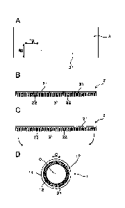
the performances, such as the outputs, of the rotating electric machines, it
is desired
to control the easy directions of magnetization in the core sheets each of
which is
formed of a magnetic steel sheet. Specifically, it is desired to have the easy
directions of magnetization in the tooth portions, each of which extends in a
radial
direction of the annular core sheet, coinciding with the respective extending
directions of the tooth portions. In addition, an easy direction of
magnetization is
also referred to as the direction of an easy axis of magnetization.
[0003]
For example, in Patent Document 1, there is disclosed a technique of
manufacturing a core sheet by: blanking out a band-shaped sheet piece, which
has
a core back portion and tooth portions, from a grain-oriented magnetic steel
sheet
having a single easy direction of magnetization; and then rolling the sheet
piece into
an annular shape. With this technique, it is possible to manufacture a core
sheet
CA 03078346 2020-04-02
2
where the easy directions of magnetization in the tooth portions coincide with
the
respective extending directions of the tooth portions.
[PRIOR ART LITERATURE]
[PATENT LITERATURE]
[0004]
[PATENT DOCUMENT 1] Japanese Patent Application Publication
No. JP H09-92561 A
[ SUMMARY OF THE INVENTION]
[PROBLEMS TO BE SOLVED BY THE INVENTION]
[0005]
However, the grain-oriented magnetic steel sheet has the single easy
direction of magnetization. Therefore, when the core sheet is manufactured by
blanking out the sheet piece so as to have the extending direction of each of
the
tooth portions of the sheet piece coinciding with the easy direction of
magnetization
of the grain-oriented magnetic steel sheet and then rolling the sheet piece
into the
annular shape, the core back portion of the core sheet has easy directions of
magnetization coinciding with the extending directions of the tooth portions
of the
core sheet. Actually, the desired easy direction of magnetization in the
annular core
back portion is the circumferential direction.
[0006]
In the core back portion, if the ease of magnetization is high in the
directions perpendicular to the circumferential direction, i.e., high in the
extending
directions of the tooth portions, magnetization in a magnetic circuit of the
stator
core will become difficult, lowering the magnetic properties. That is, in the
core
sheet, the magnetic properties will become high in the tooth portions, but low
in the
core back portion.
CA 03078346 2020-04-02
3
[0007]
On the surface of a grain-oriented magnetic steel sheet, there is generally
formed an insulation coating. By the insulation coating, insulation properties
are
imparted to the grain-oriented magnetic steel sheet. Moreover, by the
insulation
coating, tension is applied in the easy direction of magnetization of the
grain-
oriented magnetic steel sheet, lowering the iron loss. That is, by the
insulation
coating, the magnetic reluctance is lowered and the magnetic properties are
improved in the easy direction of magnetization.
[0008]
However, while the lowering of the magnetic reluctance in the easy
direction of magnetization is advantageous to improvement of the magnetic
properties in the tooth portions, it is disadvantageous to improvement of the
magnetic properties in the core back portion. This is because in the core back
portion, it is desired to improve the magnetic properties in the
circumferential
direction that is perpendicular to the easy direction of magnetization.
Accordingly,
there is room for further improvement of the magnetic properties in the entire
core
sheet; thus further improvement is desired for achieving reduction in the
sizes of
the rotating electric machines and improvement in the performances, such as
the
outputs, of the rotating electric machines.
[0009]
The present invention has been made in view of the above problems, and
aims to provide a core sheet, which has excellent magnetic properties in both
the
core back portion and the tooth portions, and a method of manufacturing the
core
sheet.
[MEANS FOR SOLVING THE PROBLEMS]
[0010]
CA 03078346 2020-04-02
4
According to one aspect of the present invention, there is provided a
method of manufacturing a core sheet (1). The core sheet has an annular core
back
portion (11) and a plurality of tooth portions (12) extending from the core
back
portion toward a radial center (0) thereof. The method includes:
a blanking step of blanking out a sheet piece (2) from a grain-oriented
magnetic steel sheet (3), the grain-oriented magnetic steel sheet having an
easy
direction (RD) of magnetization in one in-plane direction and an insulation
coating
(31) formed on its surface to apply tension in the easy direction of
magnetization,
the sheet piece having a band-shaped core back portion (21) extending in a
perpendicular direction (TD) to the easy direction of magnetization and a
plurality
of parallel tooth portions (22) extending, from the band-shaped core back
portion,
parallel to the easy direction of magnetization;
a rolling step of rolling the sheet piece, with the parallel tooth portions
being on an inner side, into an annular shape, thereby obtaining the core
sheet
having the core back portion and the tooth portions; and
a removing step of at least partially removing the insulation coating on the
band-shaped core back portion of the sheet piece or the insulation coating on
the
core back portion of the core sheet.
[0011]
According to another aspect of the present invention, there is provided a
method of manufacturing a core sheet (1). The core sheet has an annular core
back
portion (11) and a plurality of tooth portions (12) extending from the core
back
portion toward a radial center (0) thereof. The method includes:
a removing step of at least partially removing, from a grain-oriented
magnetic steel sheet (3) having an easy direction (RD) of magnetization in one
in-
plane direction and an insulation coating (31) formed on its surface to apply
tension
CA 03078346 2020-04-02
in the easy direction of magnetization, the insulation coating on a region
(32) for
forming a band-shaped core back portion which extends in a perpendicular
direction (TD) to the easy direction of magnetization;
a blanking step of blanking out a sheet piece (2) from the grain-oriented
5 magnetic steel sheet, the sheet piece having a band-shaped core back
portion (21)
present in the region for forming a band-shaped core back portion and a
plurality
of parallel tooth portions (22) extending, from the band-shaped core back
portion,
parallel to the easy direction of magnetization; and
a rolling step of rolling the sheet piece, with the parallel tooth portions
being on an inner side, into an annular shape, thereby obtaining the core
sheet
having the core back portion and the tooth portions.
[0012]
According to yet another aspect of the present invention, there is provided
a core sheet (1). The core sheet has:
an annular core back portion (11); and
a plurality of tooth portions (12) extending from the core back portion
toward a radial center (0) thereof,
wherein
the core back portion and the tooth portions are formed of a grain-oriented
magnetic steel sheet (3) to have an extending direction (L) of each of the
tooth
portions coinciding with an easy direction (RD) of magnetization of the grain-
oriented magnetic steel sheet,
the tooth portions have an insulation coating (31) that applies tension in
the easy direction of magnetization of the grain-oriented magnetic steel
sheet, and
the core back portion does not have the insulation coating.
CA 03078346 2020-04-02
6
[ADVANTAGEOUS EFFECTS OF THE INVENTION]
[0013]
In the above manufacturing methods, the parallel tooth portions are formed
each of which extends parallel to the easy direction of magnetization of the
grain-
.. oriented magnetic steel sheet; the sheet piece is rolled, with the parallel
tooth
portions being on the inner side, into an annular shape. Consequently, in the
core
back portion and the tooth portions, it becomes possible to have the easy
directions
of magnetization coinciding with radial directions of the annular core sheet.
As a
result, it becomes possible to lower the magnetic reluctance of the tooth
portions
.. and improve the magnetic properties of the tooth portions.
[0014]
On the other hand, in the core back portion, the desired easy direction
of magnetization is actually the circumferential direction of the annular core
back portion. Therefore, in the core back portion, if the ease of
magnetization
is high in the directions perpendicular to the circumferential direction,
i.e.,
high in the extending directions of the tooth portions, the magnetic
reluctance
in the circumferential direction will become high and thus magnetization will
become difficult.
[0015]
The grain-oriented magnetic steel sheet is manufactured such that tension
is applied in the easy direction of magnetization during the firing of the
insulation
coating. Consequently, the iron crystals are extended in micron order in the
easy
direction of magnetization. Moreover, the iron crystals generally have a
property
such that they extend upon application of a magnetic field in the easy
direction of
.. magnetization. Therefore, having the iron crystals extended in the easy
direction of
magnetization in advance by the tension applied by the insulation coating in
the
CA 03078346 2020-04-02
7
easy direction of magnetization, no energy is needed to deform the iron
crystals
during application of a magnetic field; thus it becomes easy for the grain-
oriented
magnetic steel sheet to be magnetized (i.e., the magnetic properties are
enhanced)
in the easy direction of magnetization. In contrast, in the perpendicular
direction to
the easy direction of magnetization, the magnetic properties are lowered due
to
strain caused by the tension applied by the insulation coating in the easy
direction
of magnetization.
In the above manufacturing methods, the insulation coating on the core
back portion is at least partially removed in the removing step. Consequently,
it
becomes possible to relieve or eliminate the tension in the easy direction of
magnetization which has been applied to the core back portion by the
insulation
coating. As a result, in the core back portion, though the magnetic properties
are
lowered (i.e., the magnetic reluctance is increased) in the extending
directions of
the tooth portions (i.e., in the radial directions of the core sheet), the
magnetic
.. properties are improved (i.e., the magnetic reluctance is lowered) in the
circumferential direction of the core sheet. That is, it becomes possible to
improve
the magnetic properties of the core back portion in the circumferential
direction
which is the desired direction. On the other hand, in the tooth portions, with
the
insulation coating remaining thereon, it becomes possible to prevent the
magnetic
.. properties in the radial directions of the core sheet from being lowered.
[0016]
Accordingly, with the above manufacturing methods, it becomes
possible to manufacture the core sheet which has the magnetic properties of
the core back portion in the circumferential direction improved while
.. maintaining the excellent magnetic properties of the tooth portions in the
radial
directions of the core sheet. In other words, it becomes possible to provide
the
CA 03078346 2020-04-02
8
manufacturing methods with which the magnetic properties of the entire core
sheet can be improved.
[0017]
Moreover, the core sheet, which has the insulation coating on the tooth
.. portions but no insulation coating on the core back portion, is excellent
in both
the magnetic properties of the tooth portions in the respective extending
directions thereof and the magnetic properties of the core back portion in the
circumferential direction. Specifically, in the tooth portions, since the
tension
applied to the grain-oriented magnetic steel sheet by the insulation coating
is
maintained, the ease of magnetization in the radial directions of the core
sheet
is kept at a high level. On the other hand, in the core back portion, since
the
tension applied to the grain-oriented magnetic steel sheet by the insulation
coating is relieved or eliminated, the ease of magnetization in the radial
directions of the core sheet is lowered while the ease of magnetization in the
circumferential direction of the annular core back portion is improved.
[0018]
As above, the core sheet, which has the insulation coating on the tooth
portions but no insulation coating on the core back portion, is excellent in
magnetic properties in the desired directions in both the tooth portions and
the
core back portion.
In addition, the reference signs in parenthesis recited in the claims and the
"means for solving the problems" section only represent the correspondence
with
specific means described in the following embodiments, and should not be taken
to
limit the technical scope of the present invention.
[BRIEF DESCRIPTION OF THE DRAWINGS]
[0019]
CA 03078346 2020-04-02
9
FIG. IA is a plan view of a grain-oriented magnetic steel sheet according
to a first embodiment.
FIG. I B is a plan view of a sheet piece according to the first embodiment.
FIG. 1C is a plan view of the sheet piece according to the first embodiment,
where an insulation coating has been removed from a band-shaped core back
portion.
FIG. 1D is a plan view of a core sheet according to the first embodiment,
which has a core back portion from which the insulation coating has been
removed.
FIG. 2 is a cross-sectional view of the grain-oriented magnetic steel sheet
according to the first embodiment.
FIG. 3A is a schematic view illustrating the manner of irradiating a laser
beam onto the insulation coating using a laser peening device according to the
first
embodiment.
FIG. 3B is a schematic view illustrating the removal of the insulation
coating by the irradiation of the laser beam according to the first
embodiment.
FIG. 4 is an enlarged plan view of the core sheet according to the first
embodiment, where the insulation coating has been removed from the core back
portion.
FIG. 5 is an enlarged plan view of a core sheet according to the first
embodiment, where the insulation coating has been partially removed from the
core
back portion.
FIG. 6 is an enlarged plan view of a core sheet according to the first
embodiment, illustrating various regions in the core back portion.
FIG. 7A is a plan view of a grain-oriented magnetic steel sheet according
to a second embodiment.
FIG. 7B is a plan view of a sheet piece according to the second
CA 03078346 2020-04-02
embodiment.
FIG. 7C is a plan view of a core sheet, which has an insulation coating,
according to the second embodiment.
FIG. 7D is a plan view of the core sheet according to the second
5 embodiment, where the insulation coating has been removed from a core back
portion.
FIG. 8A is a plan view of a grain-oriented magnetic steel sheet according
to a third embodiment, where an insulation coating has been removed from a
region
for forming a core back portion.
10 FIG. 8B is a plan view of a sheet piece according to the third
embodiment,
which has a band-shaped core back portion from which the insulation coating
has
been removed.
FIG. 8C is a plan view of a core sheet according to the third embodiment,
which has a core back portion from which the insulation coating has been
removed.
FIG. 9A is a plan view of a grain-oriented magnetic steel sheet according
to a first comparative embodiment.
FIG. 9B is a plan view of a sheet piece according to the first comparative
embodiment.
FIG. 9C is a plan view of a core sheet, which has an insulation coating,
according to the first comparative embodiment.
FIG. 10 is a graph illustrating the relationship between the magnetizing
force and the magnetic flux density of a grain-oriented magnetic steel sheet
before
and after removing an insulation coating therefrom according to a first
experimental
example.
FIG. 11 is an enlarged plan view of a core sheet according to a second
experimental example, illustrating various dimensions of a core back portion
and
CA 03078346 2020-04-02
11
tooth portions of the core sheet.
FIG. 12 is an explanatory diagram illustrating the relationship between r/0
and the magnetic reluctance in the core sheet according to the second
experimental
example.
FIG. 13 is an enlarged plan view of a core sheet according to a first
modification, which has a core back portion where a band-shaped coating-
remaining region is formed.
FIG. 14 is an enlarged plan view of a core sheet according to the first
modification, which has a core back portion where both rhomboid coating-
remaining regions and band-shaped coating-remaining regions are formed.
FIG. 15 is an enlarged plan view of a core sheet according to a fourth
embodiment, which has a core back portion where convex coating-remaining
regions are formed, each of the convex coating-remaining regions having a
protruding part that extends toward one tooth portion of the core sheet.
FIG. 16 is an enlarged plan view of a core sheet according to a second
modification, which has a core back portion where circular coating-remaining
regions are formed.
FIG. 17 is an enlarged plan view of a core sheet according to the second
modification, which has a core back portion where elliptical coating-remaining
regions are formed, each of the elliptical coating-remaining regions having
its major
axis oriented in the circumferential direction.
FIG. 18 is an enlarged plan view of a core sheet according to the second
modification, which has a core back portion where elliptical coating-remaining
regions are formed, each of the elliptical coating-remaining regions having
its major
axis oriented in the extending direction of one tooth portion of the core
sheet.
FIG. 19 is an enlarged plan view of a core sheet according to the second
CA 03078346 2020-04-02
12
modification, which has a core back portion where fan-shaped coating-remaining
regions are formed.
FIG. 20 is an enlarged plan view of a core sheet according to the second
modification, which has a core back portion where mountain-shaped coating-
remaining regions are formed.
FIG. 21 is an enlarged plan view of a core sheet according to the second
modification, which has a core back portion where rod-shaped coating-remaining
regions are formed.
FIG. 22 is an enlarged plan view of a core sheet according to a third
modification, which has a core back portion where rod-shaped coating-remaining
regions are formed in tooth portion-extending regions.
FIG. 23 is an enlarged plan view of a core sheet according to the third
modification, which has a core back portion where rod-shaped coating-remaining
regions are formed in both tooth portion-extending regions and non-tooth
portion-
extending regions.
FIG. 24 is an enlarged plan view of a core sheet according to the third
modification, which has a core back portion where fan-shaped coating-remaining
regions are formed continuously in the circumferential direction.
FIG. 25 is an enlarged plan view of a core sheet according to the third
modification, which has a core back portion where semielliptical non-coating-
forming regions are formed continuously in the circumferential direction.
[EMBODIMENTS FOR CARRYING OUT THE INVENTION]
[0020]
(First Embodiment)
An embodiment relating to a manufacturing method of a core sheet
will be described with reference to FIGS. 1-6. In the present embodiment, as
CA 03078346 2020-04-02
13
illustrated in FIG. 1, a core sheet 1 is manufactured by performing a removing
step and a rolling step after a blanking step. The core sheet 1 has an annular
core back portion 11 and a plurality of tooth portions 12 extending from the
core back portion 11 toward a radial center 0 thereof (i.e., radially inward).
[0021]
In the present embodiment, the core sheet 1 is manufactured by
performing the blanking step, the removing step and the rolling step. Each of
the steps is outlined as follows.
[0022]
As illustrated in FIG. 1A and FIG. 1B, in the blanking step, a sheet
piece 2 is blanked out from a grain-oriented magnetic steel sheet 3. The sheet
piece 2 has a band-shaped core back portion 21 extending in a perpendicular
direction TD to the easy direction RD of magnetization of the sheet piece 2
and a plurality of parallel tooth portions 22 extending parallel to the easy
direction RD of magnetization.
[0023]
As illustrated in FIG. 1B and FIG. 1C, in the removing step, an
insulation coating 31 on the band-shaped core back portion 21 of the sheet
piece 2 is at least partially removed. As illustrated in FIG. 1C and FIG. 1D,
in
the rolling step, the sheet piece 2 is rolled, with the parallel tooth
portions 22
being on the inner side, into an annular shape. Consequently, the core sheet 1
is obtained which has the core back portion 11 and the tooth portions 12.
Hereinafter, each of the steps will be described in detail.
[0024]
As illustrated in FIG. 1A, the grain-oriented magnetic steel sheet 3 has
the easy direction RD of magnetization in one in-plane direction. That is, the
CA 03078346 2020-04-02
14
grain-oriented magnetic steel sheet 3 is a magnetic steel sheet which has a
single easy direction RD of magnetization coinciding with one of in-plane
directions of the plate-shaped magnetic steel sheet. The in-plane directions
denote directions perpendicular to a thickness direction Z of the magnetic
steel
sheet. In general, the easy direction RD of magnetization is parallel to the
rolling direction. Accordingly, the perpendicular direction TD to the easy
direction RD of magnetization is generally perpendicular to the rolling
direction. In addition, the grain-oriented magnetic steel sheet 3 may be
implemented by a commercially available grain-oriented magnetic steel sheet,
such as 23ZH85 produced by Nippon Steel Corporation.
[0025]
As illustrated in FIG. 2, the grain-oriented magnetic steel sheet 3
includes a steel sheet 30 and an insulation coating 31 formed on the surface
of
the steel plate 30. The insulation coating 31 is a coating which imparts
insulation properties to the grain-oriented magnetic steel sheet 3 while
applying tension in the easy direction RD of magnetization of the steel sheet
30 to reduce iron loss of the grain-oriented magnetic steel sheet 3. In
addition,
the insulation coating 31 may be formed on both faces of the steel plate 30 as
illustrated in FIG. 2, or on only one face of the steel plate 30.
[0026]
The determination as to whether the insulation coating 31 is a coating
which applies tension can be made by checking whether the steel sheet is
warped upon removal of the insulation coating 31 from the grain-oriented
magnetic steel sheet 3. Alternatively, the determination can be made by
.. comparing the iron loss of the grain-oriented magnetic steel sheet 3 having
the
insulation coating 31 formed thereon and the iron loss of the grain-oriented
CA 03078346 2020-04-02
magnetic steel sheet 3 from which the insulation coating 31 has been removed.
That is, when at least one of warp of the steel sheet and change in the iron
loss
of the steel sheet has occurred upon removal of the insulation coating 31, the
insulation coating 31 is determined to be a coating which applies tension.
5 [0027]
In the case of making the determination by checking warp, the
insulation coating 31 on one face of the grain-oriented magnetic steel sheet 3
is removed while the insulation coating 31 on the other face that is on the
opposite side to the removal face is left without being removed. Then, if warp
10 of the steel sheet 30 has occurred on the removal face side, the
insulation
coating 31 is determined to be a coating which applies tension. On the other
hand, in the case of making the determination by checking change in the iron
loss, two iron-loss test pieces are taken in the easy direction RD of
magnetization respectively from the grain-oriented magnetic steel sheet 3
15 having the insulation coating 31 formed thereon and the grain-oriented
magnetic steel sheet 3 from which the insulation coating 31 has been removed.
Then, the iron losses of the test pieces are measured by a single sheet tester
and compared with each other. If the iron loss of the grain-oriented magnetic
steel sheet 3 in the easy direction RD of magnetization has been lowered by
removal of the insulation coating 31, the insulation coating 31 is determined
to be a coating which applies tension.
[0028]
The insulation coating 31 is formed of ceramic, glass, a metal oxide
or the like. In the present specification, the insulation coating 31 is a
concept
which excludes passive films that may be formed on the surfaces of metals
such as steel. The insulation coating 31 may be formed in a single layer, or
two
CA 03078346 2020-04-02
16
or more layers. The thickness of the insulation coating 31 is, for example,
0.1-
10,um. In the case of the insulation coating 31 being formed in a plurality of
layers, the thickness of the insulation coating 31 is equal to the sum of
thicknesses of all the layers. On the other hand, the thickness of the steel
sheet
30 is, for example, 0.1-1.0mm. It is preferable that the thickness of the
steel
sheet 30 is 0.15-0.35mm.
[0029]
As illustrated in FIG. lA and FIG. 1B, in the blanking step, the sheet
piece 2 is blanked out from the grain-oriented magnetic steel sheet 3.
Specifically, the sheet piece 2 is blanked out so as to have the band-shaped
core back portion 21 extending in the perpendicular direction TD to the easy
direction RD of magnetization of the grain-oriented magnetic steel sheet 3.
That is, the longitudinal direction of the band-shaped core back portion 21 is
parallel to the perpendicular direction TD to the easy direction RD of
.. magnetization. On the other hand, the parallel tooth portions 22 extend
parallel
to the easy direction RD of magnetization of the grain-oriented magnetic steel
sheet 3. In addition, as illustrated in FIG. 1B, the sheet piece 2 is comb-
shaped
to have the parallel tooth portions 22 formed in the shape of comb teeth.
[0030]
In the present specification, the term "perpendicular direction"
encompasses not only the direction of 90 but also directions close to the
direction of 90 in appearance. Similarly, the term "parallel direction"
encompasses not only the direction of 180 or 360 but also directions close
to
the direction of 180 or 360 in appearance.
[0031]
Next, in the removing step, the insulation coating 31 on the band-
CA 03078346 2020-04-02
17
shaped core back portion 21 is removed. The insulation coating 31 on the band-
shaped core back portion 21 may be either completely removed, or partially
removed to have part of the insulation coating 31 left thereon. Here, the
expression "completely removed" denotes that substantially all the insulation
coating 31 is removed. In addition, inevitable residual traces of the
insulation
coating 31, which cannot be avoided during performing the removing step,
may be tolerated.
[0032]
In the case of the insulation coating 31 on the band-shaped core back
portion 21 being completely removed, the tension applied by the insulation
coating 31 to the band-shaped core back portion 21 disappears or becomes
sufficiently low. Consequently, in the band-shaped core back portion 21, the
magnetic reluctance in the easy direction RD of magnetization is increased
while the magnetic reluctance in the perpendicular direction TD is lowered. As
.. a result, it becomes possible to improve the magnetic properties of the
core
back portion 11 of the core sheet 1 in the circumferential direction C.
[0033]
On the other hand, in the case of the insulation coating 31 on the band-
shaped core back portion 21 being partially removed, part of the insulation
coating 31 remains on the band-shaped core back portion 21. Consequently, it
becomes possible to have part of the insulation coating 31, which has
insulation properties, remaining on the core back portion 11 of the core sheet
1. Thus, when a plurality of core sheets 1 are laminated to form, for example,
a stator core of a rotating electric machine, it is possible to prevent or
suppress
electrical insulation between the core back portions 11 of the core sheets 1
from being lowered. As a result, it is possible to suppress eddy current loss
in
CA 03078346 2020-04-02
18
the core back portions II of the core sheets 1. Moreover, by partially
removing
the insulation coating 31 on the band-shaped core back portion 21, it is also
possible to lower the tension applied to the band-shaped core back portion 21
and thus possible to improve the magnetic properties in the circumferential
direction C. In addition, the effect of removing the insulation coating 31
from
the band-shaped core back portion 21 on improvement of the magnetic
properties of the core back portion 11 of the core sheet 1 in the
circumferential
direction C is considered to be higher in the case of completely removing the
insulation coating 31 than in the case of partially removing the insulation
coating 31.
[0034]
In the case of the insulation coating 31 being formed on both the faces
of the steel plate 30, it is possible to remove the insulation coating 31
either
from both the faces or from only one of the faces while leaving it on the
other
face. It is preferable to remove the insulation coating 31 from both the faces
of the steel plate 30. In this case, it is possible to further enhance the
effect of
removing the insulation coating 31 on improvement of the magnetic properties
as described above.
[0035]
The insulation coating 31 may be removed by laser peening, shot
peening, water jet peening, ultrasonic peening, electron-beam machining,
grinding, or an agent such as an acid or alkali. In addition, methods of
removing the insulation coating 31 are not limited to the above.
[0036]
It is preferable that the insulation coating 31 is removed by laser
peening, shot peening or water jet peening. It is further preferable that the
'
CA 03078346 2020-04-02
19
insulation coating 31 is removed by laser peening. In this case, the removal
accuracy is improved so that when partially removing the insulation coating
31, it is easy to form a coating-remaining region 111 in a desired shape.
Moreover, in the case of the insulation coating 31 being removed by laser
peening or shot peening, the removing step is performed in the atmosphere,
preventing rust from being produced. Moreover, in the case of the insulation
coating 31 being removed by laser peening or water jet peening, it is
unnecessary to use grinding media that may cause intrusion of foreign
substances; thus it is possible to suppress intrusion of foreign substances.
Furthermore, in the case of the insulation coating 31 being removed by laser
peening, it is possible to perform the peening process as an in-line process
at
high speed.
[0037]
As illustrated in FIG. 3A and FIG. 3B, in the case of removing the
.. insulation coating 31 by laser peening, a laser beam 40 is irradiated from
a
nozzle 41 of a laser peening device onto the band-shaped core back portion 21
of the sheet piece 2. By the irradiation of the laser beam 40, the insulation
coating 31 on the band-shaped core back portion 21 of the sheet piece 2 is
removed. The irradiation position can be changed by changing the relative
position between the nozzle 41 and the band-shaped core back portion 21.
Consequently, the insulation coating 31 on the band-shaped core back portion
21 can be removed either completely or partially.
[0038]
In the removing step, it is preferable to have the insulation coating 31
on the parallel tooth portions 22 left without being removed. In this case,
the
tension applied by the insulation coating 31 to the parallel tooth portions 22
is
CA 03078346 2020-04-02
maintained; thus the magnetic reluctance of the parallel tooth portions 22 in
the easy direction RD of magnetization can be kept low.
[0039]
Next, the rolling step is performed. In FIG. 1C, the two arrows
5 extending downward respectively from the two ends of the sheet piece 2
indicate the direction of rolling the sheet piece 2 in the rolling step. As
illustrated in FIG. 1C and FIG. 1D, in the rolling step, a rolling process is
performed to roll the sheet piece 2, with the parallel tooth portions 22 being
on the inner side, into an annular shape. Since the sheet piece 2 is curled,
the
10 rolling process may also be referred to as curling process.
[0040]
In the rolling step, the band-shaped core back portion 21 of the sheet
piece 2 is transformed into the annular core back portion 11 of the core sheet
1 while the parallel tooth portions 22 of the sheet piece 2 is transformed
into
15 the tooth portions 12 of the core sheet 1. In addition, the rolling
process is
performed so as to have the extending direction L of each of the tooth
portions
12 oriented toward the radial center 0 of the annular core back portion 11.
[0041]
As in the present embodiment, it is preferable for the rolling step to be
20 performed after the removing step. In this case, it is possible to
suppress or
prevent the insulation coating 31 from being crushed in the rolling step.
Specifically, in the rolling step, tensile elongation occurs in an outer
peripheral
part of the band-shaped core back portion 21 while compressive strain occurs
in an inner peripheral part of the band-shaped core back portion 21 during the
rolling process. At this time, if there remains the insulation coating 31 on
the
outer peripheral part and/or the inner peripheral part of the band-shaped core
CA 03078346 2020-04-02
21
back portion 21, the insulation coating 31 may be crushed and thus crushed
powder may be produced. As described above, in the removing step, the
insulation coating 31 is completely removed from the band-shaped core back
portion 21 or partially removed from the outer peripheral part and/or the
inner
.. peripheral part of the band-shaped core back portion 21. Consequently, it
becomes possible to prevent or suppress crushed powder from being produced
in the subsequent rolling step. As a result, it becomes possible to prevent a
failure from occurring in the rolling machine due to crushed powder; thus it
becomes possible to prevent the sheet piece 2 from being jammed in the rolling
machine during the rolling process and to prevent the core sheet 1 from being
damaged.
[0042]
An annealing step may be performed after the rolling step. In the
annealing step, the core sheet 1 is heated. By performing the annealing step,
the core sheet 1 can be recrystallized. The heating temperature in the
annealing
step may be suitably adjusted according to the material composition. For
example, the heating temperature may be adjusted in a range of, for example,
700-1000 C. The annealing step is an arbitrary step and may be performed with
arbitrary timing. That is, the annealing step may or may not be included in
the
manufacturing method of the core sheet 1 according to the present embodiment.
Moreover, the annealing step may alternatively be performed before the rolling
step. For example, the annealing step may be performed on the core sheet 2
before or after the removing step.
[0043]
The core sheet 1 can be manufactured as described above. In the case
of the insulation coating 31 on the band-shaped core back portion 21 being
CA 03078346 2020-04-02
22
completely removed in the removing step, it is possible to obtain the core
sheet
1 which has no insulation coating 31 on the core back portion 11 as
illustrated
in FIG. 4. On the other hand, in the case of the insulation coating 31 on the
band-shaped core back portion 21 being partially removed in the removing step,
it is possible to obtain the core sheet 1 which has the core back portion 11
where there are formed both non-coating-forming regions 112 and coating-
remaining regions 111 as illustrated in FIG. 5. Each of the non-coating-
forming regions 112 is a region from which the insulation coating 31 has been
removed. Each of the coating-remaining regions 111 is a region in which the
insulation coating 31 remains. The formation pattern of the non-coating-
forming regions 112 and the coating-remaining regions 111 illustrated in FIG.
5 is merely an example, and may be modified, for example, as illustrated in
the fourth embodiment and the first to the fourth modifications which will be
described later.
[0044]
In the manufacturing method according to the present embodiment, as
illustrated in FIG. lA to FIG. 1D, the sheet piece 2 is blanked out from the
grain-oriented magnetic steel sheet 3. The sheet piece 2 has the parallel
tooth
portions 22 extending parallel to the easy direction RD of magnetization and
the band-shaped core back portion 21 extending in the perpendicular direction
TD to the easy direction RD of magnetization. Then, the sheet piece 2 is
rolled,
with the parallel tooth portions 22 being on the inner side, into an annular
shape. Consequently, as illustrated in FIG. 4 and FIG. 5, in each of the tooth
portions 12 of the core sheet 1 obtained by the above manufacturing method,
it becomes possible to have the easy direction RD of magnetization coinciding
with the extending direction L of the tooth portion 12, i.e., with a direction
CA 03078346 2020-04-02
23
toward the radial center 0 of the annular core sheet 1. As a result, it
becomes
possible to improve the magnetic properties of the tooth portions 12. In
addition, while the easy direction RD of magnetization is indicated with a
dashed-line arrow in FIG. 4, it is not indicated in FIG. 5 where it is the
same
as in FIG. 4.
[0045]
On the other hand, in the core back portion 11, the desired easy
direction RD of magnetization is actually the circumferential direction C of
the annular core back portion 11. Therefore, in the core back portion 11, if
the
ease of magnetization is high in the directions perpendicular to the
circumferential direction C, i.e., high in the extending directions L of the
tooth
portions 12, the magnetic reluctance in the circumferential direction C will
become high and thus magnetization will become difficult. That is, the
magnetic properties of the core back portion 11 will be lowered.
[0046]
In the manufacturing method according to the present embodiment, as
illustrated in FIG. 1B and FIG. 1C, the insulation coating 31 on the core back
portion 11 is at least partially removed in the removing step. Consequently,
it
becomes possible to relieve or eliminate the tension in the easy direction RD
of magnetization which has been applied to the core back portion 11 by the
insulation coating 31.
[0047]
Accordingly, in the core back portion 11, the magnetic properties in
the extending directions L of the tooth portions 12, i.e., in the radial
directions
of the core sheet 1 are lowered, making it possible to lower the magnetic
reluctance and thereby improve the magnetic properties in the circumferential
CA 03078346 2020-04-02
24
direction C of the annular core sheet 1. On the other hand, in the tooth
portions
12, with the insulation coating 31 remaining thereon, it becomes possible to
prevent the magnetic properties in the radial directions of the core sheet 1
from
being lowered.
[0048]
As above, with the manufacturing method according to the present
embodiment, it becomes possible to manufacture the core sheet 1 which has
the magnetic properties of the core back portion 11 in the circumferential
direction C improved while maintaining the excellent magnetic properties of
the tooth portions 12 in the radial directions of the core sheet 1. That is,
it
becomes possible to improve the magnetic properties of the entire core sheet
1.
[0049]
Moreover, the core sheet 1, which has the insulation coating 31 on the
tooth portions 12 but no insulation coating 31 on the core back portion 11 as
illustrated in FIG. 4, is excellent in both the magnetic properties of the
tooth
portions 12 in the respective extending directions L thereof and the magnetic
properties of the core back portion 11 in the circumferential direction C.
Specifically, in the tooth portions 12, since the tension applied to the grain-
oriented magnetic steel sheet 3 by the insulation coating 31 is maintained,
the
ease of magnetization in the radial directions of the core sheet 1 is kept at
a
high level. On the other hand, in the core back portion 11, since the tension
applied to the grain-oriented magnetic steel sheet 3 by the insulation coating
31 is relieved or eliminated, the ease of magnetization in the radial
directions
of the core sheet 1 is lowered while the ease of magnetization in the
circumferential direction C of the annular core back portion 11 is improved.
CA 03078346 2020-04-02
[0050]
The above expression "has no insulation coating on the core back
portion" denotes that no insulation coating 31 is formed on substantially all
regions of the core back portion 11. However, inevitable residual traces of
the
5 .. insulation coating 31, which cannot be avoided during performing the
above-
described removing step, may be tolerated. Such residual is generally minute.
[0051]
It is preferable that the tooth portions 12 have, substantially in their
entirety, the insulation coating 31. In this case, in the tooth portions 12,
the
10 .. tension in the easy direction RD of magnetization is sufficiently
maintained by
the insulation coating 31. Consequently, in the tooth portions 12, the
magnetic
reluctance in the respective extending directions L thereof can be kept
sufficiently low.
[0052]
15 The above expression "the tooth portions have, substantially in their
entirety, the insulation coating" denotes that the insulation coating is
formed
over substantially all regions of the tooth portions. However, inevitable
peeling of the insulation coating 31, which cannot be avoided during
performing the above-described rolling step, may be tolerated. Such peeling is
20 generally minute.
[0053]
As above, the core sheet 1, which has the insulation coating 31 on the
tooth portions 12 but no insulation coating 31 on the core back portion 11 as
illustrated in FIG. 4, is excellent in magnetic properties in the desired
25 directions in both the tooth portions 12 and the core back portion 11.
That is,
the tooth portions 12 have sufficiently low magnetic reluctances in the
CA 03078346 2020-04-02
26
respective extending directions L thereof and thus exhibit excellent magnetic
properties. Moreover, the core back portion 11 has its magnetic reluctance in
the circumferential direction C lowered and thus also exhibits excellent
magnetic properties.
[0054]
In the case of the insulation coating 31 on the core back portion 11
being partially removed in the removing step, in the core back portion 11,
there
are formed, as illustrated in FIG. 5, both the non-coating-forming regions 112
from which the insulation coating 31 has been removed and the coating-
remaining regions 111 in which the insulation coating 31 remains. The
preferable formation patterns of the non-coating-forming regions 112 and the
coating-remaining regions 111 will be described hereinafter with reference to
FIGS. 5 and 6.
[0055]
As shown in FIG. 6, the core back portion 11 has tooth portion-
extending regions 11A and non-tooth portion-extending regions 11B located
alternately. Hereinafter, the tooth portion-extending regions will be simply
referred to as "extending regions" whenever appropriate and the non-tooth
portion-extending regions will be simply referred to as "non-extending
regions"
whenever appropriate.
[0056]
The extending regions 11A are those regions of the core back portion
11 from which the tooth portions 12 respectively extend. On the other hand,
the non-extending regions 11B are those regions of the core back portion 11
from which no tooth portions 12 extend. In FIG. 6, the extending regions 11A
and the non-extending regions 11B are surrounded with dashed lines. It should
CA 03078346 2020-04-02
27
be noted that to avoid overlapping between the dashed lines and overlapping
between the dashed lines and an outer peripheral edge 119 of the core sheet 1,
in FIG. 6, the extending regions 11 A and the non-extending regions 11B are
shown in dimensions slightly smaller than the actual dimensions thereof.
[0057]
In the example illustrated in FIG. 5, rhomboid coating-remaining
regions 111 are formed respectively in the extending regions 11A of the core
back portion 11. As illustrated in the figure, the coating-remaining regions
111
may be formed at the center of a width W1 of the core back portion 11.
[0058]
As illustrated in FIG. 5 and FIG. 6, it is preferable to remove the
insulation coating 31 in the removing step so as to have the coating-remaining
regions 111 formed respectively in the extending regions 11A of the core back
portion 11 and the non-coating-forming regions 112 formed respectively in the
non-extending regions 11B of the core back portion 11. In this case, the
tension
in the non-extending regions 11B of the core back portion 11 is relieved or
eliminated. Consequently, it becomes possible to lower the magnetic
reluctance in the circumferential direction C and thereby improve the magnetic
properties at least in the non-extending regions 11B of the core back portion
11. As a result, as illustrated in FIG. 5, it becomes easy for a magnetic
circuit
as indicated with dashed-line arrows to be formed between each adjacent pair
of the tooth portions 12 and the core back portion 11 in the core sheet 1. In
addition, the non-coating-forming regions 112 may be formed either over the
entire non-extending regions 11B or in only part of the non-extending regions
11B.
[0059]
CA 03078346 2020-04-02
28
On the other hand, by forming the coating-remaining regions 111
respectively in the extending regions 11A as illustrated in FIG. 5 and FIG. 6,
it is possible to enhance, when a plurality of core sheets 1 are laminated to
form, for example, a stator core of a rotating electric machine, electrical
insulation between the core back portions 11 of the core sheets 1. More
specifically, it is possible to enhance electrical insulation between the
extending regions 11A of the core back portions 11 of the core sheets 1.
Consequently, it is possible to suppress eddy current loss in the core back
portions 11 of the core sheets 1. In addition, the coating-remaining regions
111
may be formed either over the entire extending regions 11A or in only part of
the extending regions 11A.
[0060]
Moreover, it is preferable to remove the insulation coating 31 in the
removing step so as to have the non-coating-forming regions 112 formed in
boundary regions 11D between root regions 11C and the non-extending
regions 11B in the core back portion 11. In this case, the tension in the
boundary regions 11D is relieved or eliminated. Consequently, it becomes
possible to lower the magnetic reluctance in the circumferential direction C
and thereby improve the magnetic properties at least in the boundary regions
II D. As a result, it becomes easy for a magnetic circuit as indicated with
the
dashed-line arrows in FIG. 5 to be formed between each adjacent pair of the
tooth portions 12 and the core back portion 11 in the core sheet 1.
[0061]
As shown in FIG. 6, each of the root regions 11C is a region of the
core back portion 11 which is located at the root of one of the tooth portions
12 extending from the core back portion 11. Each of the root regions 11C is
CA 03078346 2020-04-02
29
included in one of the extending regions 11A and located closer than a
centerline Li, which bisects the width W1 of the core back portion 11, to the
tooth portions 12.
[0062]
Each of the boundary regions 11D is a region which includes the
boundary between one of the root regions 11C and one of the non-extending
regions 11B. Each of the boundary regions 11D is located closer than the
centerline Li, which bisects the width W1 of the core back portion 11, to the
tooth portions 12. Moreover, each of the boundary regions 11D is located
closer than a line L2, which bisects a width W2 of the tooth portion 12, to
the
non-extending region 11B. Furthermore, each of the boundary regions 11D is
located closer than a line L3, which extends in the width direction of the
core
back portion 11 to bisect the non-extending region 11B, to the extending
region
11 A. Each of the boundary regions 11D is a region as shown by dashed
hatching in FIG. 6. In addition, the non-coating-forming regions 112 may be
formed either over the entire boundary regions 11D or in only part of the
boundary regions 11D.
[0063]
To sum up, with the manufacturing method according to the present
embodiment, it becomes possible to manufacture the core sheet 1 which has
the magnetic properties of the core back portion 11 in the circumferential
direction C improved while maintaining the excellent magnetic properties of
the tooth portions 12 in the radial directions of the core sheet 1. As a
result, it
becomes possible to improve the magnetic properties of the entire core sheet
1. Moreover, the core sheet 1, which has the insulation coating 31 on the
tooth
portions 12 but no insulation coating 31 on the core back portion 11, is
CA 03078346 2020-04-02
excellent in magnetic properties in the desired directions in both the tooth
portions 12 and the core back portion 11.
[0064]
(Second Embodiment)
5 In the present
embodiment, a core sheet 1 is manufactured by
sequentially performing a rolling step and a removing step after a blanking
step. In addition, from the second embodiment on, unless specified otherwise,
elements having reference signs identical to those used hitherto are identical
to the elements having the identical reference signs in the previous
10 embodiment.
[0065]
In the present embodiment, as illustrated in FIG. 7A and FIG. 7B, first,
a blanking process is performed on a grain-oriented magnetic steel sheet 3 to
obtain a sheet piece 2 which has a band-shaped core back portion 21 and
15 parallel tooth
portions 22, as in the first embodiment. Then, in the rolling step,
as illustrated in FIG. 7B and FIG. 7C, the sheet piece 2 is rolled, with the
parallel tooth portions 22 being on the inner side, into an annular shape.
Consequently, a core sheet 1 is obtained which has a core back portion 11 and
tooth portions 12. As illustrated in FIG. 7C, the core sheet 1 after the
rolling
20 step has an
insulation coating 31 formed on both the core back portion 11 and
the tooth portions 12.
[0066]
Next, in the removing step, as illustrated in FIG. 7D, the insulation
coating 31 on the core back portion 11 of the core sheet 1 is removed. At this
25 time, it is
preferable to have the insulation coating 31 on the tooth portions 12
left without being removed.
CA 03078346 2020-04-02
31
[0067]
Specifically, in the present embodiment, each of the above steps may
be performed in the same manner as in the first embodiment. An annealing
step may be performed after the blanking step. In this way, the same core
sheet
1 as in the first embodiment can be obtained. The other details may be
configured the same as in the first embodiment and thus may achieve the same
advantageous effects as in the first embodiment.
[0068]
(Third Embodiment)
In the present embodiment, a core sheet 1 identical to the core sheet 1
according to the first embodiment is manufactured by sequentially performing
a blanking step and a rolling step after a removing step.
[0069]
As illustrated in FIG. 8A, first, a region 32 for forming a band-shaped
core back portion is determined in a grain-oriented magnetic steel sheet 3.
The
region 32 for forming a band-shaped core back portion, which has the same
shape as a band-shaped core back portion 21 of a sheet piece 2 to be obtained
after the blanking step, is an imaginary region in the grain-oriented magnetic
steel sheet 3 before the blanking process is actually performed. In other
words,
the region 32 for forming a band-shaped core back portion is like a blueprint
on the grain-oriented magnetic steel sheet 3.
[0070]
When determining the region 32 for forming a band-shaped core back
portion, it is also possible to determine regions 33 for forming parallel
tooth
portions and thus a region 34 for forming a sheet piece. The regions 33 will
form parallel tooth portions 22 after the blanking step. The region 34 will
form
CA 03078346 2020-04-02
32
a sheet piece 2 after the blanking step. That is, it is necessary to determine
at
least the region 32 for forming a band-shaped core back portion; the region 32
extends in a perpendicular direction TD to the easy direction RD of
magnetization in the grain-oriented magnetic steel sheet 3.
[0071]
In the removing step, as illustrated in FIG. 8A, an insulation coating
31 on the region 32 for forming a band-shaped core back portion is at least
partially removed. At this time, it is preferable to have the insulation
coating
31 on the regions 33 for forming parallel tooth portions left without being
removed.
[0072]
Next, by performing a blanking process on the grain-oriented magnetic
steel sheet 3, the sheet piece 2 is obtained which has the band-shaped core
back
portion 21 and the parallel tooth portions 22 as illustrated in FIG. 8B.
.. Specifically, the blanking process is performed so as to have the band-
shaped
core back portion 21 formed of the predetermined region 32 for forming a
band-shaped core back portion.
[0073]
That is, the band-shaped core back portion 21 is formed, by the
blanking process, of the region 32 for forming a band-shaped core back
portion; the region 32 exists in the grain-oriented magnetic steel sheet 3.
The
sheet piece 2 obtained as above has the band-shaped core back portion 21 from
which the insulation coating 31 has been at least partially removed.
[0074]
Next, in the rolling step, as illustrated in FIG. 8B, the sheet piece 2 is
rolled, with the parallel tooth portions 22 being on the inner side, into an
CA 03078346 2020-04-02
33
annular shape. Consequently, as illustrated in FIG. 8C, a core sheet 1
identical
to the core sheet 1 according to the first embodiment is obtained. In
addition,
an annealing step may be performed after the blanking step.
[0075]
Specifically, in the present embodiment, each of the above steps may
be performed in the same manner as in the first embodiment. In the case of
performing the removing step before the blanking step as in the present
embodiment, it is possible to continuously perform the removing step and the
blanking step using the same press machine, such as a press machine of the so-
called transfer press type. That is, as illustrated in FIG. 8A and FIG. 8B, it
is
possible to continuously perform, by automatic processing, both the removal
of the insulation coating 31 from the region 32 for forming a band-shaped core
back portion and the blanking out of the sheet piece 2 from the grain-oriented
magnetic steel sheet 3. Consequently, it becomes possible to perform both the
removing step and the blanking step at high speed. In addition, the other
details
may be configured the same as in the first embodiment and thus may achieve
the same advantageous effects as in the first embodiment.
[0076]
(First Comparative Embodiment)
In the present embodiment, a core sheet, which has the same shape as
the core sheet 1 according to the first embodiment, is manufactured by
blanking out a sheet piece 2 from a grain-oriented magnetic steel sheet 3
having an insulation coating 31 and rolling the sheet piece 2 into an annular
shape. Specifically, as illustrated in FIG. 9A and 9B, first, in a blanking
step,
a sheet piece 2 is made from the grain-oriented magnetic steel sheet 3 in the
same manner as in the first embodiment. The sheet piece 2 has a band-shaped
CA 03078346 2020-04-02
34
core back portion 21 and parallel tooth portions 22. The sheet piece 2 is
identical to that described in the first embodiment.
[0077]
Next, in a rolling step, as illustrated in FIG. 9B, the sheet piece 2 is
rolled, with the parallel tooth portions 22 being on the inner side, into an
annular shape. Consequently, as illustrated in FIG. 9C, a core sheet 8 is
obtained which has a core back portion 81 and tooth portions 82. Each of the
core back portion 81 and the tooth portions 82 of the core sheet 8 has an
insulation coating 31 formed on its surface.
[0078]
In the present embodiment, the core back portion 81 does not undergo
any removing step as described in the first to the third embodiments;
therefore
the core back portion 81 has the insulation coating 31 remaining thereon.
Thus,
in the core back portion 81, the tension in the easy direction RD of
magnetization of the sheet piece 2 is maintained by the insulation coating 31.
Consequently, similar to the tooth portions 82, the core back portion 81 has
easy directions of magnetization RD oriented toward the radial center 0 of the
core sheet 8.
[0079]
In the core sheet 8 described above, the easy directions of
magnetization RD in the tooth portions 82 coincide with the desired directions
which are toward the radial center 0; therefore, the tooth portions 82 have
excellent magnetic properties. On the other hand, the easy directions of
magnetization RD in the core back portion 81 are perpendicular to the
circumferential direction C which is the desired direction. That is, in the
core
sheet 8, it is difficult for the core back portion 81 to be magnetized; this
is
CA 03078346 2020-04-02
undesirable in terms of magnetic properties.
[0080]
(First Experimental Example)
In this example, for a test piece of a grain-oriented magnetic steel sheet
5 3 having an
insulation coating 31, the magnetic properties before and after
removing the insulation coating 31 were compared and evaluated. First, from
a grain-oriented magnetic steel sheet 3 identical to that described in the
first
embodiment, a test piece was cut out which was 55mm long in both
longitudinal and lateral directions. The thickness of the test piece was equal
to
10 0.23mm. Then, the
insulation coating 31 on the test piece was completely
removed by laser peening. As above, a test piece serving as a model of a core
back portion was obtained.
[0081]
Next, the magnetic properties of the test piece were evaluated. The
15 evaluation of the magnetic properties was conducted in compliance with
"Methods of measurement of the magnetic properties of magnetic steel sheet
and strip by means of a single sheet tester" specified in JIS C 2556 except
for
the shape of the test piece being a square of 55mm x55mm. Specifically, the
evaluation of the magnetic properties was conducted by measuring the
20 magnetizing force
and the magnetic flux density. The magnetizing force
denotes the strength of a magnetic field. In the measurement, a magnetic
property detector SK 300 was used which is a product of Metron Technology
Research Corporation.
[0082]
25 In FIG. 10, there
is shown the relationship between the magnetizing
force and the magnetic flux density in the perpendicular direction TD to the
CA 03078346 2020-04-02
36
easy direction RD of magnetization in the test piece having the insulation
coating 31 removed therefrom. The measurement conditions were as follows:
the frequency F was 50Hz; and the magnetizing force H was 10-1000A/m.
Moreover, in FIG. 10, there are also shown both the relationship between the
magnetizing force and the magnetic flux density in the easy direction RD of
magnetization in the test piece before removing the insulation coating 31
therefrom (i.e., the test piece having the insulation coating 31) and the
relationship between the magnetizing force and the magnetic flux density in
the perpendicular direction TD in the test piece before removing the
insulation
coating 31 therefrom.
[0083]
As can be seen from FIG. 10, in the test piece having the insulation
coating 31, the magnetic flux density in the easy direction RD of
magnetization
increased sharply with increase in the magnetizing force. That is, the
magnetic
permeability was very high and the magnetic reluctance was very low in the
easy direction RD of magnetization. In addition, the magnetic permeability is
represented by the slope of a tangent line drawn from the origin to each graph
in FIG. 10. The magnetic reluctance is the reciprocal of the magnetic
permeability.
[0084]
On the other hand, in the test piece having the insulation coating 31,
the magnetic flux density in the perpendicular direction TD to the easy
direction RD of magnetization increased at a small rate with increase in the
magnetizing force. That is, the magnetic permeability was low and the
magnetic reluctance was high in the perpendicular direction TD.
[0085]
CA 03078346 2020-04-02
37
In the test piece having the insulation coating 31 removed therefrom
(i.e., the test piece having no insulation coating 31), the rate of increase
in the
magnetic flux density in the perpendicular direction TD was higher than in the
test piece having the insulation coating 31. That is, the magnetic
permeability
was improved and the magnetic reluctance was lowered in the perpendicular
direction TD. This means that by relieving or eliminating the tension through
removal of the insulation coating 31, the magnetic reluctance was lowered and
the magnetic properties in the perpendicular direction TD were improved.
[0086]
That is, from this example, it is clear that by removing the insulation
coating 31 from the core back portion as described in the above embodiments,
the magnetic properties of the core back portion in the circumferential
direction C, which is the desired easy direction RD of magnetization in the
core back portion, can be improved.
[0087]
(Second Experimental Example)
In this example, magnetic properties were compared between core
sheets having insulation coatings on their respective core back portions and
core sheets having no insulation coatings on their respective core back
portions.
Specifically, the relationship of the magnetic properties with the intervals
between the tooth portions 12 and the length of the tooth portions 12 was
investigated.
[0088]
First, in the same manner as described in the first embodiment, core
sheets I were made each of which had no insulation coating 31 on its core back
portion 11. Moreover, for use of comparison, in the same manner as described
CA 03078346 2020-04-02
38
in the first comparative embodiment, core sheets I were made each of which
had an insulation coating 31 on its core back portion 11. In addition, each of
these core sheets 1 had an insulation coating 31 on its tooth portions 12.
[0089]
As illustrated in FIG. 11, in each of the core sheets 1, there exists a
plurality of intersection points P between the centerline Li and the
centerlines
L2. The centerline LI bisects the width W1 of the core back portion 11. Each
of the centerlines L2 bisects the width W2 of one of the tooth portions 12.
[0090]
In this example, the core sheets 1 were made varying the ratio r/0
between the distance r from the intersection points P to distal ends 121 of
the
corresponding tooth portions 12 and the distance 0 between each adjacent pair
of the intersection points P. The core sheets 1 which were different in r/0
and
each had no insulation coating 31 on the core back portion 11 were made as
embodying examples. On the other hand, the core sheets 8 which were different
in r/0 and each had the insulation coating 31 on the core back portion were
made as comparative examples. In addition, the distance 0 relates to the
number of poles in an electric motor. Specifically, the number of poles
decreases with increase in 0 and increases with decrease in 0.
[0091]
For each of the core sheets 1 made as the embodying examples and the
core sheets 8 made as the comparative examples, the magnetic reluctance in
the circumferential direction C (i.e., the perpendicular direction TD) in the
core back portion ii or 81 was measured. The measurement method of the
magnetic reluctance was the same as described in the first experimental
example. The measurement results are shown in FIG. 12.
CA 03078346 2020-04-02
39
[0092]
As can be seen from FIG. 12, the embodying examples each having no
insulation coating 31 on the core back portion 11 had the lower magnetic
reluctance in the perpendicular direction TD than and thus were superior in
magnetic properties to the comparative examples each having the insulation
coating 31 on the core back portion 11. Moreover, the effect of removing the
insulation coating 31 on improvement of the magnetic properties was
remarkable when 60 < 10. In terms of making this effect more remarkable, it
is preferable that r/0 < 5, and more preferable that r/0 < 4.
[0093]
On the other hand, in terms of making the easy directions RD of
magnetization in the tooth portions 12, which extend toward the radial center
0 of the annular core sheet 1, coincident with the respective extending
directions L of the tooth portions 12 and thereby lowering the magnetic
.. reluctance of the magnetic circuit formed in the core sheet 1, it is
preferable
that r/0? 0.1, and more preferable that r/61> 1Ø
[0094]
(First Modification)
In this modification, examples of modifying the coating-remaining
.. regions 111 and the non-coating-forming regions 112, which are formed in
the
removing step, will be described. More particularly, in this modification,
patterns of the coating-remaining regions 111 formed at the center of the
width
WI of the core back portion 11 and the non-coating-forming regions 112 will
be illustrated.
.. [0095]
As illustrated in FIG. 13, a band-shaped coating-remaining region 111
CA 03078346 2020-04-02
may be formed to extend in the circumferential direction C of the core back
portion 11. In this case, on both the tooth portions 12 side and the outer
peripheral edge 119 side of the coating-remaining region 111, there are formed
the non-coating-forming regions 112 to extend in the shape of a band. In
5 addition, the width of the coating-remaining region 111 in the width
direction
of the core back portion 11 may be suitably adjusted.
[0096]
Alternatively, as illustrated in FIG. 6 and FIG. 14, rhomboid coating-
remaining regions 111 may be formed respectively in the extending regions
10 11A of the core back portion 11, and band-shaped coating-remaining
regions
111 may be formed to extend in the circumferential direction C so as to
connect
the rhomboid coating-remaining regions 111. In this case, on both the tooth
portions 12 side and the outer peripheral edge 119 side of the coating-
remaining regions 111, there are formed the non-coating-forming regions 112.
15 In addition, the size of the rhomboid coating-remaining regions 1 1 1
and the
width of the band-shaped coating-remaining regions 111 may be suitably
adjusted.
[0097]
In the present modification, there are formed the coating-remaining
20 .. region(s) 111 in the extending regions 11A of the core back portion 11
and the
non-coating-forming regions 112 in the non-extending regions 11B of the core
back portion 11, as in the first embodiment. Moreover, in the boundary regions
11D, there are also formed the non-coating-forming regions 112. Consequently,
it becomes easy for a magnetic circuit to be formed between each
25 adjacent pair of the tooth portions 12 and the core back portion 11 in
the core
sheet 1.
CA 03078346 2020-04-02
41
[0098]
(Fourth Embodiment)
In the present embodiment, in the removing step, the insulation
coating 31 is removed so as to have coating-remaining regions 111 formed in
an outer peripheral edge 119-side part of the core back portion 11 and non-
coating-forming region(s) 112 formed in a tooth portions 12-side part of the
core back portion 11. In addition, the removing step may be performed by
various peening methods as described in the first embodiment.
[0099]
As illustrated in FIG. 15, coating-remaining regions 111 may be
formed along the outer peripheral edge 119 of the core back portion 11. In
this
case, it is easy to prevent or suppress, when a plurality of core sheets 1 are
laminated to form, for example, a stator core of a rotating electric machine,
electrical insulation between the core back portions 11 of the core sheets 1
from being lowered. As a result, it is possible to more effectively suppress
eddy current loss in the core back portions 11 of the core sheets 1. In
addition,
it may be easy for electrical insulation between the core back portions 11 of
the core sheets 1 to be lowered at the outer peripheral edges 119 of the core
back portions 11; however, by forming the coating-remaining regions 111 on
the outer peripheral edge 119-side parts of the core back portions 11, it
becomes possible to suppress the electrical insulation from being lowered.
[0100]
On the tooth portions 12-side of the coating-remaining regions 111 in
the core back portion 11, there is formed a non-coating-forming region 112.
As above, in the present embodiment, there are formed the coating-remaining
regions 111 in the extending regions 11A of the core back portion 11 and the
CA 03078346 2020-04-02
42
non-coating-forming region 112 in the non-extending regions 118 of the core
back portion 11, as in the first embodiment. Moreover, in the boundary regions
11D, there is also formed the non-coating-forming region 112. Consequently,
it becomes easy for a magnetic circuit to be formed between each
adjacent pair of the tooth portions 12 and the core back portion 11 in the
core
sheet 1. The other details may be configured the same as in the first
embodiment and thus may achieve the same advantageous effects as in the first
embodiment.
[0101]
In addition, in the present embodiment, the coating-remaining regions
111 are formed along the outer peripheral edge 119 of the core back portion
11 and convex in shape; each of the convex coating-remaining regions 111 has
a protruding part that extends toward one of the tooth portions 12. The height
of the protruding parts of the convex coating-remaining regions 111 and the
width of the coating-remaining regions 111, which extend along the outer
peripheral edge 119, in the circumferential direction= C may be suitably
adjusted.
[0102]
(Second Modification)
In this modification, patterns of coating-remaining regions 111 formed
in an outer peripheral edge 119-side part of the core back portion 11 will be
illustrated.
[0103]
As illustrated in FIG. 16 to FIG. 18, in the outer peripheral edge 119-
side part of the core back portion 11, there may be formed circular coating-
remaining regions 111. Each of the coating-remaining regions 111 may have
CA 03078346 2020-04-02
43
the shape of a perfect circle as illustrated in FIG. 16, the shape of an
ellipse
having its major axis oriented in the circumferential direction C as
illustrated
in FIG. 17, or the shape of an ellipse having its major axis oriented in the
width
direction of the core back portion 11 as illustrated in FIG. 18.
[0104]
As illustrated in FIG. 19, in the outer peripheral edge 119-side part of the
core back portion 11, there may be formed fan-shaped coating-remaining regions
111 each of which extends from the outer peripheral edge 119 of the core back
portion 11 toward one of the tooth portions 12.
[0105]
As illustrated in FIG. 20, in the outer peripheral edge 119-side part of the
core back portion 11, there may be formed mountain-shaped coating-remaining
regions 111 each of which extends from the outer peripheral edge 119 of the
core
back portion 11 toward one of the tooth portions 12.
[0106]
As illustrated in FIG. 21, in the outer peripheral edge 119-side part of the
core back portion 11, there may be formed rod-shaped coating-remaining regions
1 1 1 each of which extends from the outer peripheral edge 119 of the core
back
portion 11 toward one of the tooth portions 12.
[0107]
In the present modification, though the height of the coating-remaining
regions 111 extending from the outer peripheral edge 119 of the core back
portion
11 and the width of the coating-remaining regions 111 in the circumferential
direction C may be suitably changed, it is preferable to have the non-coating-
forming region(s) 112 formed at the roots of the tooth portions 12 as
illustrated in
FIG. 16 to FIG. 21. In this case, it is easy for a magnetic circuit to be
formed
CA 03078346 2020-04-02
44
between each adjacent pair of the tooth portions 12 and the core back portion
11 in
the core sheet 1.
[0108]
(Third Modification)
In this modification, formation patterns of coating-remaining regions ill
extending from the outer peripheral edge 119 of the core back portion 11 to
the roots
of the tooth portions 12 will be illustrated. The roots of the tooth portions
12 are
boundary portions between the core back portion 11 and the tooth portions 12.
[0109]
As illustrated in FIG. 22 and FIG. 23, in the core back portion 11, there
may be formed rod-shaped coating-remaining regions 111 which extend from the
outer peripheral edge 119 of the core back portion 11 to the roots of the
tooth
portions 12. Specifically, the rod-shaped coating-remaining regions 111 may be
formed respectively in the extending regions 11 A of the core back portion 11
as
illustrated in FIG. 22. Alternatively, a number of rod-shaped coating-
remaining
regions 111 may be formed, for example at equal intervals, in both the
extending
regions 11A and the non-extending regions 11B of the core back portion 11 as
illustrated in FIG. 23. The intervals are not necessarily set to be equal, but
may be
changed. In the case of forming a number of rod-shaped coating-remaining
regions
111, it is preferable to set the width of each of the coating-remaining
regions 111 in
the circumferential direction C to be small. In this case, when the rolling
step is
performed after the removing step, it is difficult for crushed powder of the
insulation
coating 31 to be produced in the rolling step.
[0110]
As illustrated in FIG. 24, in the core back portion 11, there may be formed
fan-shaped coating-remaining regions 111 which extend from the outer
peripheral
CA 03078346 2020-04-02
edge 119 of the core back portion 11 to the roots of the tooth portions 12. In
the
example illustrated in FIG. 24, each of the fan-shaped coating-remaining
regions
111 is formed to have two ends of the arc of the fan shape located
respectively in
two adjacent non-extending regions 11B; all the fan-shaped coating-remaining
5 .. regions 111 are continuously connected with one another in the
circumferential
direction C. In this case, it is possible to increase the area of the coating-
remaining
regions 111 while maintaining a magnetic circuit formed between each adjacent
pair of the tooth portions 12 and the core back portion 11 in the core sheet
1.
Consequently, it becomes possible to enhance, when a plurality of core sheets
1 are
10 laminated, electrical insulation between the core back portions 11 of
the core sheets
1.
[0111]
Moreover, the two straight lines that define the central angle of each of the
fan-shaped coating-remaining regions 111 illustrated in FIG. 24 may be curved
15 inward of the coating-remaining region 11 as illustrated in FIG. 25. In
this case, the
non-coating-forming regions 112 formed in the non-extending regions 11B and
the
boundary regions 11D of the core back portion 11 become larger than the fan-
shaped coating-remaining regions 111 illustrated in FIG. 24. Consequently, it
becomes easier for a magnetic circuit to be formed between each adjacent pair
of
20 the tooth portions 12 and the core back portion 11 in the core sheet 1.
That is, it
becomes possible to further improve the magnetic properties of the core back
portion 11 in the circumferential direction C.
[0112]
The present invention is not limited to the above-described embodiments
25 and can be carried out in various modes without departing from the
spirit of the
invention.
CA 03078346 2020-04-02
46
[DESCRIPTION OF REFERENCE SIGNS]
[0113]
1: core sheet
11: core back portion
12: tooth portions
2: sheet piece
21: band-shaped core back portion
22: parallel tooth portions
3: grain-oriented magnetic steel sheet
31: insulation coating