Note: Descriptions are shown in the official language in which they were submitted.
CA 03078389 2020-04-02
WO 2019/099600
PCT/US2018/061169
- 1 -
MULTI-ZONE PERFORATE AND TREAT
SYSTEM AND METHOD
TECHNICAL FIELD
This disclosure relates generally to equipment utilized and operations
performed in conjunction with a subterranean well and, in some examples
described below, more particularly provides for perforating and treating
multiple
formation zones in a single trip of a tool assembly into a wellbore.
BACKGROUND
Production of hydrocarbons from a well can be enhanced by various forms
of treatment, such as, fracturing, acidizing, injection of permeability
enhancers,
conformance agents, etc. In cases where it is desired to perforate and treat
multiple formation zones of a well, the time and costs required to perform
these
operations can be reduced by perforating and treating the multiple zones in a
single trip.
Therefore, it will be readily appreciated that improvements are continually
needed in the art of multiple zone perforating and treating operations. Such
improvements may be useful for completions of hydrocarbon production wells,
and may also be useful for injection wells, disposal wells, geothermal wells,
or
other types of wells.
CA 03078389 2020-04-02
WO 2019/099600 PCT/US2018/061169
- 2 -
BRIEF DESCRIPTION OF THE DRAWINGS
FIGS. 1A-C are representative partially cross-sectional views of
successive axial sections of an example of a well tool assembly and associated
method which can embody principles of this disclosure.
FIG. 1D is a representative cross-sectional view of an alternate discharge
port section that may be used with the well tool assembly and method of FIGS.
1A-C.
FIGS. 2A-G are representative partially cross-sectional views of
successive axial sections of another example of the well tool assembly and
associated method which can embody the principles of this disclosure.
FIGS. 3-5 are representative partially cross-sectional views of a
succession of steps in an example of a method of perforating and treating
multiple formation zones.
FIG. 6 is a representative flowchart for another example of a method of
perforating and treating multiple formation zones.
DETAILED DESCRIPTION
Described below and representatively illustrated in the drawings are
examples of a multi-zone perforate and treat system and associated method
which can embody principles of this disclosure. However, it should be clearly
understood that the system and method are merely specific examples of
applications of the principles of this disclosure in practice, and a wide
variety of
other examples are possible. Therefore, the scope of this disclosure is not
limited
at all to the details of the system and method examples as described herein
and/or depicted in the drawings.
In one example, this disclosure describes a method and apparatus for
fracturing (or otherwise treating or stimulating) a new well using an abrasive
jet
perforator and perforation plugs. In other examples, other types of
perforators
CA 03078389 2020-04-02
WO 2019/099600 PCT/US2018/061169
- 3 -
(such as, explosive shaped charge guns, mechanical or chemical perforators,
etc.) may be used.
An example of the new system and method disclosed herein uses a coiled
tubing abrasive perforator and perforation plugs. The system and method can in
some examples reduce the time required to complete each perforate and treat
stage to approximately 15 minutes or less.
Some advantages of the new system and method can include:
= Reduced unproductive time between stages.
= Less water required.
= No drill out of plugs required after treatment.
= Reduced sanding off of perforations.
= Reduction or elimination of the need for a pad.
= Less horsepower is required to fracture or otherwise treat a
formation.
This example uses a coiled tubing abrasive perforator and perforation
plugs to respectively create and close perforations during a well fracturing
operation. The fracturing or other treating fluids are pumped down an annulus
between the coiled tubing and the casing.
After fracturing or other treating, the perforations are closed by pumping
perforation plugs down the tubing and out a window or discharge port. Since
the
perforations are isolated by the perforation plugs, "frac" plugs typically set
between stages are not required.
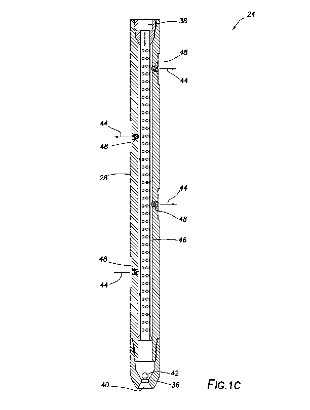
An example well tool assembly 24 is representatively illustrated in FIGS.
1A-C. In a fracturing operation example method, an abrasive perforator 28 cuts
perforations through casing at a certain formation zone. Next, treatment
fluids are
pumped through the perforations, and into the formation zone, thereby
fracturing
the zone.
Note that, in a treatment stage, one or more formation zones may be
perforated and treated. For simplicity and clarity, the description herein
will
assume that a single formation zone is perforated and treated in each stage,
but
CA 03078389 2020-04-02
WO 2019/099600
PCT/US2018/061169
- 4 -
it should be clearly understood that in other examples multiple zones may be
perforated and treated in a single stage. In addition, in the specific
examples
described herein, the treatment comprises fracturing, but in other examples
the
treatment could also, or alternatively, comprise acidizing or another
treatment
technique.
At or near an end of the fracturing, new perforations can be cut with the
abrasive perforator 28. After the perforations are cut, perforation plugs are
pumped down the coiled tubing (or other type of tubular string 34) and out a
discharge port 40 of the perforator 28 to plug up the previous perforations.
The
discharge port 40 is opened by a manipulation of flow rate, pressure, or by
the
effect of a ball, dart or other plugging device 42 on the discharge port.
FIGS. 1A-C shows an example well tool assembly 24 that can be used to
perforate and to deploy perforation plugs. A restriction 36 at a lower end of
the
perforator 28 can be blocked by a ball or other plugging device 42, which
allows
.. the perforator to abrasively perforate, for example, at around 2500 to 3000
psi
(-13.8 to 20.7 MPa) differential pressure applied from an interior
longitudinal flow
passage 38 to an exterior of the well tool assembly 24.
After perforating, the pressure differential can increased to a
predetermined higher pressure differential by increasing a flow rate of fluid
44
through the flow passage 38. This increased differential pressure across the
plugging device 42 forces the plugging device through the restriction 36,
leaving
the discharge port 40 open for deployment of perforation plugs.
A tubular screen 46 is used in the FIGS. 1A-C example to prevent the
perforation plugs from blocking or sticking to nozzles 48 of the perforator
28.
Another plugging device 42 can be pumped down to the restriction 36 (e.g.,
from
surface via the tubular string 34 and flow passage 38) when it is desired to
reactivate the perforator 28. The restriction 36 can be a rigid reduced inner
diameter that permits a plugging device 42 to extrude through at a
predetermined
pressure differential from the flow passage 38 to the exterior of the well
tool
assembly 24.
CA 03078389 2020-04-02
WO 2019/099600 PCT/US2018/061169
- 5 -
Another example restriction 36 is representatively illustrated in FIG. 1D. In
this example, the restriction 36 comprises an expandable tube or ball seat
that
the plugging device 42 can be pumped though at the predetermined pressure
differential.
Instead of extruding or otherwise deforming the plugging device 42, the
expandable restriction 36 enlarges sufficiently at the predetermined pressure
differential to allow the plugging device 42 to pass through the restriction.
The
restriction 36 may, for example, be made of an elastomeric material or another
deformable material or structure that can be sealingly engaged by the plugging
device 42 and enlarged in response to application of the predetermined
differential pressure across the plugging device.
Another example of the well tool assembly 24 is representatively illustrated
in FIGS. 2A-G. In this example, the well tool assembly 24 includes a valve
assembly 30. This discharge port 40 is opened and closed by operation of the
valve assembly 30.
The valve assembly 30 may be the same as or similar to that described in
US Patent No. 9494014, the entire disclosure of which is incorporated herein
by
this reference for all purposes. The valve assembly 30 is operated by
manipulation of the flow rate of the fluid 44 through the flow passage 38 to
displace a piston 52 down (as viewed in FIGS. 2C-D) and thereby open the
discharge port 40.
A J-slot mechanism 54 is used to hold the port 40 open. The port 40 is
closed by applying a subsequent increased flow rate that shifts the J-slot
mechanism 54 to a different position that permits the port 40 to be closed by
a
biasing force exerted by a spring 56.
Thus, the discharge port 40 is alternately opened and closed in response
to a series of flow rate manipulations. The specific pattern of flow rate
manipulations is determined by a cam profile of the J-slot mechanism 54. In
this
example, the discharge port 40 is alternately open and closed when the flow
rate
is decreased following a flow rate increase to at least a predetermined level.
The
CA 03078389 2020-04-02
WO 2019/099600 PCT/US2018/061169
- 6 -
discharge port 40 is open when the flow rate is at or greater than the
predetermined level.
Selectively fired tubing conveyed explosive type perforators may be used
in place of the abrasive jet perforator 28, although there may be practical
limitations on the maximum number of stages possible.
The perforation plugs discharged from the flow passage 38 via the
discharge port 40 may be any type of ball sealers, "frac" balls, diverters,
plugging
devices or substances capable of blocking flow from the wellbore (e.g., the
interior of the casing 16) into a perforated formation zone. Examples of
suitable
plugging devices are described in US Publication No. 2017/0292343, the entire
disclosure of which is incorporated herein by this reference for all purposes.
However, the scope of this disclosure is not limited to use of any particular
type of
perforation plugs.
A perforation plug could seal off a perforation by sealingly engaging a
body of the perforation plug with the perforation, thereby physically blocking
flow
through the perforation itself. In other examples, the perforation plug could
comprise a particulate matter or other substance that enters the perforation
and
blocks fluid flow from the perforation into the formation zone (e.g., the
substance
could form a flow blocking layer or coating on the formation zone in the
perforation, or the substance could enter the formation zone and thereby
substantially decrease its permeability). The scope of this disclosure is not
limited
to any particular mechanism or technique by which the perforation plugs block
flow from the wellbore to the formation zone via the perforations.
The perforation plug could be degradable in the well due to any of a
variety of different stimulants (e.g., passage of time, elevated temperature,
exposure to well fluid, exposure to a particular degrading fluid or substance,
exposure to radiation, etc.). If the perforation plug is degradable, it may be
self-
degrading or degradable in response to a particular action taken (such as,
spotting an acid in the wellbore proximate the perforation plug).
CA 03078389 2020-04-02
WO 2019/099600 PCT/US2018/061169
- 7 -
One significant feature of the example method described above is that
between-stage nonproductive time is substantially eliminated. Another
significant
feature is the capability to recover from a sand off condition by pumping
though
the perforator 28. The elimination of the pad will greatly reduce the time and
amount of fluid required to fracture the well.
One example method (see FIGS. 3-5) for use with a multi-zone well
treatment system 10 includes the steps of:
1. Perforating a first formation zone 14a using a perforator 28 to form
perforations 20a extending through casing 16 and cement 18 lining a wellbore
12. A ball, dart or other plugging device 42 can close off a lower end of an
abrasive perforator 28 by engaging a restriction 36 or expandable seat as
depicted in FIGS. 1C & 1D. In this example, the abrasive perforator 28 forms
the
perforations 20a by directing a fluid jet comprising abrasive particles toward
the
casing 16.
2. Treating the first zone 14a. In this example, the treating includes
forming fractures 26a in the zone 14a by pumping fluid 22 (which may comprise
a
slurry including proppant, water, acid, gel and/or other treatment substances)
from the surface through an annulus 58 formed between the casing 16 and the
tubular string 34 (such as a segmented or continuous tubing string). The
tubular
string 34 is connected to the well tool assembly 24, which in this example
includes the perforator 28 and the valve assembly 30 (see FIGS. 2A-G).
3. Discharging the perforation plugs 60 from the tubular string 34. In this
example, the perforation plugs 60 are pumped downhole via the tubular string
34,
and are discharged from the valve assembly 30. The valve assembly 30 can be
operated as described above (e.g., by manipulating a flow rate through the
valve
assembly) to open its discharge port 40. If, however, the FIGS. 1A-C well tool
assembly is used, the ball or other plugging device 42 can be discharged from
the lower end of the perforator 28, and the perforation plugs 60 can be pumped
through the discharge port 40 into the casing 16. The perforation plugs 60 can
be
discharged from the well tool assembly 24 while the treatment fluid 22 is
being
flowed, for example, at or near a conclusion of step 2 above. The perforation
CA 03078389 2020-04-02
WO 2019/099600 PCT/US2018/061169
- 8 -
plugs 60 block flow through the perforations 20a into the formation zone 14a
(see
FIG. 4).
4. Displacing the well tool assembly 24 to another location in the wellbore
12, so that the perforator 28 is aligned with a next formation zone 14b (see
FIG.
5). The well tool assembly 24 may be displaced during or after the perforation
plugs 60 are discharged from the discharge port 40. The well tool assembly 24
may be displaced during or after the treatment fluid 22 is being flowed into
the
zone 14a.
5. Perforating the second formation zone 14b using the perforator 28 to
form perforations 20b extending through the casing 16 and cement 18, and into
the zone. A ball, dart or other plugging device 42 can close off a lower end
of the
abrasive perforator 28 by engaging a restriction 36 or expandable seat as
depicted in FIG. 1C or 1D. The plugging device 42 may be installed or dropped
during or after either of steps 4 & 5.
Step 2 can be repeated for the second zone 14b (for example, to form
fractures 26b in the second zone), and step 3 can be repeated if one or more
additional zones are to be perforated and treated. Steps 1-4 can be performed
for
each zone or stage to be perforated and treated, except that steps 3 and 4
would
not be performed for the last zone or stage.
In the well treatment system 10 and associated method, the perforation
plugs 60 are discharged from a well tool assembly 24 comprising a perforator
28.
The well tool assembly 24 may also comprise a valve assembly 30 for
discharging the perforation plugs 60 from the well tool assembly. The well
tool
assembly 24 may operate to selectively open and close the discharge port 40 in
response to manipulations of the flow rate (and corresponding pressure
differentials between the flow passage 38 and the annulus 58 or exterior of
the
valve assembly) of the fluid 44 through the flow passage.
The well tool assembly 24 may comprise a restriction 36 (e.g., an
expandable plug seat as depicted in FIG. 1D) for releasably retaining a
plugging
device 42 that blocks flow through the flow passage 38 downstream of the
CA 03078389 2020-04-02
WO 2019/099600 PCT/US2018/061169
- 9 -
perforator 28. The plugging device 42 may be installed in the well tool
assembly
24 prior to perforating a formation zone 14a or 14b. The plugging device 42
may
be discharged from the well tool assembly 24 prior to discharging the
perforation
plugs 60 from the well tool assembly 24.
Referring additionally now to FIG. 6 a representative flowchart for another
example of the method 70 for perforating and treating multiple formation zones
in
a well is depicted. The FIG. 6 method 70 may be practiced using the system 10
and well tool assembly 24 examples described above, or another system or well
tool assembly may be used with the method. In the further description below,
the
system 10 and well tool assembly 24 is used in the method 70.
In step 72, the well tool assembly 24 is run into the wellbore 12 and is
positioned so that the perforator 28 is aligned with the zone 14a. In this
example,
the well tool assembly 24 is conveyed on the tubular string 34, which may
comprise a continuous tubing string (e.g., coiled tubing) or a segmented
tubing
string.
In step 74, the discharge port 40 is closed. The plugging device 42 may be
deployed into the well tool assembly 24, so that it sealingly engages the
restriction 36 and thereby prevents flow through the flow passage 38
downstream
of the perforator 28. If the FIG. 2A-G well tool assembly 24 is used, a flow
rate of
the fluid 44 through the flow passage 38 may be manipulated, so that the
discharge port 40 is closed (if the discharge port is not already closed). In
either
case, the discharge port 40 may be closed prior to or after the well tool
assembly
24 is run into the well or positioned as described above for step 72.
In step 76, the zone 14a is perforated by the perforator 28. In this
example, the fluid 44 comprising abrasive particles is flowed through the flow
passage 38 and out of the nozzles 48, so that it impinges on the casing 16 and
eventually forms the perforations 20a through the casing and cement 18, and
into
the zone 14a. In other examples, an explosive, mechanical, chemical or other
type of perforator may be used in the well tool assembly 24 to form the
perforations 20a.
CA 03078389 2020-04-02
WO 2019/099600 PCT/US2018/061169
- 10 -
In step 78, the zone 14a is treated by flowing the treatment fluid 22 from
the surface and through the annulus 58 to the open perforations 20a. The
treatment fluid 22 flows through the perforations 20a and into the zone 14a,
for
example, to form the fractures 26a. It is not necessary, however, for
fractures to
be formed in the zone 14a during this treatment step.
In step 80, the discharge port 40 is opened. In the FIGS. 1A-C example of
the well tool assembly 24, the discharge port 40 can be opened by increasing
the
pressure differential from the flow passage 38 to the exterior of the well
tool
assembly (e.g., across the plugging device 42), thereby deforming the plugging
device so that it passes through (e.g., is extruded through) the restriction
36.
In the FIG. 1D example, the discharge port 40 can be opened by
increasing the pressure differential from the flow passage 38 to the exterior
of the
well tool assembly (e.g., across the plugging device 42), thereby deforming
the
restriction 36 (e.g., expanding or otherwise enlarging the restriction) so
that the
plugging device can pass through the restriction.
In the FIGS. 2A-G example, the discharge port 40 can be opened by
manipulating the flow rate of the fluid 44 through the passage 38 to thereby
manipulate the pressure differential from the passage to the exterior of the
well
tool assembly 24.
Note that the discharge port 40 can be opened in the step 80 prior to or
after conclusion of the treatment step 78. In this manner, discharge of the
perforation plugs 60 from the well tool assembly 24 can begin prior to or
after
conclusion of the treatment step 78, so that unproductive time between these
steps is eliminated, or at least minimized or substantially reduced.
In step 82, the perforations 20a are plugged by discharging the perforation
plugs 60 from the well tool assembly 24 via the open discharge port 40. As
mentioned above, the perforation plugs 60 may begin to be discharged prior to
conclusion of the treatment step 78, for example, to divert the fluid 22 from
perforations 20a taking most of the fluid to perforations taking less fluid.
Preferably, at a conclusion of the perforation plugging step 82, all of the
CA 03078389 2020-04-02
WO 2019/099600 PCT/US2018/061169
- 11 -
perforations 20a are plugged, so that they will take no further (or minimal)
fluid
during subsequent treatments of additional zones.
In step 84, the well tool assembly 24 is repositioned, so that the perforator
28 is aligned with the next zone 14b to be treated. The well tool assembly 24
may
be repositioned before, during or after the treatment step 78, discharge port
opening step 80 or perforation plugging step 82. Thus, the well tool assembly
24
may be repositioned at any time after the zone 14a perforating step 76, and
before the zone 14b perforating step 88 described below.
In step 86, the discharge port 40 is closed. Closing of the discharge port
40 permits the perforator 28 to be used to form the perforations 20b into the
zone
14b. In the FIGS. 1A-D examples, the discharge port 40 may be closed by
deploying another plugging device 42 into the flow passage 38, so that it will
sealingly engage the restriction 36.
In the FIGS. 2A-G example, the discharge port 40 may be closed by
manipulating the flow rate of the fluid 44 through the flow passage 38,
thereby
manipulating the pressure differential from the flow passage to the exterior
of the
well tool assembly 24. Note that, when the discharge port 40 is closed, a
valve 50
(see FIG. 2F) that selectively permits and prevents flow through the passage
38
is opened, thereby permitting flow of the fluid 44 to the perforator 28. The
valve
50 is closed when the discharge port 40 is open, in this example.
In step 88, the zone 14b is perforated by the perforator 28. In this
example, the fluid 44 comprising abrasive particles is flowed through the flow
passage 38 and out of the nozzles 48, so that it impinges on the casing 16 and
eventually forms the perforations 20b through the casing and cement 18, and
into
the zone 14b. In other examples, an explosive, mechanical, chemical or other
type of perforator may be used in the well tool assembly 24 to form the
perforations 20b.
In step 90, the zone 14b is treated by flowing the treatment fluid 22 from
the surface and through the annulus 58 to the open perforations 20b. The
treatment fluid 22 flows through the perforations 20b and into the zone 14b,
for
CA 03078389 2020-04-02
WO 2019/099600 PCT/US2018/061169
- 12 -
example, to form the fractures 26b. It is not necessary, however, for
fractures to
be formed in the zone 14b during this treatment step.
If additional zones are to be perforated and treated, steps 80-90 may be
repeated for each additional zone. It will be appreciated that any number of
zones may be perforated and treated using the method 70, with only a single
trip
of the well tool assembly 24 into the well.
Referring again to the well tool assembly 24 example of FIGS. 1A-D, it
may be seen that this example includes a tubing connector 32, back pressure
valves 62 and a hydraulic release tool 64 connected between the tubular string
34 and the perforator 28. A suitable tubing connector for use as the tubing
connector 32 in the well tool assembly 24 is the External Slip Type Coiled
Tubing
Connector marketed by Thru Tubing Solutions, Inc. of Oklahoma City, Oklahoma
USA. A suitable back pressure valve assembly for use as the back pressure
valves 62 is the Dual Flapper Back Pressure Valve marketed by Thru Tubing
Solutions, Inc. A suitable hydraulic release tool for use as the hydraulic
release
tool 64 is the Hydraulic Disconnect marketed by Thru Tubing Solutions, Inc.
Additional, fewer or different well tools may be used in the FIGSD. 1A-D well
tool
assembly 24, in keeping with the principles of this disclosure.
Referring additionally to the well tool assembly 24 example of FIGS. 2A-G,
it may be seen that this example includes the tubing connector 32, the back
pressure valves 62, the hydraulic release tool 64 and the valve assembly 30
connected between the tubular string 34 and the perforator 28. A suitable
valve
assembly for use as the valve assembly 30 in the well tool assembly 24 is that
described in US Patent No. 9494014. Additional, fewer or different well tools
may
be used in the FIGS. 2A-G well tool assembly 24, in keeping with the
principles of
this disclosure.
A downhole well tool assembly 24 described herein can comprise a
perforator 28 and a selectively openable and closable perforation plug
discharge
port 40.
CA 03078389 2020-04-02
WO 2019/099600
PCT/US2018/061169
- 13 -
In any of the examples described herein, the downhole well tool assembly
24 can comprise a valve assembly 30 configured to selectively open and close
the perforation plug discharge port 40 in response to manipulation of a fluid
flow
rate through a longitudinal flow passage 38 extending through the valve
assembly 30.
In any of the examples described herein, the flow passage 38 may extend
longitudinally through the perforator 28.
In any of the examples described herein, the valve assembly 24 can
comprise a valve 50 that opens and permits fluid flow through the flow passage
38 to the perforator 28 when the perforation plug discharge port 40 is closed.
In any of the examples described herein, the valve 50 may close and
prevent fluid flow through the flow passage 38 to the perforator 28 when the
perforation plug discharge port 40 is open.
In any of the examples described herein, sealing engagement between a
plugging device 42 and a restriction 36 in a flow passage 38 extending
longitudinally through the perforator 28 may block flow through the
perforation
plug discharge port 40.
In any of the examples described herein, the plugging device 42 may be
configured to deform and pass through the restriction 36 in response to a
predetermined pressure differential applied from the flow passage 38 to an
exterior of the downhole well tool assembly 24.
In any of the examples described herein, the restriction 36 may be
configured to enlarge and permit the plugging device 42 to pass through the
restriction 36 in response to a predetermined pressure differential applied
from
the flow passage 38 to an exterior of the downhole well tool assembly 24.
In any of the examples described herein, the perforation plug discharge
port 40 may be positioned downstream of the perforator 28 relative to fluid
flow
through the flow passage 38.
CA 03078389 2020-04-02
WO 2019/099600 PCT/US2018/061169
- 14 -
In any of the examples described herein, fluid flow may be permitted
through the perforation plug discharge port 40 and nozzles 48 of the
perforator
28 simultaneously when the plugging device 42 is not sealingly engaged with
the
restriction 36.
A method 70 of perforating and treating multiple formation zones 14a,b of
a well in a single trip of a downhole well tool assembly 24 into the well is
described herein. In one example, the method 70 can comprise:
(a) positioning the downhole well tool assembly 24 at a first zone 14a;
(b) closing a perforation plug discharge port 40 of the downhole well tool
assembly 24;
(c) perforating the first zone 14a;
(d) treating the first zone 14a;
(e) opening the perforation plug discharge port 40;
(f) deploying perforation plugs 60 into the well via the perforation plug
discharge port 40;
(g) plugging perforations 20a in the first zone 14a with the perforation
plugs 60;
(h) positioning the downhole well tool assembly 24 at a second zone 14b;
(i) closing the perforation plug discharge port 40;
(j) perforating the second zone 14b; and
(k) treating the second zone 14b.
In any of the examples described herein, the step of closing the perforation
plug discharge port 40 may be performed prior to the step of positioning the
downhole well tool assembly 24 at the first zone 14a.
In any of the examples described herein, the step of closing the perforation
plug discharge port 40 may be performed after the step of positioning the
downhole well tool assembly 24 at the first zone 14a.
CA 03078389 2020-04-02
WO 2019/099600 PCT/US2018/061169
- 15 -
In any of the examples described herein, the step of closing the perforation
plug discharge port 40 may be performed during the step of positioning the
downhole well tool assembly 24 at the first zone 14a.
In any of the examples described herein, the step of opening the
perforation plug discharge port 40 may be performed prior to the step of
treating
the first zone 14a.
In any of the examples described herein, the step of opening the
perforation plug discharge port 40 may be performed after the step of treating
the
first zone 14a.
In any of the examples described herein, the step of opening the
perforation plug discharge port 40 may be performed during the step of
treating
the first zone 14a.
In any of the examples described herein, the step of opening the
perforation plug discharge port 40 may comprise increasing a pressure
differential from an interior to an exterior of the downhole well tool
assembly 24.
In any of the examples described herein, the step of increasing the
pressure differential may comprise deforming a plugging device 42 through a
restriction 36 in a flow passage 38 extending longitudinally through a
perforator
28.
In any of the examples described herein, increasing the pressure
differential may comprise deforming a restriction 36 in a flow passage 38
extending longitudinally through a perforator 28, thereby permitting a
plugging
device 42 to pass through the restriction 36.
In any of the examples described herein, increasing the pressure
differential may comprise increasing a flow rate through a flow passage 38
extending longitudinally through the downhole well tool assembly 24.
In any of the examples described herein, the flow passage 38 may extend
longitudinally through a perforator 28 of the downhole well tool assembly 24.
CA 03078389 2020-04-02
WO 2019/099600
PCT/US2018/061169
- 16 -
In any of the examples described herein, increasing the pressure
differential may further comprise closing a valve 50 of the downhole well tool
assembly 24, thereby preventing fluid flow to a perforator 28 of the downhole
well
tool assembly 24.
In any of the examples described herein, the method may further
comprise, after step (k):
(I) opening the perforation plug discharge port 40;
(m) deploying perforation plugs 60 into the well via the perforation plug
discharge port 40;
(n) plugging perforations 20b in the second zone 14b with the perforation
plugs 60;
(o) positioning the downhole well tool assembly 24 at a third zone;
(p) closing the perforation plug discharge port 40;
(q) perforating the third zone; and
(r) treating the third zone.
Another method of perforating and treating multiple formation zones 14a,b
of a well in a single trip of a downhole well tool assembly 24 into the well
is
described herein. In one example, the method can comprise:
(a) perforating a first zone 14a with an abrasive perforator 28 of a
downhole well tool assembly 24;
(b) treating the first zone 14a by flowing a treatment fluid 22 through an
annulus 58 formed between the downhole well tool assembly 24 and a casing 16
of the well;
(c) discharging perforation plugs 60 from the downhole well tool assembly
24, thereby plugging perforations 20a of the first zone 14a;
(d) positioning the downhole well tool assembly 24 at a second zone 14b;
(e) perforating the second zone 14b with the abrasive perforator 28; and
CA 03078389 2020-04-02
WO 2019/099600
PCT/US2018/061169
- 17 -
(f) treating the second zone 14b by flowing the treatment fluid 22 through
the annulus 58.
In any of the examples described herein, step (c) may be commenced
prior to conclusion of step (b).
In any of the examples described herein, step (d) may be commenced
prior to conclusion of step (b).
In any of the examples described herein, step (d) may be commenced
prior to conclusion of step (c).
In any of the examples described herein, the step of discharging the
perforation plugs 60 may comprise displacing the perforation plugs 60 through
the abrasive perforator 28.
In any of the examples described herein, the step of discharging the
perforation plugs 60 may comprise displacing the perforation plugs 60 through
a
flow passage 38 extending longitudinally through the abrasive perforator 28.
In any of the examples described herein, the step of discharging the
perforation plugs 60 may comprise displacing a plugging device 42 through a
restriction 36 in a flow passage 38 extending longitudinally through the
downhole
well tool assembly 24.
In any of the examples described herein, the step of displacing the
plugging device 42 through the restriction 36 may comprise deforming the
plugging device 42.
In any of the examples described herein, the step of displacing the
plugging device 42 through the restriction 36 may comprise deforming the
restriction 36.
In any of the examples described herein, the step of discharging the
perforation plugs 60 may comprise manipulating a fluid flow rate through the
downhole well tool assembly 24, thereby opening a perforation plug discharge
port 40 of the downhole well tool assembly 24.
CA 03078389 2020-04-02
WO 2019/099600 PCT/US2018/061169
- 18 -
Although various examples have been described above, with each
example having certain features, it should be understood that it is not
necessary
for a particular feature of one example to be used exclusively with that
example.
Instead, any of the features described above and/or depicted in the drawings
can
be combined with any of the examples, in addition to or in substitution for
any of
the other features of those examples. One example's features are not mutually
exclusive to another example's features. Instead, the scope of this disclosure
encompasses any combination of any of the features.
Although each example described above includes a certain combination of
features, it should be understood that it is not necessary for all features of
an
example to be used. Instead, any of the features described above can be used,
without any other particular feature or features also being used.
It should be understood that the various embodiments described herein
may be utilized in various orientations, such as inclined, inverted,
horizontal,
vertical, etc., and in various configurations, without departing from the
principles
of this disclosure. The embodiments are described merely as examples of useful
applications of the principles of the disclosure, which is not limited to any
specific
details of these embodiments.
In the above description of the representative examples, directional terms
(such as "above," "below," "upper," "lower," "upward," "downward," etc.) are
used
for convenience in referring to the accompanying drawings. However, it should
be
clearly understood that the scope of this disclosure is not limited to any
particular
directions described herein.
The terms "including," "includes," "comprising," "comprises," and similar
terms are used in a non-limiting sense in this specification. For example, if
a
system, method, apparatus, device, etc., is described as "including" a certain
feature or element, the system, method, apparatus, device, etc., can include
that
feature or element, and can also include other features or elements.
Similarly, the
term "comprises" is considered to mean "comprises, but is not limited to."
CA 03078389 2020-04-02
WO 2019/099600
PCT/US2018/061169
- 19 -
Of course, a person skilled in the art would, upon a careful consideration
of the above description of representative embodiments of the disclosure,
readily
appreciate that many modifications, additions, substitutions, deletions, and
other
changes may be made to the specific embodiments, and such changes are
contemplated by the principles of this disclosure. For example, structures
disclosed as being separately formed can, in other examples, be integrally
formed and vice versa. Accordingly, the foregoing detailed description is to
be
clearly understood as being given by way of illustration and example only, the
spirit and scope of the invention being limited solely by the appended claims
and
their equivalents.