Note: Descriptions are shown in the official language in which they were submitted.
CA 03078580 2020-04-06
WO 2019/069291 PCT/IB2018/057765
1
Reinforced Sheath for a Steerable Sheath Assembly
TECHNICAL FIELD
[0001] The disclosure relates to a reinforced sheath for a steerable
sheath assembly. More specifically, the present disclosure relates to a
steerable sheath assembly that provides a reinforced sheath at the point
of contact of the pull wires to the sheath.
BRIEF DESCRIPTION OF THE DRAWINGS
[0002] In order that the invention may be readily understood,
embodiments of the invention are illustrated by way of examples in the
accompanying drawings, in which:
[0003] Fig. 1A-1F are an illustration of a steerable sheath assembly in
accordance with various embodiments of the present invention;
[0004] Figs. 2A-2D are an illustration of a steerable sheath assembly
in
accordance with various alternate embodiments of the present invention;
[0005] Fig. 3A is an illustration of a pull-ring/ pull wire assembly
with a
mechanical lock; and
[0006] Fig. 3B is an illustration of multiple anchor holes on a pull-
ring.
DETAILED DESCRIPTION
[0007] Some medical procedures may require the use of a steerable
sheath or catheter in order to reach a desired location within a patient's
body in order to treat the patient. The steerable sheath or catheter may
be deflectable upon actuation of a steerable sheath or catheter control
handle. Some such steerable catheter control handles comprise
CA 03078580 2020-04-06
WO 2019/069291 PCT/IB2018/057765
2
actuation mechanisms that are actuable to deflect the sheath by
actuating of one or more control or pull wires that are coupled to the
sheath. In some such examples, the one or more pull wires may be
coupled to the sheath along a distal segment of the sheath, allowing the
actuator to deflect a distal portion of the sheath at the desired curvature.
[0008] However, some such steerable sheaths may not be able to
withstand a high degree of deflection of the sheath, and/or repeated
actuation of the sheath without failure. In some such examples, high
degree of deflection of the steerable sheath and/or repeated deflections
of the steerable sheath may result in failure of the steerable sheath at the
point of contact of the pull wires with the sheath. Furthermore, such
sheaths may not be able to perform adequately without failure when one
or more devices are used in conjunction with the steerable sheath and
the steerable sheath is used to curve the assembly. In some such
examples, the steerable sheath may be used with a needle and/or a
dilator positioned within the steerable sheath, and the steerable sheath
may be curved. Some such prior art systems may observe failure at the
pull wire connection at the sheath, due to the stress or strain put on the
sheath from curving the one or more rigid devices along with it due to
higher forces and greater actuation required to deflect the sheath.
[0009] The inventors of the present invention have discovered a unique
problem associated with prior art steerable sheath assemblies that result in
failure at the point of contact between the pull wires and the sheath and
presented a novel solution to solve the same. The present inventors have
discovered that in prior systems the failure at the point of contact
CA 03078580 2020-04-06
WO 2019/069291 PCT/IB2018/057765
3
between the pull wires and the sheath is a result of the weakness in the
portion of the shaft of the sheath where the pull wires are connected.
[0010] In some embodiments of systems that use pull rings to connect
the pull wires to the sheath, the present inventors have discovered that
there is weakness in the segment of the shaft at the point/interface where
the pull wires are connected to the sheath, via the pull ring. The present
inventors have additionally discovered that the weakness may result in
displacement and or pivoting of the pull-wire out of position about the
point of attachment of the pull ring to the sheath such as the pull-ring
anchor hole, upon deflection of the steerable sheath. As such the
weakness in the shaft may result in displacement of the coupling between
the pull wires and the shaft. In some cases the pull ring may be able to
pivot or displace proximally behind a deflectable section of the sheath
that may be immediately proximal to the coupling [such as a pull ring]. In
some such situations, as the pull wires are deflected, the angle between
the pull wire and the coupling [such as pull-ring] may become greater
than 90 degrees due to weakness in the shaft resulting in curvature at the
joint between the pull-wires and the pull-ring which may be a weld-joint,
which may result in breaking of the weld-joint due to breakage.
[0011] In some embodiments, the coupling [such as a pull-ring] may be
able to pivot at the pull-ring anchor hole which is a hole through which
the polymer layers of shaft of the sheath through flow to form a peg to
keep the pull-ring in place, once the pull wires are deflected, resulting in
rotational displacement of the pull-ring.
[0012] As will be presently described, the present inventors have
additionally discovered a unique solution to solving the problem by
CA 03078580 2020-04-06
WO 2019/069291 PCT/IB2018/057765
4
providing a means for preventing displacement of the coupling. The
present inventors have discovered and invented embodiments for
reinforcing the area of the shaft of the steerable sheath where the pull
wires are coupled, to help minimize failure at the interface between the
pull wires and sheath.
[0013] In systems where a pull ring is used to couple one or more pull
wires to the shaft of the steerable sheath, present inventors have
discovered unique solutions to reinforce an area of the steerable sheath
shaft where the pull ring is located.
[0014] In one broad aspect, embodiments of the present invention
comprise a reinforced steerable sheath assembly that is usable with an
actuator comprising: a shaft section defining a sheath that is operable to
be deflected, and one or more pull wires that are coupled to the sheath
via a coupling at a point of contact between the pull wires and the
sheath. The pull wires are operable to be coupled to the actuator for
actuating the pull wires. The reinforced steerable sheath assembly further
comprises a means for preventing displacement of the coupling, wherein
the means for preventing displacement to minimize failure at the coupling
at the point of contact between the pull wires and the sheath upon
actuation of the pull wires upon actuation of the actuator to deflect the
sheath.
[0015] As a feature of this broad aspect, the means for preventing
displacement of the coupling comprises a reinforcement/reinforced
section for reinforcing the coupling, wherein the reinforcement, defines a
portion of the sheath.
CA 03078580 2020-04-06
WO 2019/069291 PCT/IB2018/057765
[0016] As
example of this feature, the reinforcement/reinforced section
is defined by/comprises a proximal reinforcement/reinforced section that
is positioned behind the coupling to prevent displacement of the
coupling upon actuation of the pull wires.
5 [0017] As a further example of this feature, the reinforcement/reinforced
section is defined by/comprises an
encapsulating
reinforcement/reinforced section that is positioned around/over the
coupling to help prevent proximal displacement and rotational
displacement of the coupling.
[0018] In one instance of this example, the encapsulating
reinforcement/reinforced section is formed integrally with the proximal
reinforcement/reinforced section.
[0019] In some embodiments of the present invention, the
reinforcement/reinforced section enables an angle between the pull wire
and the coupling to be maintained substantially at about 90 degrees
during actuation.
[0020] As
an example of this feature, the reinforcement/reinforced
section is defined by/comprises an encapsulating reinforcement
/reinforced section that is positioned around/over the coupling to help
prevent proximal displacement and rotational displacement of the
coupling.
[0021] As an example of any one of the examples described herein
above, the coupling comprises a pull-ring.
CA 03078580 2020-04-06
WO 2019/069291 PCT/IB2018/057765
6
[0022] In one such example, the reinforcement/reinforced section is
defined by/ comprises at least two pull ring anchor holes for coupling the
pull ring to the sheath.
[0023] In another example, the reinforcement/reinforced section
comprises an integrated pull-ring that is coupled to one or more
components of the sheath to minimize displacement by providing a
longer fulcrum requiring greater force to displace the pull-ring.
[0024] In a specific instance of this example, the integrated pull-ring
comprises a pull-ring that is coupled to a marker band.
[0025] As another example of this feature, the reinforcement comprises at
least two connections/points of contact for connecting the coupling to
the sheath.
[0026] As still another example of this feature, the
reinforcement/reinforced section comprises an integrated coupling that is
connected to one or more components of the sheath to minimize
displacement by providing a longer fulcrum requiring greater force to
displace the coupling.
[0027] In one such example, the integrated coupling comprises a coupling
that is connected to a marker band.
[0028] As still another example of this
feature, the
reinforcement/reinforced section comprises a polymer under layer, to
enable the coupling to be captured substantially between the polymer
under layer and a polymer over layer defining a portion of the shaft to be
surrounded thereby.
CA 03078580 2020-04-06
WO 2019/069291 PCT/IB2018/057765
7
[0029] In a further broad aspect, embodiments of the present invention
comprise a reinforced steerable sheath assembly that is usable with an
actuator comprising, a shaft section defining a sheath that is operable to
be deflected, and one or more pull wires that are coupled to the sheath
via a coupling at a point of contact between the pull wires and the
sheath. The pull wires being operable to be coupled to the actuator for
actuating the pull wires. The reinforced steerable sheath assembly further
comprises a reinforcement/reinforced section for reinforcing the coupling,
the reinforcement/reinforced section defining a portion of the sheath,
wherein the reinforcement/reinforced section prevents displacement of
the coupling to help minimize failure at the coupling upon actuation of
the actuator to actuate the pull wires to deflect the sheath.
[0030] In a further broad aspect, embodiments of the present invention
comprise a reinforced steerable sheath assembly that is usable with an
actuator comprising, a shaft section defining a sheath that is operable to
be deflected. The shaft section has a proximal end and a distal end and
the actuator is positioned proximate the proximal end of the shaft section.
The reinforced steerable sheath assembly further comprises a coupling
attached proximate the distal end of the shaft section, and one or more
pull wires. A distal end of the pull wires are coupled proximate the distal
end of the shaft section via the coupling, and the proximal end of the pull
wires being coupled to the actuator for actuating the pull wires. The
reinforced steerable sheath assembly further comprises a means for
preventing displacement of the coupling positioned proximate to the
coupling, whereby said means helps to minimize failure of the coupling at
a point of contact between the pull wires and the coupling, and at a
CA 03078580 2020-04-06
WO 2019/069291 PCT/IB2018/057765
8
point of contact between the coupling and the sheath, upon actuation
of the pull wires to deflect the sheath.
[0031] As a feature to this broad aspect, the means for preventing
displacement of the coupling comprises a reinforced section for
reinforcing the coupling.
[0032] As example of this feature, the reinforced section comprises a
proximal reinforcement member positioned proximal to the coupling to
prevent displacement of the coupling upon actuation of the pull wires.
[0033] In one such example, the reinforcement member supports the
coupling to prevent displacement.
[0034] As a further example of this feature, the reinforced section
comprises an encapsulating member that is positioned over the coupling
to prevent proximal displacement and rotational displacement of the
coupling upon actuation of the pull wires.
[0035] In one such example, the reinforced section further comprises a
proximal reinforcement member positioned proximal to the coupling.
[0036] As a further example of the feature, the the encapsulating member
is integral with the proximal reinforcement member.
[0037] As an example of any one of the examples described herein
above, the coupling comprises a pull-ring.
[0038] As example of this feature, the reinforced section comprises at least
two pull ring anchor holes for coupling the pull ring to the shaft section.
CA 03078580 2020-04-06
WO 2019/069291 PCT/IB2018/057765
9
[0039] Another example of this feature, the reinforced section comprises
an integrated pull-ring that is coupled to one or more components of the
sheath to minimize displacement by providing a longer fulcrum requiring
greater force to displace the pull-ring.
[0040] In a specific instance, the integrated pull-ring comprises the pull-
ring
coupled to a marker band.
[0041] As a feature to this broad aspect, the reinforced section comprises
at least two points of contact for connecting the coupling to the shaft
section.
[0042] As another feature to the broad aspect, the reinforced section
comprises an integrated coupling that is connected to one or more
components of the sheath to minimize displacement by providing a
longer fulcrum requiring greater force to displace the coupling.
[0043] As a further example of this feature, the integrated coupling
comprises the coupling connected to a marker band.
[0044] As another feature of the broad aspect, the reinforced section
comprises a polymer under layer, to enable the coupling to be captured
substantially between the polymer under layer and a polymer over layer
defining a portion of the shaft to be surrounded thereby.
[0045] As an example of any one of the examples described herein
above, the reinforced steerable sheath further comprising a locking
member, wherein the at least one pull wire is attached at the distal end of
the at least one pull wire to the locking member. The locking member is
dimensioned to fixably couple to a corresponding aperture on the
CA 03078580 2020-04-06
WO 2019/069291 PCT/IB2018/057765
coupling, whereby when the locking member and aperture are coupled,
the pull wires are fixed relative to the coupling.
[0046] In a specific instance, the locking member comprises a rectangular
member and the aperture is a rectangular slot.
5 [0047] As an example of any one of the examples described herein
above, the reinforced section is a substantially rigid polymer.
[0048] In a specific instance, the substantially rigid polymer comprises 72D
Pebax or Nylon 12.
[0049] In some embodiment of the present invention, the reinforced
10 section substantially maintains an angle between the pull wire and the
coupling to be about 90 degrees during actuation.
[0050] In some embodiment of the present invention, the section
substantially proximal to the coupling is straight.
[0051] In a further broad aspect, a reinforced steerable sheath assembly
comprising, a shaft section defining a sheath that is operable to be
deflected, the shaft section having a proximal end and a distal end, and
an actuator positioned proximate the proximal end of the shaft section.
The reinforced steerable sheath assembly further comprises a coupling
attached proximate the distal end of the shaft section, and one or more
pull wires. A distal end of the pull wires are coupled proximate the distal
end of the shaft section via the coupling and wherein a proximal end of
the pull wires are coupled to the actuator. The steerable sheath assembly
further comprises a reinforced section positioned proximate to the
CA 03078580 2020-04-06
WO 2019/069291 PCT/IB2018/057765
11
coupling, wherein the reinforced section prevents displacement of the
coupling upon actuation of the pull wires to deflect the sheath.
[0052] With specific reference now to the drawings in detail, it is stressed
that the particulars shown are by way of example and for purposes of
illustrative discussion of certain embodiments of the present invention only.
Before explaining at least one embodiment of the invention in detail, it is
to be understood that the invention is not limited in its application to the
details of construction and the arrangement of the components set forth
in the following description or illustrated in the drawings. The invention is
capable of other embodiments or of being practiced or carried out in
various ways. Also, it is to be understood that the phraseology and
terminology employed herein is for the purpose of description and should
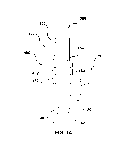
not be regarded as limiting. In one embodiment of the present invention,
as shown in Fig. 1A, a reinforced steerable sheath assembly 300 is
provided that is usable with an actuator. The reinforced steerable sheath
assembly 300 comprises a shaft section 100 that defines a sheath 200 that
is operable to be deflected. The reinforced steerable sheath assembly 300
further comprises one or more pull wires 40, 42 that are coupled to the
sheath 100 via a coupling 400 at a point of contact between the pull
wires 40, 42 and the sheath 200.
[0053] The pull wires 40, 42 are operable to be coupled to an actuator for
actuating the pull wires 40, 42. The reinforced steerable sheath assembly
300 additionally comprises a means 500 for preventing displacement of
the coupling 400. In some such embodiments, the means 500 for
preventing displacement of the coupling comprises a reinforcement
/reinforced section 150 for reinforcing the coupling 400 [for example by
CA 03078580 2020-04-06
WO 2019/069291 PCT/IB2018/057765
12
reinforcing an area of the shaft 100 around the coupling 400], wherein the
reinforcement/ reinforced section 150 defines a portion of the sheath 200.
In the example shown, the means 500 for preventing displacement (a
reinforcement /reinforced section 150) helps to minimize failure at the
coupling 400 at the point of contact between the pull wires 40, 42 and the
sheath 200 (or in other words a portion of the shaft 100 of the sheath 200)
upon actuation of the pull wires upon actuation of the actuator to deflect
the sheath.
[0054] In accordance with the embodiment as shown in Fig. 1A, the
means for preventing displacement of the coupling, such as a
reinforcement/reinforced section 150 prevents both proximal
displacement of the coupling 400 [such as a pull-ring 402] as well as
rotational displacement or pivoting of the coupling [such as the pull-ring
402]. The proximal displacement and rotational displacement or pivoting
is shown with respect to Figs. 1B and 1C showing embodiments of the
present invention, for illustrative purposes only. Proximal displacement
occurs when the coupling 400 displaces proximally towards the proximal
end of the shaft, and in some cases, the displaced coupling interferes with
or is positioned proximally to the deflectable section of the sheath 120. This
.. typically results from failure of the means for attaching the coupling 400
to
the shaft, which is illustrated at item 192 in Fig. 1B. Rotational
displacement
occurs when the coupling 400 pivots and experiences rotational
displacement around an axis (for example, where the coupling 400 is fixed
using a single anchor point, coupling 400 rotationally displaces about the
axis created by that anchor point) and the angle between the coupling
400 and the pull wire 40, 42 is no longer maintained at 90 degrees. The
curvature at the joint between the coupling 400 and the pull wire 40, 42
CA 03078580 2020-04-06
WO 2019/069291 PCT/IB2018/057765
13
may result in breaking of the joint as illustrated at item 194 in Fig. 1C.
Failure may result from a combination of both rotational and proximal
displacement.
Reinforcement/ reinforced section
Proximal reinforcement/reinforced section and encapsulating
reinforcement/reinforced section
[0055] In some embodiments of the present invention, the
reinforcement/reinforced section enables the angle between the pull wire
and the coupling 400 to be maintained substantially at about 90 degrees
during actuation.
[0056] With reference again to Fig. 1A as well in Figs. 1D and 1E, in one
embodiment of the present invention, the reinforcement/reinforced
section 150 is defined by/comprises a proximal reinforcement member
such as proximal reinforcement/reinforced section 152 that is positioned
behind the coupling 400 [such as the pull ring 402] to prevent
displacement of the coupling 400 upon actuation of the pull wires 40, 42.
The proximal reinforcing/reinforced section 152 in some examples
comprises a substantially rigid section, for example comprising polymer,
such as portion of Nylon 12. In some such examples, of steerable sheath
assembly of the present invention, the coupling 400 is positioned distal to
the bendable or deflectable portion of the shaft, which in some examples
comprises a 35D durometer section of Pebax polymer. As such, the
proximal reinforcing/ reinforced section 152 functions as a stop to prevent
rotation of the coupling 400 [such as pull-ring 402], and additionally can
help prevent the coupling 400 [such as pull-ring 402], from slipping
CA 03078580 2020-04-06
WO 2019/069291 PCT/IB2018/057765
14
proximally and/or behind the deflectable section 120 of the sheath 200
[which is now proximal to the reinforcing/ reinforced section 152]. In some
examples the proximal reinforcement/reinforced or reinforcing section 152
may also capture a distal end of a braid of the shaft 100 to capture the
frayed edges therein. Fig. 1F is a cross section of the specific embodiment
of a reinforced sheath 200 seen in Fig 1E along the cut-line BM. The
specific embodiment has two pull wire lumens 44, 46 secured under layer
170 (e.g., a braided wire). The pull wires 40, 42 run through the pull wire
lumens 44, 46 along the length of the shaft 100.
[0057] In some embodiments of the present invention, with reference
again to Figs. 1A, 1D and 1E, the reinforcement/reinforced section 150 is
defined by or comprises an encapsulating member such as an
encapsulating reinforcement/reinforced section 154 that is positioned
around/over the coupling 400 [such as pull-rings 402] to help prevent
proximal displacement and rotational displacement of the coupling. The
reinforcement/reinforced section 154 functions to cap and/or grip the
coupling 400 [such as pull-rings 402] to substantially minimize the
movement or displacement of the pull-ring under deflection of the pull-
wires. In some such embodiments, the encapsulating
reinforcement/reinforced section 150 additionally encapsulates a marker
band 160 that is positioned distal to the pull-ring 402.
[0058] In some such examples, both
encapsulating
reinforcement/reinforced section 154 and the
proximal
reinforcement/reinforced section 152 together help to encapsulate the
coupling 400 [such as pull-ring 402] and keep it straight to mitigate
against failure at the pull wire/pull-ring interface. The reinforcement at the
CA 03078580 2020-04-06
WO 2019/069291 PCT/IB2018/057765
joint which may be a weld joint may help prevent fatigue. In the
embodiment, described herein, the proximal and encapsulating
reinforcements/reinforcement sections 152, 154 may comprise a
substantially rigid polymer. In some such examples, the substantially rigid
5 polymer comprises a 72D Pebax. In other examples, the substantially rigid
polymer comprises Nylon 12.
[0059] In a specific example the encapsulating reinforcement/reinforced
section 154 is formed integrally with the proximal reinforcement/reinforced
section 152. In some such examples, both encapsulating and proximal
10 reinforcement/reinforced sections 154, 152 comprise Nylon 12.
[0060] In some such embodiments, encapsulating reinforcement/
reinforced section 154 provided overtop the coupling 400 [such as pull-
ring 402] functions grip the pull-ring 402 to prevent movement thereof and
the proximal reinforcement/ reinforced section 152 that is the section that
15 is behind the pull ring 402 stops the movement of the pull-ring 402
because of stiffness of the material the defines the proximal
reinforcement/reinforced section 152 such as Nylon 12.
[0061] As the pull wires are actuated, the proximal reinforcement
/reinforced section 152 behind the pull-ring 402 remains substantially
straight as the sheath 200 bends. Both the encapsulating reinforcement
/reinforced section 154 and proximal reinforcement/reinforced section
152, keep the coupling 400 [such as pull-wire 402] substantially straight
such that the angle the pull ring 402 sees (i.e. the angle between the pull-
ring 402 and the pull wires 40, 42) is substantially maintained at 90 degrees.
As such, the one or more pull wires 40, 42 stay at a 90 degree position to
the pull ring 402. By helping to keep the pull-ring 402 straight the
CA 03078580 2020-04-06
WO 2019/069291 PCT/IB2018/057765
16
reinforced section 150 of the sheath (as defined by Both the
encapsulating reinforcement/ reinforced section 154 and proximal
reinforcement/reinforced section 152) help mitigate against failure at the
pull wire 40, 42/pull-ring 402 interface or joint (such as a weld-joint) and
may help prevent fatigue. As the sheath 200 is deflected, the section of
the shaft 100 of the sheath 200 substantially behind or proximal to weld
point it is straight, and does not become part of curve.
[0062] As the shaft 110 immediately proximal to the coupling 400 [pull-ring
402] stays substantially rigid or stiff, keeping the shaft section [and thus
the
.. pull wire 40, 42] substantially straight, substantially maintaining the 90
degree angle between the pull-wires 40, 42 and the pull-ring 402.
[0063] In some embodiments, encapsulating reinforcement/ reinforced
section 154 overtop the pull ring 402, help to prevent it from displacing,
and the straight section that is defined by the encapsulating
reinforcement/ reinforced section 154 (such as nylon 12 section) helps to
maintain the angle at the joint between the pull ring 402 and the pull wire
40, 42 by keeping the shaft section 110 immediately proximal to the pull-
ring 402 straight so that the pull wires 40, 42 can remain straight along that
section maintaining an angle of about 90 degrees between the pull wire
40, 42 and the pull-ring 402. The proximal and encapsulating
reinforcements/ reinforcing sections 152, 154 also help displacement of
the pull-ring either rotational displacement or proximal displacement.
[0064] The reinforced steerable sheath, where the
reinforcement/reinforced section enables an angle between the pull wire
and the coupling to be maintained substantially at about 90 degrees
during actuation.
CA 03078580 2020-04-06
WO 2019/069291 PCT/IB2018/057765
17
Alternate embodiments of reinforcement/reinforced section
Reinforcement under layer
[0065] In some embodiments of the present invention, the steerable
sheath assembly may be provided with a reinforcement/reinforced
section that comprises one or more of the alternative
reinforcement/reinforced section as provided in the present disclosure.
[0066] In an alternate embodiment of the present invention, as shown in
Fig. 2A, a reinforcement/reinforced section 150 is provided that is defined
by/comprises a reinforcement under layer 156 that is provided under the
pull-ring 402. Under layer 156 may be a polymer under layer to enable the
coupling 400 [such as pull-ring 402] to be captured substantially between
the reinforcement under layer 156 and a polymer over layer, and as such
the pull-ring 402 is encapsulated and supported by the surrounding
structures. In some instances the section of the shaft over the pull-ring is
the encapsulating reinforcement/ reinforced section 154, as additionally
shown in Fig. 2D. In some such embodiments, the pull-ring 402 is
embedded or captured and supported within the polymer layers of the
shaft at the coupling. As shown in Fig. 2D, the encapsulating
reinforcement/ reinforced section 154 increases the stiffness of the outer
layer over the rings. In some such examples, the encapsulating
reinforcement/ reinforced section 154 comprises 72D Pebax layer. In other
examples the reinforced section 154 comprises Nylon 12.
[0067] In an alternate embodiment of the present invention, as shown in
Fig. 2B, a reinforced steerable sheath 200 is provided. In this embodiment,
the reinforcement/reinforced section 150 comprises an integrated
CA 03078580 2020-04-06
WO 2019/069291 PCT/IB2018/057765
18
coupling 158 where the coupling 400 [such as pull-ring 402] is connected
to one or more components of the sheath 200 to minimize displacement
of the coupling 400 [such as pull-ring 402]. In some embodiments, the
integrated coupling 158 results in a longer fulcrum (relative to a coupling
400 alone) by lengthening the area of contact between the sheath and
the coupling 400/integrated coupling 158. By providing a longer fulcrum,
greater force is required to displace the coupling 400 as more support is
provided by the layers of the sheath. In one particular example, the pull
ring 402 is welded to the marker band 160 as shown in Fig. 2B. In some
examples, the pull ring 402 may be welded to the marker band 160 along
one or more points to form one or more welds. As such in some instances,
the integrated coupling 158 comprises a coupling 400 that is connected
to a marker band 160.
[0068] In some embodiments, the dimensions of the coupling 400 may be
modified to achieve a longer fulcrum. For example, the body of the
coupling 400 may be lengthened resulting in a greater area of contact
between coupling 400 and layers of the sheath.
Multiple connections/points of contact for connecting the coupling to the
sheath
[0069] In alternate embodiments of the present invention, a reinforced
steerable sheath 200 is provided as shown in Fig. 2C, wherein the
reinforcement/reinforced section 150 comprises at least two
connections/points of contact for connecting the coupling 400 [such as
pull -ring] to the sheath. In one specific example, the at least two
connections/points of contact are at least two pull ring anchor holes 164
for coupling the pull ring to the sheath. Once the pull ring 402 is coupled
CA 03078580 2020-04-06
WO 2019/069291 PCT/IB2018/057765
19
to a section of the shaft 100 of the sheath 200, the polymer around the
pull ring flows through the pull ring anchor holes 164 to form pegs. In some
such instances, the pull ring anchor holes 164 (and thus pegs) may be
spaced apart from the midpoint between the pull-wires. In some such
examples, the pull ring anchor holes 164 (and thus pegs) are positioned so
that they are not too close to the pull wires so they do not see too much
pulling from the pull-wires. Alternate exemplary embodiments of pull-ring
anchor hole patterns can be seen in Figs. 3A and 3B. By providing more
than one pull ring anchor hole and (thus more than one peg), more than
one anchoring point is provided between the coupling and the pull ring
402 which may prevent rotation of the pull-ring. By additionally spacing
the pegs, the pivoting may be reduced as any force experienced by the
pull ring is applied at two or more points instead of one. Spacing the more
than one pull ring anchor holes (and thus more than one pegs)
additionally distributes the points at which force is applied. Thus, the
rotational force is distributed to multiple parts of the pull ring.
[0070] In some such embodiments, the plurality of holes prevent rotation
about a point and are provided towards the periphery to minimize
rotation. In one example two holes that are provided that are off
centered but are not be in line with pull wires. The holes may be one or
two smaller holes vs a larger hole. The smaller holes may be provided
further away from the wires and may be less inclined to impact the
integrity of the weld between the pull wires and the pull ring.
[0071] In an alternate embodiment of the present invention, a coupling
400 (such as a pull-ring 402) is provided as seen in Figs 3A and 3B, wherein
the coupling 400 comprises a slot 180 for receiving a locking member 182.
CA 03078580 2020-04-06
WO 2019/069291 PCT/IB2018/057765
Locking member 182 may be integral with pull wires 40, 42 or may be
attached thereto. Welding or other attachment means (adhesives, etc.)
may be used to attach the pull wires 40, 42 to the locking member 182. In
one example, the pull-ring 402 has a slot 180 between the pull-ring 402
5 and pull wires 40, 42. By attaching the pull wires 40, 42 to the pull
ring 402
using the slot 180 and locking member 182,force which is applied to the
pull wires 40, 42 may be distributed throughout the engagement surfaces
between the locking member 182 and slot 180. This in turn reduces the
likelihood that the joint between the pull-ring 402 and the pull wires 40, 42
10 will break. In the embodiment depicted in FIGS 3A and 3B, the locking
member 182 is a rectangular member 184 which is attached to pull wires
40, 42 via a series of attachment points using various attachment means
(such as welds 190). Pull ring 402 comprises a slot 180 which has a
corresponding shape adapted to receive the locking member 182. Those
15 skilled in the art will appreciate that slots and locking members of
varying
dimensions may be used. During assembly, slot 180 of the pull ring 402
receives the locking member 182 and attachment means are used to
secure the locking member 182 to the pull ring 402. Various attachment
means are known in the art, such as welding, adhesives, and fasteners.
20 Further Examples
1. A reinforced steerable sheath assembly that is usable with an
actuator comprising:
a shaft section defining a sheath that is operable to be deflected;
one or more pull wires that are coupled to the sheath via a coupling
at a point of contact between the pull wires and the sheath;
CA 03078580 2020-04-06
WO 2019/069291 PCT/IB2018/057765
21
the pull wires being operable to be coupled to the actuator for
actuating the pull wires; and
a means for preventing displacement of the coupling;
wherein the means for preventing displacement helps to minimize
failure at the coupling at the point of contact between the pull wires
and the sheath upon actuation of the pull wires upon actuation of
the actuator to deflect the sheath.
2. The reinforced steerable sheath of example 1, wherein the means
for preventing displacement of the coupling comprises a
reinforcement /reinforced section for reinforcing the coupling, wherein
the reinforcement, defines a portion of the sheath.
3. The reinforced steerable sheath of example 1, wherein the
reinforcement/reinforced section is defined by/comprises a proximal
reinforcement/reinforced section that is positioned behind the
coupling to prevent displacement of the coupling upon actuation of
the pull wires.
4. The reinforced steerable sheath of example 1, wherein the
reinforcement/reinforced section is defined by/comprises an
encapsulating reinforcement/reinforced section that is positioned
around/over the coupling to help prevent proximal displacement and
rotational displacement of the coupling.
5. The reinforced steerable sheath of example 2, wherein the
reinforcement/reinforced section is defined by/comprises an
encapsulating reinforcement/reinforced section that is positioned
CA 03078580 2020-04-06
WO 2019/069291 PCT/IB2018/057765
22
around/over the coupling to help prevent proximal displacement and
rotational displacement of the coupling.
6. The reinforced steerable sheath of example 5, wherein
encapsulating reinforcement/reinforced section is formed integrally
with the proximal reinforcement/reinforced section.
7. The reinforced steerable sheath of any one of example 1 to 6,
where the reinforcement/reinforced section enables an angle
between the pull wire and the coupling to be maintained substantially
at about 90 degrees during actuation.
8. The reinforced steerable sheath of any one of example 1 to 6,
wherein the coupling comprises a pull-ring.
9. The reinforced steerable sheath of example 8, wherein the
reinforcement/reinforced section is defined by/ comprises at least two
pull ring anchor holes for coupling the pull ring to the sheath.
10. The reinforced steerable sheath of example 8, wherein the
reinforcement/reinforced section comprises an integrated pull-ring
that is coupled to one or more components of the sheath to minimize
displacement by providing a longer fulcrum requiring greater force to
displace the pull-ring.
11. The reinforced steerable sheath of example 10, wherein the
integrated pull-ring comprises a pull-ring that is coupled to a marker
band.
12. The reinforced steerable sheath of example 2, wherein the
reinforcement/reinforced section comprises at least two
CA 03078580 2020-04-06
WO 2019/069291 PCT/IB2018/057765
23
connections/points of contact for connecting the coupling to the
sheath.
13. The reinforced steerable sheath of example 2, wherein the
reinforcement/reinforced section comprises an integrated coupling
that is connected to one or more components of the sheath to
minimize displacement by providing a longer fulcrum requiring greater
force to displace the coupling.
14. The reinforced steerable sheath of example 13, wherein the
integrated coupling comprises a coupling that is connected to a
marker band.
15. The reinforced steerable sheath of example 2, wherein the
reinforcement/reinforced section comprises a polymer under layer, to
enable the coupling to be captured substantially between the
polymer under layer and a polymer over layer defining a portion of the
shaft to be surrounded thereby.
16. A reinforced steerable sheath assembly that is usable with an
actuator comprising:
a shaft section defining a sheath that is operable to be
deflected;
one or more pull wires that are coupled to the sheath via a
coupling at a point of contact between the pull wires and the
sheath;
the pull wires being operable to be coupled to the actuator for
actuating the pull wires; and
CA 03078580 2020-04-06
WO 2019/069291 PCT/IB2018/057765
24
a reinforcement/reinforced section for reinforcing the coupling,
the reinforcement/reinforcement section defining a portion of the
sheath;
wherein the reinforcement/reinforced section prevents
displacement of the coupling to help minimize failure at the
coupling upon actuation of the actuator to actuate the pull wires
to deflect the sheath.
[0072] In one broad aspect, embodiments of the present invention
comprise a reinforced steerable sheath assembly that is usable with an
actuator comprising: a shaft section defining a sheath that is operable to
be deflected, and one or more pull wires that are coupled to the sheath
via a coupling at a point of contact between the pull wires and the
sheath. The pull wires are operable to be coupled to the actuator for
actuating the pull wires. The reinforced steerable sheath assembly further
comprises a means for preventing displacement of the coupling, wherein
the means for preventing displacement to minimize failure at the coupling
at the point of contact between the pull wires and the sheath upon
actuation of the pull wires upon actuation of the actuator to deflect the
sheath.
[0073] The embodiment(s) of the invention described above are intended
to be exemplary only. The scope of the invention is therefore intended to
be limited solely by the scope of the appended claims.
[0074] It is appreciated that certain features of the invention, which are,
for clarity, described in the context of separate embodiments, may also
be provided in combination in a single embodiment. Conversely, various
CA 03078580 2020-04-06
WO 2019/069291 PCT/IB2018/057765
features of the invention, which are, for brevity, described in the context
of a single embodiment, may also be provided separately or in any
suitable subcombination.
[0075] Although the invention has been described in conjunction with
5 specific embodiments thereof, it is evident that many alternatives,
modifications and variations will be apparent to those skilled in the art.
Accordingly, it is intended to embrace all such alternatives, modifications
and variations that fall within the broad scope of the appended claims.
All publications, patents and patent applications mentioned in this
10 specification are herein incorporated in their entirety by reference
into the
specification, to the same extent as if each individual publication, patent
or patent application was specifically and individually indicated to be
incorporated herein by reference. In addition, citation or identification of
any reference in this application shall not be construed as an admission
15 that such reference is available as prior art to the present invention.