Note: Descriptions are shown in the official language in which they were submitted.
CA 03079520 2020-04-17
WO 2019/081512 PCT/EP2018/079042
HEAVY-DUTY CONNECTIONS E.G. FOR AXLE/SUSPENSION SYSTEMS
FIELD OF THE INVENTION
This invention has to do with methods for connecting
heavy-duty metal components, particularly where a hollow
inner component such as an axle tube is to be connected at
its outer surface to another component, such as for example a
suspension beam or other component, and especially through a
sleeve-form outer component. The connected assemblies made
using the method are an aspect of our proposals.
BACKGROUND
In W02012/044802 (corresponding to U58454040 and
EP2621737 among others), filed by Hendrickson USA, L.L.C., a
method was described for connecting an axle tube to a
suspension beam not by direct welding, as is conventional,
but through the intermediary of a discrete outer sleeve
component fitted around the axle. To make the connection the
sleeve component, which desirably is subjected to more
plastic deformation than the axle wall, is slid at a close
fit over the axle tube and then the assembly is subjected to
a crimping or swaging operation to form a set of permanent
indentations or depressions simultaneously in both
components. Desirably a series or array of such depressions
is formed around the axle tube. Formation of the depressions
creates a powerful mechanical interlock, while at the same
time the greater elastic recovery of the axle tube wall urges
it out into permanent forceful engagement biased against the
inside of the sleeve at the position of the depressions,
giving a rigid joint without play. The associated external
suspension component is welded subsequently to the sleeve
rather than being welded directly to the axle, so that an
axle of relatively thinner wall thickness (and hence lower
weight) can be used, while the resulting connection is found
to have good strength and rigidity. A similar method was
proposed for connection of a beam to a suspension crossbrace
(see e.g. U59079467B), and for mounting a brake assembly to
an axle.
-1-
CA 03079520 2020-04-17
WO 2019/081512 PCT/EP2018/079042
THE INVENTION
An aim herein is to provide new and useful connection
methods of the kind described, and heavy-duty connected
assemblies, such as axle/suspension assemblies and sub-
assemblies thereof, which can have improved fatigue strength
and/or product lifetime. Use in the axle/suspension
assemblies of heavy-duty vehicles (trucks, lorries,
semitrailers etc.) is a preferred field of application.
In a first aspect, the invention provides a method for
connecting an inner metal component to an outer metal
component. The inner component has a wall, preferably
defining an interior cavity, and in preferred embodiments is
a tubular component, especially a cylindrical tubular
component. It may be an axle/suspension component, such as
for a heavy-duty vehicle. It may be an axle, crossbrace or
the like. The outer component is formed with a wall to
complement an outer connection surface of the inner component
wall, and preferably comprises or consists of a tube or part-
tube fitting onto and/or around the outer connection surface
of the inner component. The outer component desirably
constitutes an intermediate formation through which the inner
component is connected to a further component or structure.
The further component or structure may be e.g. a suspension
component in a vehicle suspension, such as a beam, spring
beam, axle seat, brake system, axle spindle or the like e.g.
in a heavy-duty vehicle axle/suspension system.
However the
present invention may be used in other technical areas. In
particular, it is envisaged that the connection of the outer
component to the inner component by the present method can
substitute for a connection of the further component or
structure to the inner component by welding, or by means of
penetrating fasteners such as bolts etc. While the outer
component may be comprised in such other component or
structure, we prefer that the outer component is discrete, at
least at the time of connecting the outer component to the
inner component. This enables use of an outer component of
-2-
CA 03079520 2020-04-17
WO 2019/081512 PCT/EP2018/079042
simple form such as a sleeve or part-sleeve which is easy to
handle.
In the connection method, the inner and outer
components are fitted together and one or more depressions
formed in them by indentation, desirably simultaneously, and
desirably inwardly directed (so that the outer surface of the
outer component is indented and the inner surface of the
inner component projects inwardly), each respective
depression having a mating engagement between the inner and
outer components to connect them together by mechanical
interlock. Desirably plural such indentations/depressions
are formed, e.g. in an array distributed around the
components such as described in the above-mentioned patent
documents.
According to the invention, a lubricant is provided
between the inner and outer components at a connection region
where the depression is formed, so that the lubricant is
present between the indented wall portions of the two
components. Preferably such lubricant is provided for each
or all of the depressions, such as all around a said
component. Lubricant may be applied preliminarily to the
outer surface of the inner component or to the inner surface
of the outer component at the connection region, or to both,
depending on the shapes of the components and the consistency
and adhesion of the lubricant.
In a further stage of the process, typically a further
component or structure is attached to the outer component,
and preferably the attachment use welding. The other
component or structure may be of any of the types mentioned
above.
A second aspect of the invention is a connected
assembly of inner and outer components, obtained or
obtainable by a method as described, with said one or more
depressions and the lubricant present at the interface
between the inner and outer components at one or more said
depressions, and preferably comprising also a said other
structure or component connected to the outer component e.g.
by welding.
-3-
CA 03079520 2020-04-17
WO 2019/081512 PCT/EP2018/079042
As mentioned above, it is generally preferred that the
outer component has more plastic deformation than the inner,
so that by differential elastic recovery at the indented
regions, the wall of the inner component is urged forcibly
into contact with that of the outer component. Desirably the
components are of steel. The outer component can be of a
lower grade or lower carbon steel than the inner component.
Preferably the lubricant is or comprises a solid
lubricant compound. Known solid lubricants can be used,
preferably inorganic compounds, such as molybdenum
disulphide, graphite, boron nitride (h-BN), tungsten
disulphide or the like. A typical feature of solid
lubricants is to adhere relatively fixedly to one of the two
metal surfaces and subsequently withstand high loads between
them without displacement. A further feature available with
appropriately selected solid lubricants is that they can
withstand high operating temperatures, especially in
generally static situations such as in a connected fixed
joint. This is important in relation to components which
undergo welding near to the connected joint, since such
welding is liable to degrade conventional lubricants such as
soap/oil-based greases. A grease or grease-type composition,
paste or other fluid format may however conveniently be used
as a carrier for the application of a solid lubricant. The
solid lubricant can remain in place and serve its function
even after other components of the lubricant composition
might have dispersed or been degraded. Such compositions are
also available in sprayable formats and these may
conveniently be used. The method of application of the
lubricant may be chosen depending e.g. on its type,
consistency and adhesiveness (or that of a carrier
composition) and on the material, size, shape etc of the
component surface or surfaces to which it is to be applied.
Brushing and spraying are often suitable methods.
A molybdenum disulphide-containing lubricant
composition is particularly preferred for the present
invention. A lubricant able to maintain a film under static
load conditions at temperatures of at least 700 C or at least
-4-
CA 03079520 2020-04-17
WO 2019/081512 PCT/EP2018/079042
800 C is preferable. In practice a temperature of 400 C or
more may arise at the connection region, and needs to be
withstood by the lubricant without the lubricant losing its
ability to counter fretting.
The concept underlying the invention arises from
research by the present inventors in relation to heavy-duty
connected axle-beam joints produced as described in the prior
art documents mentioned above. These connections have
generally been found to have good performance and
satisfactory durability, but we have looked for possible
improvements. On examining sample connections of the prior
art type, we occasionally found traces of fretting between
the inner and outer components at the contacting regions of
the depressions. This would not have been expected, since
the components appear fully fixed, but investigation revealed
some regions of wear of the type associated with fretting,
that is to say repeated relative motion of the contacting
surfaces albeit at a tiny magnitude. There is of course an
initial forcible frictional movement of the components
relative to one another during the actual indentation process
(crimping or swaging). The proposed use of lubricant is
found to reduce both the absolute level and the range of
variation of such friction, relative to the known method
without lubricant. It can also be envisaged that during use
of the connected components, such as in the suspension system
of a heavy-duty vehicle, they are subject to forcible
vibrations creating tiny but forceful repeated movements
which could cause fretting-type damage. Since fretting can
ultimately be associated with corrosion and fracture
initiation, again the reliable lifetime and fatigue
resistance of such a connected component can be improved by
considerably reducing any such fretting. By trials we have
found that this is indeed achieved by our introduction of
lubricant between the components at the connection region.
Thus, in a preferred aspect of our proposals, a method
of connecting a vehicle component to a tubular vehicle axle
comprises fitting a connector sleeve onto or around the axle,
with solid lubricant interposed between the connector sleeve
-5-
CA 03079520 2020-04-17
WO 2019/081512 PCT/EP2018/079042
and axle at a connection region, and subjecting the assembly
to a crimping operation in which plural depressions are
formed by indentation in the connector sleeve and the wall of
the tubular axle at the connection region to fix the
connector sleeve on the tubular axle. The further vehicle
component, such as a suspension component, brake assembly or
axle spindle, is connected to the connector sleeve,
preferably after the connector sleeve is crimped onto the
axle tube, and preferably by means including or consisting of
welding. Alternatively the further vehicle component may be
connected to the connector sleeve before the latter is
crimped onto the axle tube, or may be formed integrally with
the connector sleeve. The sleeve may be a full sleeve or a
part-sleeve that does not entirely surround the axle.
An axle tube assembly, comprising the crimped-on
connector sleeve with the lubricant present between the
connector sleeve and axle tube at the connection region, is a
further aspect. Another aspect is an axle assembly
additionally comprising a further vehicle component such as a
suspension component, e.g. as mentioned above, connected to
the axle through or by the connector sleeve. Preferably the
mechanical connection between the connector sleeve and axle
tube is only by the inter-engagement at the depressions.
Desirably the crimping process, in addition to forming
the depressions, generally swages or reduces the dimensions
of the outer component (sleeve) so that there is a generally
close contact of the inner surface thereof against the outer
surface of the inner component (axle tube). Usually the
components have a loose fit before the crimping, for ease of
pre-assembly and especially in the presence of the lubricant.
Conversely a close fit after crimping helps to keep water and
other fluids out of the interface where the lubricant is, so
that the lubricant can remain substantially in place even
when liquids are present in the environment, such as during
painting processes or in other wet conditions, without being
contaminated or washed out. In practice the crimping of the
sleeve is itself is often sufficient and effective to provide
such water-tightness between the outer and inner components.
-6-
CA 03079520 2020-04-17
WO 2019/081512 PCT/EP2018/079042
If wished, a seal element may be provided acting
between the outer and inner components to form a boundary to
retain the lubricant at the connection region where its
effect is needed, and/or to keep contaminants or water out of
the connection region. Such a seal may be provided by
applying a sealant composition to the components after they
are assembled together, either before or after creation of
the depressions, typically at/along an edge of the outer
component or sleeve overlying the inner component. This can
help to maintain a presence of lubricant close to the edge
regions where fretting due to edge contact with the inner
component is otherwise a possibility. Additionally or
alternatively, one or both of the inner and outer components
may have a retaining formation e.g. a lip or bead or the like
formation to inhibit escape of the lubricant composition from
the connection region when the components are fitted
together.
A further option is that an edge of the outer component
or sleeve that overlies an outward surface of the inner
component (and especially where that outward surface of the
inner component extends out beyond that edge), has an
inwardly-directed edge surface portion that is angled away
from the outward surface, e.g. as a chamfer or enlarged
radius of the inward edge of the outer component, to provide
some clearance, such as radial clearance, between the inner
and outer component surfaces in the fixed or crimped
condition. This reduces the potential for fretting
engagement that might arise with a normal right-angled edge.
Such a clearance may also constitute a covered groove
extending along the edge where a seal or sealant, such as
suggested above, may conveniently be positioned. The
overhang of the outer component edge can help to position the
seal/sealant and protect it during subsequent use of the
components e.g. on a vehicle.
Further aspects of our proposals are set out in the
claims.
-7-
CA 03079520 2020-04-17
WO 2019/081512
PCT/EP2018/079042
BRIEF DESCRIPTION OF THE DRAWINGS
An example of the invention is now described, with reference
to the accompanying drawings in which:
Fig. 1 is a perspective view of a heavy-duty vehicle
axle (truck axle) fitted with connector sleeves in accordance
with our proposals;
Fig. 2 shows the axle tube before fitting the sleeves;
Figs. 3 and 4 are end views of the axle fitted with a
sleeve, respectively before and after a crimping operation;
Fig. 5 is a perspective view showing part of a heavy-
duty vehicle (truck) suspension assembly incorporating an
axle embodying our proposals, and showing a transverse cross-
section at a connection region;
Fig. 6 is an enlarged view of a similar cross-section
at a connection region;
Fig. 7 is a longitudinal axial cross-section at a
connection region, showing edge shaping of the connector
sleeve, and
Fig.8 shows detail of a seal at the connector sleeve
edge.
DETAILED DESCRIPTION OF EMBODIMENTS
Fig. 1 shows a tubular steel truck axle 1 fitted with
four connector sleeves 2. The connector sleeves 2 at the
extreme ends of the axle tube 1 are for connection of axle
spindles (not shown). Spaced in from the ends of the tube
are two further connector sleeves 2 which are for welded
connection to respective suspension components such as arms,
links, springs or beam members through which the axle is to
be connected to the vehicle frame, usually through pivots at
frame hangers or the like, to constitute a suspension system.
These general features of a heavy-duty suspension assembly
and suspension system are well known.
The axle tube 1 and connector sleeves 2 in these
embodiments constitute embodiments of the inner and outer
components in the general terminology of the present
disclosure.
-8-
CA 03079520 2020-04-17
WO 2019/081512 PCT/EP2018/079042
Fig. 2 shows the axle tube 1 before fitting of the
sleeves, and indicates the connection regions, specifically
first and second spindle connection regions 12 at the ends of
a tube and first and second beam connection regions 11 spaced
inwardly therefrom. A longer central region 10 of the axle
extends between these.
Fig. 2 shows (by shading) a lubricant composition 4, in
the form of an anti-fretting paste containing a molybdenum
disulphide solid lubricant, applied to the axle tube outer
surface 101 at the connection regions 11,12. The outer tube
surface may be prepared for cleanliness and good adhesion,
especially freedom from small particles which might be
abrasive e.g. by shot blasting, cleaning and the like.
Lubricant paste may be applied by brushing, or lubricant may
be applied by spray in a more fluid formulation. These
lubricant types offer very low friction with high pressure
resistance and high temperature resistance, up to about
800 C. The skilled person will be aware of other molybdenum
disulphide-containing compositions, and of other types of
solid lubricant compositions which may be used instead.
The steel connector sleeves 2 are fitted at the
connection regions 11,12 by a crimping process, generally as
described in W02012/044802. The sleeve is fitted around the
axle tube, with a slight radial clearance so that the applied
lubricant is not significantly displaced. In typical
examples the axle tube 1 might be from 100-150 mm in external
diameter, and from 5-10 mm in wall thickness. The connector
sleeves 2 might be e.g. from 5-10 mm in thickness. An
initial fitting clearance between the ID of the sleeve and
the OD of the tube may be e.g. from 1-5 mm radially i.e.
considered at a concentric situation.
The connector sleeves
may be continuous sleeves or welded sleeves; a weld seam 21
is indicated in Fig. 3.
As described in W02012/044802 this pre-assembly is
subject to a crimping and swaging process in an appropriate
apparatus with a die set selected to indent the component
walls and produce an array of circumferentially- and
longitudinally-localised indentations or depressions around
-9-
CA 03079520 2020-04-17
WO 2019/081512 PCT/EP2018/079042
the axle tube assembly at each sleeve, as shown in Fig. 1.
Fig. 4 shows, by an end view, the substantial indentation of
the walls of both components, and the elimination of the
initial clearance between the components by the swaging
effect.
During this deformation the anti-fretting paste 4
operates to reduce friction and potential fretting between
the inner and outer components during the crimping operation.
The material of the sleeves 2 is a lower carbon steel than
the axle tube 1 and undergoes more plastic deformation during
the crimping operation, so that after the elastic recovery of
the components, the concave outer surfaces of the axle tube
depressions 208 are urged forcibly outwardly into contact
with the convex inner surfaces of the respective sleeve
depressions 206 (see Fig. 6), creating an entirely rigid
connection between the sleeve 2 and the tube 1. The
illustrated embodiment has eight depressions distributed
around the tube. The number is not strictly limited and may
be e.g. from 2 to 10, and can be selected in accordance with
the size and shape of the components to provide the necessary
degree of security.
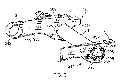
Fig. 5 shows how the axle tube 1 fitted with the
connector sleeves 2 is connected to a suspension component,
in this case a trailing arm beam 3, to form a suspension
assembly 214 at one side of a suspension system. In this
embodiment the beam 3 constitutes the "further component", in
the general terminology used herein.
The illustrated beam 3 has a hollow fabricated form. A
channel-form member constitutes the top and side walls 266 of
the beam, and a bottom plate 263 welded along the bottom
edges of the side walls 266 completes the structure. The
beam has a front end 220 with a bushing tube 242 for a pivot
connection to the frame, and a rear end 226 projecting behind
the axle location and where an air spring may be mounted.
The two side walls 266 have aligned circular openings 209
sized and spaced to receive a single connector sleeve 2 of
the axle assembly. The assembly is completed by forming
circular welds CW around the opening between the sleeve 2 and
-10-
CA 03079520 2020-04-17
WO 2019/081512 PCT/EP2018/079042
each side wall 266 of the beam 3. The convenience of a
welded-only connection is achieved but without welding
directly onto the axle. By avoiding welding directly to the
axle, local stress risers can be avoided or reduced and
durability and lifetime enhanced. Moreover the selected
solid lubricant in the connection regions between sleeve and
axle can withstand the conditions at that location during the
nearby welding, which typically might rise to about 500 C.
Since a film of the lubricant is then maintained
between the contacting surfaces of the axle tube 1 and sleeve
2, fretting and corrosion are inhibited at these areas even
under conditions of use including vibration, and an
improvement in average lifetime can be expected. The crimped
contact is sufficiently tight and uniform over the joint to
keep out water and protect the lubricated area in general
operation.
Fig. 7 shows a preferred structure at the edges 22 of
the connector sleeve 2. Here one sleeve edge 22 overlies a
corresponding edge 10 at the end of the axle tube 1, the
other sleeve edge 22 overlies the outer surface 101 of the
axle tube which extends out beyond the sleeve 2. At each
edge 22 the original "square" inner edge corner has been
machined back as an enlarged radius or chamfer, forming an
inwardly-directed edge surface portion 23 angled and spaced
away from the outer axle surface 101 and defining a
convergent groove 5 between them. The extremity of the
sleeve 2, which might tend to make frictional or fretting
engagements with the axle surface 101 during deformation
under load, then presents a rounded and gently angled surface
to minimize such potential for frictional damage.
Additionally, the groove 5 can be used to help form a
precautionary outer seal around the lubricant-containing
connection region. Fig. 8 shows, in a fragmentary cross-
sectional view, how a sealant such as a polyurethane or
silicone sealant can be applied all around the edge 22 in the
groove 5 to form a seal bead 6. The overhang of the sleeve
edge 22, over the groove 5, helps to protect the seal bead 6
against damage during subsequent use of the axle.
-11-
CA 03079520 2020-04-17
WO 2019/081512 PCT/EP2018/079042
It will be understood that not only suspension beams
but other kinds of further component, such as a brake system
element or axle spindle, can be secured to the axle in an
analogous way.
-12-