Note: Descriptions are shown in the official language in which they were submitted.
CA 03079911 2020-04-22
SELF-CLEANING FILTERING SYSTEM FOR USE IN AGRICULTURAL SPRAYERS
FIELD OF THE INVENTION
[001] The following invention report concerns the development of a self-
cleaning filtration system applied to agricultural sprayers so that the
operator does
not get in contact with residues from the applied product, relying on a
cooperative
system of a filtering element and a settling compartment, where the system is
managed by an electronic module, has obstruction sensors that communicate the
electronic module that it should send a command to revert the liquid flow
inside the
filtering element by closing valves and opening others for cleaning, sending
the dirty
liquid into the settling filter, where solid residues will be retained, and,
subsequently,
the clean liquid will go to the equipment reservoir.
BACKGROUND OF THE INVENTION
[002] The application of pesticides in plantations using a sprayer is of
paramount importance to agriculture, as pests and diseases can be controlled
by
means of this equipment, rendering agricultural production viable.
[003] Whatever the size of the cultivated area is, either in small, medium or
large rural properties, farmers will need to apply some type of pesticide,
since it is
almost unlikely that, during the production cycle, the crop will not be
affected by
diseases, pests, and invasive plants.
[004] Chemicals intended for the control of invasive plants and diseases are
traded in concentrated form (Application 870170081021, dated Oct/23/217, page
6/36 2 / 10), which requires dilution in water. In these cases, sprayers that
atomize
the liquid into droplets are usually employed.
[005] Spraying consists of reducing a great amount of liquid to droplets and
sprinkle them towards the desired target. A sprayer is a device able to
produce
droplets as a result of a certain pressure applied to a liquid.
[006] Sprayers are tools or machines that are widely used in agriculture in
order to help farmers fight weeds, insects, among others. Their major role is
to allow
the dosage of pesticide or fertilizer applications to be controlled in the
targeted area.
[007]A sprayer is primarily composed of a tank, a strainer, a pesticide pump,
a
pesticide control, a return line, line filters, and spray nozzles.
[008] The tank is intended to store the liquid ready to be applied. The tank
must be highly resistant with protection against ultraviolet rays.
[009] The role of the strainer is to filter the prepared liquid before it
passes
through the pesticide pump.
[010] The pesticide pump has the function of drawing the spray liquid from the
tank and controlling the pressure of the spray liquid after it passes through
the
pesticide pump, this pressure is around 45 to 60 pounds to allow for a
continuous
flow of the previously prepared liquid, passing through the line filters and
through the
nozzles until it hits the target.
1
CA 03079911 2020-04-22
nozzles until it hits the target.
[011] Pesticide control is done by turning spraying on and off. When it is
turned
on, the flow is directed to bars, and when it is turned off, the flow is
directed to return
(Patent application 870170081021, dated Oct/23/2017, page 7/36 3 / 10) to the
tank.
[012] The return line prevents the system from exceeding the pressure
regulated by the pesticide control, the excess spray liquid moves from the
pesticide
control back to the tank through this return line.
[013] The line filters have the role of filtering the spray liquid to avoid
obstruction of the spray nozzles.
[014] The spray nozzles have the role of turning the liquid into droplets and
hit
the target.
PRIOR ART PROBLEM
[015] In the current filtering systems of sprayers, both the strainer and the
line
filters are cleaned manually and require disassembling and cleaning, with the
line
filters being the ones that most often require cleaning. This action results
in the
operator having direct contact with the filters used for filtering
agrochemicals, with
greater exposure of the operator to agrochemicals and greater risk of
contamination.
An example of this can be seen in the US document no. 20050205486, which shows
a filtration device with a removable filter.
[016] There are also self-cleaning filters, as in US 7192528, which describes
a
self-cleaning filter system including an inlet fitting that is adapted to be
inserted into
an existing filter body. A spraying tube that has a plurality of outlets that
fit slidingly
into the inlet fitting is positioned on the existing filter ring discs and a
compression
member near one end of the ring discs applies compressive force to the ring
discs.
When the fluid enters the spraying tube, the compression of the inlet filling
on the
ring discs is reduced to allow (Patent 870170081021 dated Oct/23/2017, page
8/36 4
/ 10 ) the ring discs to separate from one another, while the pressure of the
fluid is
simultaneously imposed upon the ring discs by a plurality of outlets in order
to clean
the filter component. The parts included in the system can be used to convert
a
manual filter into a self-cleaning filter system.
[017] However, there is no control and management of the filtering operation
even in the self-cleaning system.
PROPOSED SOLUTION
[018] Currently, no self-cleaning filtration system applied to agricultural
sprayers having obstruction sensors and sensors indicating the need to replace
filters
or recommending the time to replace them is known in the prior art.
SUMMARY
[019] Thus, due to considerations pertinent to the prior art previously
discussed, one of the objectives of the present invention is to develop a
filtration
system applied to agricultural sprayers, with the system having several
components
2
. .
CA 03079911 2020-04-22
that are described as follows:
[020] The filtration unit (UF) is composed of a filtering element, a header, a
filter body coupled to a head, solenoid valves and an NA pressure switch. This
unit
receives the mixture of water and pesticides (ADF) from inside the main tank
of the
equipment to the hoses and applicator nozzles.
[021] The settling unit (UD) is composed of a reservoir suited for a paper
filter.
This unit receives residues with some amount of the ADF mixture from the
filter after
cleaning. This material must be ecologically disposed of (Patent 870170081021,
dated Oct/23/2017, page 9/36 5 /10) and the ADF will be cleaned and sent to
the
reservoir of the equipment through the return hose.
[022] The supply unit (UA) is composed of valves that are electronically
commanded. Its performance is set by the user who will choose, in the UE
(electronic
unit), how many liters of water should be poured into the main tank of the
equipment
and, once the selected value for the liquid has been reached, the UE unit acts
on
these valves discontinuing the flow and diverting the water to the reservoir
tank.
[023] The Plus filter system (SSF) model consists of LEDs, a manual cleaning
button, an on/off button and an electronic board. Each LED provides different
information, one LED informs that the system is on, another informs that the
filter is
dirty and yet another informs that cleaning is in progress. The purpose of
this unit is
to electronically control the ADF filtering action.
[024] The master filtration system (SMF) model consists of an LCD screen, a
numeric keypad, an on/off button, a manual cleaning button and an electronic
board.
The objective of this unit is to electronically command the ADF filtering
action.
[025] The Premium filtration system (SPF) model consists of a touch screen, a
manual cleaning button, an on/off button and an electronic board.
DESCRIPTION
The present invention is illustrated by means of drawings representing the
filtration system applied to agricultural sprayers, in such a way that the
product can
be fully reproduced by an appropriate technique, allowing for the full
characterization
of the functionality of the claimed object.
[027] The figures that express the best (Patent 870170081021, dated
Oct/23/2017, page 10/36 6 / 10) form or the preferred form of embodiment of
the
devised product are the basis of the descriptive part of the report, using
detailed and
consecutive numbering, which clarifies aspects that may be implied by the
adopted
representation in order to clearly determine the patent sought here.
[028] These figures are merely illustrative and may present variations as long
as they do not deviate from the initial application.
[029] In this case:
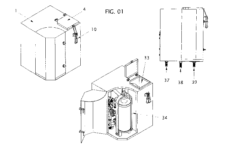
[030] FIGURE 1 shows a perspective of the proposed filtration system;
[031] FIGURE 2 shows the location of the filtering element;
3
. .
CA 03079911 2020-04-22
[032] FIGURE 3 shows the assembly of the components of the invention;
[033] FIGURE 4 shows an exploded view of the equipment;
[034] FIGURE 5 shows a perspective of the electronic assembly;
[035] FIGURE 6 shows the strainer;
[036] FIGURE 7 shows a perspective of the settling filter;
[037] FIGURE 8 shows the assembly of the settling filter;
[038] FIGURE 9 shows an example of the system as a whole;
[039] FIGURE 10 shows the self-cleaning filter and its constituent parts;
[040] FIGURE 11 shows the supply unit (Patent 870170081021, dated
Oct/23/2017, page 11/36 7 /10).
[041] FIGURES 12 and 13 show the supply unit and exploded views.
]042] The proposed filtration system uses a casing (1) containing a settling
compartment (33) provided with a lid (4) and an open/close clamp (10) to
maintain
the settling filter (36), a compartment (34) of the filtering element or self-
cleaning filter
(14), provided with a lid (35), to maintain the self-cleaning filter (14),
said casing (1)
also containing, at its base, an inlet for the fluid to be filtered (37), a
pesticide control
(38) outlet, and a return (39) outlet.
[043] Inside the compartment (34) of the filtering element (14), there is a
supporting cylinder (11) , and inside this supporting cylinder (11) the fluid
diffuser (15)
and the filtering element (14) are seated, and this supporting cylinder (11)
is secured
by a fixing handle (18) and by a fixing spindle (17), and said handle (18) can
tilt,
releasing the cylinder head (16) and, consequently, the filtering element
itself (14) for
replacement.
[044] Said filtering element (14) is composed of internal vanes (65) and
external vanes (66), which are held in grooves present on the flanges (63 and
64),
where said flanges (63 and 64) are attached to the upper and lower fasteners
(67),
and a 150p cylindrical mesh (68) is arranged around it.
[045] The filtering element assembly (14)1 is controlled by an electronic
module (41) containing an outlet connector for IHM (42) and another connector
(43)
that is connected to the valves (44, 45, 46, and 47), and said module also
controls
4
. .
CA 03079911 2020-04-22
the primary pressure transducer (48) and the secondary pressure transducer
(49),
and it is also possible to see the inlet for the fluid to be filtered (37),
the outlet for
pesticide control (38), and the outlet (50) for the settling filter (36).
[046] Figure 04 shows an exploded view of the equipment, in which we can
see the casing (1), a screw (2) and a nut (3) for fixing the lid (4), a
primary hose (5),
an adapter (6), a solenoid valve (7), an NPT 1 'terminal (8), a hose (9), the
sealing
ring (10) of the cylinder (11) of the filter (14), a sealing ring (12), the
base (13) of the
cylinder (11) of the filter (14), a fluid diffuser (15), the head (16) of the
cylinder (11), a
spindle (17), the fixing handle (18) of the cylinder (11), a bushing ( 19), a
flanged
bushing (20), a screw and a nut (21 and 22), an NPT panel terminal 1'x1(23), a
solenoid valve (24), an NPT T adapter 1' x 1 'x 1' (25), a secondary hose
(26), a
secondary pressure transducer (27), a solenoid valve (28), a long panel
terminal 1 'x
1' x 1 '(29), an NA solenoid valve (30), an NPT terminal 1' x NPT 1/4 x 1'
(31), a
primary pressure transducer (32), and an M12 x 30 screw (33).
[047] The electronic module (41) allows three outlets, one of them for
connection to the spray shutdown sensor (51), another for connection to the
HMI unit
(52) and the other (53) connected to fittings connected to the equipment
battery.
[048] Once the spray shutdown sensor of the equipment detects that spraying
was discontinued by the operator to perform maneuvers, for example, in
conjunction
with information from the pressure transducers (27 and 32), the electronic
unit (41)
will send a command for the valves to operate, so that they invert the flow in
the filter,
sending this material to the solenoid valve (47), which will be open and will
send the
liquid to the settling unit, thus performing the cleaning operation. The
liquid comes
from the settling unit, which has a filter to retain micro particles arising
from the
strainer and then returns to the reservoir of the equipment.
[049] In section A-A of figure 6, we can see the outlet for the settling
filtration
fluid (54), the filter outlet (55) and the fluid inlet (56) at the upper
portion of the filter
(14).
[050] The settling filter (36) contains rigging (57) to be tied to the end of
the
flange (58), and said filter (36) must be replaced periodically and disposed
of in an
environmentally friendly way.
[051] Figure 9 shows the internal circuit including the tank/reservoir (59),
settling filter (36), relief valve (60), pesticide pump (61), valves (44, 45,
46 and 47),
primary (48) and secondary (49) pressure transducers, filtering element (14),
spray
shutdown sensor ( 51), pesticide control (38), and spray nozzles (62).
[052] At the time of spraying, the water/pesticide mixture fluid gets out of
the
CA 03079911 2020-04-22
tank (59), passes through the feeding pump (61) and then through the hose and
gets
into the UNF solenoid valve (7), which will be open. This fluid will be
released into the
filter by a fluid diffuser (15). The filtration mash of the filtering element
(14) will retain
potential solid particles, and the liquid will proceed to the applicator
nozzles (62)
located on the bars.
[053] The supply unit (UA) that is composed of a three-way valve (69), which
receives, connected to it, an adapter (71) and two terminals (72 and 73), with
the
adapter (71) connected to a flow meter (70), the terminal (73) being connected
to a
nut (75) that secures this terminal (73) to the housing (76), which is closed
by screws
(74), in such a way as to expose the terminals (72 and 73), the terminal (79)
of the
flow meter (70) and the connector (77) with the cable and its connector (78)
in the
electronic unit. (Patent application 870170081021, dated Dec/13/2017, page
14/36
/ 10).
[054] Another function of this system is to prevent manual contact of the
operator with chemical elements and allow for taking care of the environment,
as
most farmers clean the existing filters in the sprayers while filling their
tanks most
often on river banks.
6