Note: Descriptions are shown in the official language in which they were submitted.
CA 03080295 2020-04-24
WO 2018/078221 1 PCT/F12017/050743
Apparatus and method for comminuting of material
Background of the invention
There exists a great need for comminuting of material in the mining,
mineral, and cement industries. The noteworthy issue is that comminuting mate-
rial is the biggest energy-consuming process of these industrial sectors.
The energy consumption required by the comminuting process de-
pends on the material type and its magnitude is typically 20-60kWh/t, but in
fine
comminuting may be as much as 100-1000 kWh/t.
Friction and the heat it causes takes up most of the energy consump-
tion in comminuting. The main part of the amount of energy required is used at
the grinding stages, the costs of which in a mineral concentration process may
be
up to 70% of the concentration costs.
Some of the prior art apparatuses and methods are disclosed in publi-
cations US2981486, US1704823 and GB709729.
There are, however, problems associated with the prior art methods.
The problem with the prior art methods and apparatuses is their high energy
consumption and modest efficiency. A further problem is the low quality of the
end product, that is, the fine particles, due to the breaking manner of the
particles
based on fast compression, which leads to arbitrary fracture planes in the
area of
principal stress fields, and the formation of a hyperfine fraction which is
difficult
to process.
Summary of the invention
An object of the invention is thus to develop an apparatus and a meth-
od so as to solve or alleviate the above problems.
The object of the invention is achieved by an apparatus and method
which are characterized by what is stated in the independent claims. Preferred
embodiments of the invention are disclosed in the dependent claims.
The invention is based on a new kind of mutual positioning of convey-
or surfaces, which in turn allows free crushing, in other words, particle-
specific
slow compression of solid material and its weakening by increasing micro-
cracks.
The advantage of the inventive apparatus and method is low energy
consumption, a high-quality end product, as well as a well-defined and
reliable
device structure. The invention additionally makes it possible to divide the
end
products into material flows according to different particle sizes.
CA 03080295 2020-04-24
WO 2018/078221 2 PCT/F12017/050743
Brief description of the figures
The invention will now be described in more detail in connection with
preferred embodiments and with reference to the accompanying drawings, in
which
Figures 1-3 are top views of the apparatus from different height levels,
examined in the transverse direction in relation to the direction of movement
of
the conveyor surfaces, and illustrating the changing of the wedge angle at
differ-
ent heights, the point of examining proceeding in the transverse direction in
rela-
tion to the direction of movement of the conveyor surfaces,
Figure 4 illustrates, from the top, the principle of the position of the
conveyor surfaces of the comminuting apparatus at the inlet, examined in the
transverse direction in relation to the direction of movement and illustrating
the
wedge angle, that is, convergence of the conveyor surfaces in the direction of
movement.
Figure 5 illustrates the principle of the position of the conveyor sur-
faces of the comminuting apparatus from the first end, that is, the front end,
ex-
amined in the direction of movement and illustrating the nip angle, that is,
the
convergence of the conveyor surfaces detected in the transverse direction in
rela-
tion to the direction of movement.
Figure 6 is a schematic view of the conveyor structure, illustrating the
adjustment structures,
Figure 7 is a schematic diagram of the apparatus from the side and
compression in that context, material particles, daughter particles, and
subparti-
cles of daughter particles.
Detailed description of the invention
The invention relates to comminuting of material by compression, by
way of example in particular to comminuting of elastoplastic material.
Minerals,
for example, serve as an example of a comminutable, at least partly
elastoplastic
material. If the material is homogeneous and fully elastic, the stress field
formed
in the material is distributed according to the location of the compression
points
and surface area in the material, and the stress field may be calculated
relatively
accurately based on the bond strength between atoms. In practise, all the
commi-
nutable material particles are non-homogeneous and at least slightly plastic,
and
they typically include a plurality of matter components unevenly distributed
in
the material and which have discontinuity points and micro-cracks at their
CA 03080295 2020-04-24
WO 2018/078221 3 PCT/F12017/050743
boundary surfaces, in particular. In addition to minerals, ceramic material
and
glass are elastoplastic material.
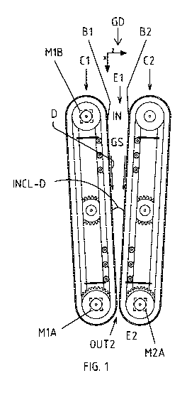
The apparatus GD shown in the figures comprises a first conveyor
structure Cl having a first conveyor surface Bl. The apparatus also comprises
a
.. second conveyor structure C2 having a second conveyor surface B2. Both
convey-
or surfaces Bl, B2 are conveyor surfaces rotatable in the direction of
movement
D, in a way like a chain track, which rotates according to its closed-loop
shape full
rotations supported by its support structure SS and powered by one or more mo-
tor MIA, M2A or another actuator M1A, M2A. The actuator M1A, M2A rotating the
conveyor surface Bl, B2 is an electric motor or a hydraulic motor or another
ac-
tuator, for example. The actuator M1A, M2A forms means for bringing the con-
veyor surfaces Bl, B2 in a movement in the direction of movement D where the
two conveyor surfaces Bl, B2 placed to face each other are arranged to move
from a first end El of the conveyor structures Cl, C2 towards a second end E2
of
.. the conveyor structures. It is obvious that at the second end E2 of the
apparatus,
the movement direction of the conveyor surfaces becomes the opposite as the ro-
tation movement of the conveyor surfaces Bl, B2 turns the movement into the re-
turn direction, but the movement in the return direction takes place at the
outer
sides of the pair of conveyor structures Cl, C2 and is at the rear end, so the
sec-
ond end E2, towards the front end, so the first end.
However, what is essential in the apparatus is the structures defining
the comminuting space GS, so the edges of the area where the conveyor surfaces
Bl, B2 face each other. As mentioned, the conveyor surfaces Bl, B2 define the
comminuting space GS.
At least at one end of the conveyor surfaces Bl, B2, the conveyor struc-
tures Cl, C2 have under the conveyor surface, a drive wheel, drive gear of a
simi-
lar drive transmitter GE1, GE2 that transfers the rotational force provided by
the
actuator M1A, M2A to the conveyor surface Bl, B2. In addition, the conveyor
structures have at the opposite end idler wheels TR1, TR2 on which the
conveyor
surfaces Bl, B2 pass and turn into the return movement. Figures 1-3 show the
drive wheels GE 12, GE22 also in the area between the ends, such as in the
centre
area of the conveyor structure.
The apparatus structure is such that the means MIA, M2A for bringing
the conveyor surfaces Bl, B2 into a movement in the direction movement D are
arranged to bring the conveyor surfaces Bl, B2 into a rotational movement ac-
cording to successive full rotations.
CA 03080295 2020-04-24
WO 2018/078221 4 PCT/F12017/050743
In addition, the conveyor structure such as Cl, C2 comprises a support
structures SS1, SS2 to support the rotational movement of its conveyor surface
Bl, B2, the support structure may be accomplished with supporting rolls, and
naturally it is plausible to see the aforementioned idler wheels TR1, TR2 as
in-
cluded in the support structures and likewise the drive wheels GE1, GE12, GE2,
GE22.
The conveyor surface such as B1 and correspondingly B2 is, as men-
tioned in the above, a closed loops that rotates successive full rotations
supported
by drive wheels GE1, GE12 and correspondingly GE2, GE21, as well as idler
wheels TR1 and correspondingly TR2, and also the support rolls SS1 correspond-
ingly SS2.
Referring to Figures 1-3 and 6, the axle Al of the drive wheel GE1 is fit-
ted with a bearing BR1 to a support member SM1 such as a slide rail SM1 by
means of which an actuator HM1 such as a hydraulic actuator moves the lower
end of the axle Al in relation to the fixed frame FR of the apparatus (frame
FR
shown partially).
Correspondingly, the axle A2 of the idler wheel TR1 is fitted with a
bearing BR2 to a support member SM2 such as a slide rail SM2 by means of which
an actuator HM2 such as a hydraulic actuator moves the lower end of the axle
A2
in relation to the fixed frame FR of the apparatus.
Figures 1-3 and 6 do not show the frame of conveyor because it would
cover the top part of the conveyor, among other things, so the structures that
the
figures show of the conveyors Cl, C2.
Between the ends of the conveyor such as Cl there may be other verti-
cal axles between axles Al, A2, and their ends may have device structures as
the
ones disclosed. There may be another number of drive wheels than the two drive
wheel pairs in the example of the figures.
In the apparatus, the first conveyor surface B1 and the second convey-
or surface B2 are positioned facing each other. This way, the conveyor
surfaces
Bl, B2 are arranged to define the comminuting space GS where the material is
comminuted by the compression provided by the moving conveyor surfaces Bl,
B2.
From the point of view of the material to be comminuted, the appa-
ratus comprises an inlet IN, and from the point of view of material already
com-
minuted, the apparatus comprises outputs OUT1 and OUT2. Output OUT 1 is at
the substantially horizontal lower edge of the apparatus and in practise it is
a gap
CA 03080295 2020-04-24
WO 2018/078221 5 PCT/F12017/050743
left between the lower edges of the conveyor surface pair B1, B2, which
extends
at the lower edge of the conveyor towards the rear end E2. Output OUT2 is at
the
rear end E2 of the apparatus, where the movement direction D is aimed, in prac-
tise output OUT2 is the end point of the area facing each other in the
conveyor
surfaces B1, B2 at the second end E2, so the rear end, of the conveyor
structures
Cl, C2.
To subject the material to compression, the structure is such that in
the apparatus the conveyor surfaces B1, B2 positioned to face each other are
placed in a convergent manner so that the gap between the conveyor surfaces
B1,
B2 narrows when examined in the movement direction D of the conveyor surfac-
es, so that the advancing movement of the conveyor surfaces B1, B2 is arranged
to
bring about compression in the material being comminuted.
The convergence angle of the convergence in the movement direction
of the conveyor surfaces, that is, the wedge angle, is marked with INCL-D in
Fig-
ures 1-3 and 4.
The convergence angle, transverse in relation to the movement direc-
tion of the conveyor surfaces, is marked with nip angle INCL-TD. The angle
INCL-
TD is in Figure 5 upward-opening (so downward converging) angle between the
conveyor surfaces B1, B2.
Referring to Figure 5 and 7 and the comparison in Figures 1-3, the core
of the invention is that in the apparatus the conveyor surfaces B1, B2 are in
a
double-converging manner so that in addition to said convergence in the move-
ment direction (direction D), so narrowing, the conveyor surfaces B1, B2 are
addi-
tionally placed in a convergent manner so that the gap between the conveyor
sur-
faces B1, B2 also narrows in the transverse direction TD in relation to the
move-
ment direction D. This
way, the comminuting space GS becomes double-
convergent. In its clearest form, this convergence in the transverse direction
TD,
so nip angle INCL-TD, in relation to the movement direction D, is seen in
Figure 4
where the movement direction is away from the viewer.
In the comminuting space GS the transverse convergence, so the nip
angle INCL-TD (Figure 5), decreases towards the rear end E2 so that the width
of
the lower part of the comminuting space GS remains the same of decreases ac-
cording to the nip angle INCL-D set (which changes in the vertical direction,
so
decreases downward), and so that the nip angle INC L-TD (Figure 5) is zero at
the
open rear end E2 of the comminuting space GS, which means that the distance be-
tween the walls of the comminuting space GS, that is, the conveyor surfaces
B1,
CA 03080295 2020-04-24
WO 2018/078221 6 PCT/F12017/050743
B2 at the open end E2 at the output OUT2 is the same as the width of the
output
OUT1 of the lower part at its narrowest. In the method according to the inven-
tion, material is sorted, transported and cracked into sufficiently fine-
grained ma-
terial everywhere in the comminuting space GS, in particular in successive are-
as/places of the comminuting space GS in the movement direction as mentioned,
and comminuted material is removed from all parts of the comminuting space
Due to the joint effect of these functions, the compression and cracking of
parti-
cles is mostly realized in a layer one particle thick and particle-
specifically, and
always with a force that always matches with the breaking strength of the
particle
regardless of its tensile properties. The comminuting of particles is
performed at
temporally successive stages so that after comminuting a particle MP, the
commi-
nuting of its daughter particle MPD1, that is, a daughter piece MPD1 is
carried out
at a spot that is both at a lower position between the conveyor surfaces B1,
B2
and at the same time further in the movement direction D, correspondingly the
comminuting of the subparticle MPD2 of the daughter particle MPD1 is per-
formed at a spot that is also at a still lower position between the conveyor
surfac-
es B1, B2 and at the same time further still in the movement direction D. This
way,
a longer dwell time, that is, processing time in compression, is achieved for
the
smaller particles, so the daughter particles and subparticles MPD2 comminuted
from them.
Although the top view Figures 1-3 and also in Figure 4, the conver-
gence angle INCL-D, so nip angle, of the convergence in the movement direction
may be detected as regard the angle, by comparing Figures 1-3 another issue
may
be noticed, that is, an issue related to the nip angle INCL-TD (Figure 5),
that is, a
.. convergence angle of convergence transverse in relation to the movement
direc-
tion of the conveyor surfaces. This is because in Figures 1-3 the conveyor
surfaces
B1, B2 are in the different figures (different height positions) at different
distanc-
es from each other, and when it is taken into account that Figures 1-3 are
concep-
tual views from a different height, that is, in Figure 1 the height position
of exam-
ining is the top part of the conveyor surfaces, in Figure 2 the height
position of ex-
amining is the centre part of the conveyor surfaces.
With reference to Figures 1-3 and 4, according to the applicant's ob-
servations a suitable degree for convergence, that is, wedge angle INCL-D at
the
level of the top part of the conveyor surfaces B1, B2 (as in Figure 1), in
particular,
is approximately 5-10 degrees, by way of example 8 degrees shown in Figure 1.
But since these are two opposite conveyor surfaces B1, B2, so placed facing
each
CA 03080295 2020-04-24
WO 2018/078221 7 PCT/F12017/050743
other, inclined into different directions, the inclination position of both
conveyor
surfaces B1, B2, so at the top part of the conveyor surface pair, in such a
case one
half of the aforementioned degrees, that is, 2.5-5 degrees, in relation to the
centre
line CL passing between the conveyor surfaces. The top part U and lower part L
.. of the conveyor surfaces are best seen in Figures 5 and 7.
The comminuting ration, that is, crushing ration refers to the ratio be-
tween the size of the inlet IN and output OUT1 of the apparatus, and it is
between
5-15. for example. The size of the inlet should be taken as a function of
varying
height as in Figures 1-3 depending on the height position of the point of
examin-
ing (conveyor top part Figure 1, centre part Figure 2, lower edge Figure 3).
Fig-
ures 1-3 additionally show that the wedge angle varies from the 8 degrees at
the
top part (Figure 1) inlet - feed edge to the 0 (zero) degrees at the lower
edge (Fig-
ure 3) of the conveyor Figures 1-3 are horizontal plane, cross-cut, principled
views from three planes: Figure 1 top edge where the wedge angle is 8 and the
crushing ratio hence approximately 14, Figure 2 centre level between the top
and
lower edge where the wedge angle INCL-D is 4 and the crushing ratio approxi-
mately 7.5 and in addition Figure 3 from the lower edge of the conveyor pair,
so at
the level of the lower output that is output OUT 1 of the material where the
wedge
angle INCL-D is approximately 0.5. To be precise, the conveyor surfaces B1, B2
travel along a slightly curved line on the side of the comminuting space GS,
the
mutual distance between the conveyor surfaces B1, B2 approaching a distance
that corresponds to the set value of the output at the lower part L and rear
end E2
of the comminuting apparatus/crusher. The output OUT1 at the lower edge may
either be straight (as seen in the movement direction D) or slightly wedge-
like,
that is, for example 0.5 degree in Figure 3 so that a particle that has
stopped just
above the lower edge is compressed before exiting the end E2, but is not neces-
sarily broken. Such a weakening may be important in a further process (for ex-
ample, dissolving) where product particles should have as many micro-cracks as
possible.
The magnitude of the wedge angle INCL-D (Figure 4), that is, the con-
vergence between the conveyor surfaces B1, B2 in the conveying direction, so
the
movement direction, depends of the height level being examined (Figures 1-3
from different height levels) and on how the magnitude of the nip angle INCL-
TD
(Figure 5) changes in this direction. In an embodiment, the wedge angle (INCL-
D)
is the largest at the top parts of the comminuting space GS (Figure 1) and its
value
decreases towards the lower height levels and is at its lowest at the level of
the
CA 03080295 2020-04-24
WO 2018/078221 8 PCT/F12017/050743
lower edge (Figure 3), where it may be set to zero or otherwise very low. This
is
why in the comminuting space GS the smallest particles MPD1, MPD2 stopped at
the lower levels travel a longer distance during compression and compression
is
thus slower than with the larger particles MP.
With reference to Figures 5 and 7, in particular, in an embodiment the
apparatus is such that the conveyor surfaces B1, B2 which are placed facing
each
other which may be brought into movement are arranged to comminute one or
more material particles MP comprised by the material for forming one or more
smaller daughter particles MPD1 from the material particle MP. It is further
the
case that the conveyor surfaces B1, B2 that create the convergence in the
trans-
verse direction TD in relation to the movement direction are arranged lower in
the comminuting space GS to stop the falling movement of such a daughter parti-
cle MPD1 formed in the comminuting space GS, to focus a movement in the
movement direction on conveyor surfaces B1, B2 also to the daughter particle
MPD1. This way, the daughter particle proceeds in the movement direction D1
and because the comminuting space is converging, so narrowing, in the move-
ment direction as in Figure 4 and 1, for example, the daughter particle MPD1
will,
at some point of proceeding, be met with such a tight compression that it
breaks
and from the daughter particle a smaller subparticle MPD2 is created, which as
Figure 7 shows falls downward until it stops (as the daughter particle MPD1
but
at a lower position and having proceeded further in the movement direction D)
between the conveyor surfaces B1, B2 reaching a movement in the movement di-
rection, and the subparticle exits the vertical end gap at the rear end E2 of
the de-
vice.
Depending on the length of the conveyor surfaces, the device settings
(speed of motion of the conveyor surfaces, nip angle, wedge angle) and the
parti-
cle size of the incoming material, there may also be more height positions for
the
compression point (three in the above) and particle size categories (three in
the
above, so incoming particle MP, daughter particle MPD1, and subparticle MD2 of
daughter particle).
If the size of the subparticle MPD2 is already smaller than the exit gap
OUT1 at the lower edge, the "finished" subparticle MPD2 can exit through
output
OUT1.
It may obviously also be the case that the incoming particle MP or
daughter particle MPD1 is already small enough to exit through the output OUT1
at the lower edge.
CA 03080295 2020-04-24
WO 2018/078221 9 PCT/F12017/050743
Consequently in the invention, the grading/distribution, conveying
and cracking is repeated everywhere in the comminuting space GS particle-
specifically in a layer no more than one particle thick.
It is detected that the direction TD, transverse in relation to the
movement direction D, in which direction said transverse convergence exists be-
tween the conveyor surfaces, is a substantially perpendicular transverse
direction
in relation to the movement direction D of the conveyor surfaces. It is
further-
more the case that the existing conveyor structures are so positioned that the
movement direction D of the conveyor surfaces is substantially horizontal.
Further, the conveyor structures facing each other are so placed that
the direction TD transverse in relation to the movement direction D of the con-
veyor surfaces is substantially vertical.
This being the case, referring in particular to Figures 1-3, 4-5 and 7,
the comminuting is performed in the vertical direction (such as TD) and also
in
the horizontal direction (such D) in the converging, wedge-like comminuting
space GS, the walls of which, so the conveyor surfaces Bl, B2, move in the
hori-
zontal movement direction D towards the gap-like end, that is, the output
OUT1,
and the wedge angle of which, so the convergence of the comminuting space GS
in
the movement direction decreases in the movement direction of the walls, so
the
conveyor surfaces Bl, B2, and from the top part of the front end El of which
the
feed particles, that is, the particles MP in their original size, are dropped
into the
mouth formed by the walls, that is, the conveyor surfaces Bl, B2 at the inlet
IN.
The feed particles smaller than the gap-like lower part, so the output
OUT1, in the comminuting space GS, fall freely in the vertical direction or,
if need
be, assisted by a gas or fluid flow, and exit the comminuting space at its gap-
like
output OUT1 at its lower edge.
Alternatively, feed particles larger than the gap-like lower part, so the
output OUT1, are graded by stopping (because of the convergence according to
the nip angle INCL-TD in the transverse direction in relation to the movement
di-
rection D, that is, vertical direction) at the height levels according to
their sizes,
that is, between the conveyor surfaces Bl, B2. The walls, so the conveyor
surfaces
Bl, B2, of the comminuting space GS then carry the particles in the movement
di-
rection D towards the rear end E2 and at the same time compress the particles
that have got wedged between the walls, that is, the conveyor surfaces Bl, B2,
which may exit directly from the gap-like output OUT2 of the comminuting space
GS, or before that crack according to their breaking strength and whereby the
CA 03080295 2020-04-24
WO 2018/078221 10 PCT/F12017/050743
created daughter particles (or the latter subparticles MPD2 of the daughter
parti-
cle) fall in the comminuting space vertically lower either through the output
OUT1 at the lower edge, or if the transverse (in relation to movement
direction)
convergence of the comminuting space GS, so in practise the conveyor surfaces,
stops the daughter particle MPD1 still too large, the conveyor surfaces B1, B2
transport the daughter particle in the movement direction towards the output
OUT2 in which case the daughter particle MPD1 either breaks during the move-
ment and creates the subparticle MPD2 or exits from the output OUT2 at the
rear
end E2 of the device. Correspondingly, the subparticle MPD2 either drops into
the
output OUT1 or due to the nip angle stops before the output OUT1 and joins the
movement of the conveyor surfaces into the direction D towards the output OUT2
at the rear end.
This way, a long dwell time is achieved for the daughter particles
MPD1 and their subparticles MPD2, that is, a slow compression which improves
the compression and the comminuting quality. In the invention, particles are
compressed slowly and widely enough so that the maximum number of micro-
cracks weakening the material would develop into the material. Slow compres-
sion is an energy-efficient way to comminute material. In slow compression,
the
probability of a compression member to create additional, unwanted kinetic en-
ergy and friction to the daughter pieces is the smallest. Furthermore, slow
com-
pression results in more evenly sized daughter pieces that is daughter parti-
cles/subparticles and less non-selective small daughter pieces/subpieces in
the
areas of the principal stress fields than a fast, impact-like loading.
Slow compression is implemented successively, also for the daughter
pieces created in the cracking, and repeated (that is, the stopping of the
falling of
the daughter piece due to the nip angle and the continuation of the movement
in
the movement direction made possible by the stopping) until the size of the re-
sulting particles is small enough, so smaller than the output OUT1 at the
lower
part of the device. Elastic energy stored between the compressions in the com-
pressions is released and the particles must have the chance to change their
posi-
tion before the subsequent compression stage leading to cracking. The
repetition
of such compression-release stages enhances the creation and growth of micro-
cracks in the particle parts remaining intact. The compression-release cycles
are
implemented so that the material gradually weakens in all the size categories
un-
dergoing compression, also in the size categories preceding the product size
(so,
the size going to the output OUT1).
CA 03080295 2020-04-24
WO 2018/078221 11 PCT/F12017/050743
Referring to Figure 5 and 7 and the comparison in Figures 1-3, the core
of the invention is that in the apparatus the conveyor surfaces B1, B2 are in
a
double-converging manner so that in addition to said convergence in the move-
ment direction (direction D), so narrowing, the conveyor surfaces B1, B2 are
addi-
tionally placed in a convergent manner so that the gap between the conveyor
sur-
faces B1, B2 also narrows in the transverse direction TD in relation to the
move-
ment direction D. This way, the comminuting space GS becomes double-
convergent. In its clearest form, this convergence in the transverse direction
TD,
so nip angle, in relation to the movement direction D, is seen in Figure 4
where
the movement direction is away from the viewer.
According to the observations of the applicant, a suitable nip angle
(INCL-TD (Figure 5) is, for example, 5-20 degrees. This depends of the
particle
size and size distribution of the material, for example.
The size of the material particles MP coming in to the inlet IN is be-
tween 0.10 - 200 mm, for example.
The comminuted particle size obtained from the output OUT1 is be-
tween 0.1- 5 mm, for example. A suitable speed of motion for the conveyor sur-
faces B1, B2 in the movement direction D, as created by the motors M1A, M2A,
is
0.02 - 0.5 m/s, for example. In connection with the motors, or controlling the
mo-
tors, there may be a control unit by means of which the speed of the conveyor
sur-
faces B1, B2 may be adjusted, in particular so that the speed of motion of the
con-
veyor surfaces B1, B2 slightly differs from each other. So, the speed of
motion of
the conveyor surfaces B1, B2 maybe adjusted to slightly differ from each
other.
The purpose of the speed difference is to increase the effective ares of
compres-
sion and to cause shear forces and twisting forces in the particle, increasing
the
micro-cracks. To avoid wear and tear as well as friction, the speed difference
must be small, at most 5%, for example.
With the inventive calculated rubbing, the load is directly aimed at the
particles. By deliberately making use of the speed difference between the
convey-
or surfaces B1, B2 to create rubbing, small particle sizes are accomplished
with a
significantly lower volumetric energy consumption.
The following is remarked about the conveyor surfaces B1, B2. Refer-
ring to Figures 4-5 and 7, for example, the conveyor surfaces B1, B2 comprised
by
the conveyor structures Cl, C2, compression lamellas PL may be slightly turned
(either due to their material or fastening) or on the compression lamellas PL,
or
otherwise, there may be fastened an elastic, continuous band which may be
CA 03080295 2020-04-24
WO 2018/078221 12 PCT/F12017/050743
smooth or patterned (symmetrically or asymmetrically, for example) in various
ways. The purpose of the elastic layer of the conveyor surfaces B1, B2 is to
in-
crease the surface area the particle is subjected to when compressed. The pur-
pose of the shaping of the conveyor surfaces B1, B2 is to prevent the material
pieces from sliding backwards and to boost the cutting force components of the
compression. In an embodiment, the thickness and elasticity of the elastic
layer is
larger in the top part of the conveyor surfaces B1, B2 (than in the lower
part), in
which top part the transitions leading to cracking are larger due to the
bigger size
of the particles, compared to the lamellas at the lower part where the wedge
load
is lighter.
To be discussed next are adjustment structures AD1-AD4 shown in
Figure 6, for adjusting the position/location of the conveyor structures Cl,
C2 or
their conveyor surfaces B1, B2 Figure 6 is a schematic view of the conveyor
struc-
ture, illustrating the adjustment structures. The adjustment may be performed
on
the conveyor structure Cl, C2 or directly on the actual conveyor surface B1,
B2.
It is a good idea to be able to adjust one or more of the following:
adjustment of the convergence angle INCL-D of the convergence in the movement
direction, so the wedge angle, adjustment of the convergence angle INCL-TD of
the convergence in the direction TD transverse in relation to the movement
direc-
.. tion D, so the nip angle, adjustment of the distance between the conveyor
surfaces
B1, B2 and/or adjustment of the speed of motion of the conveyor surfaces.
The device structures for performing the various adjustments may be
partly or entirely the same device structures AD1-AD4. The apparatus thus com-
prises adjustment means AD1-AD4 for the conveyor surfaces B1, B2 for adjust-
ing the convergence angle INCL-D of the convergence in the movement direction,
so the wedge angle, and the same or different adjustment means for adjusting
the
convergence angle INCL-TD of the convergence in the direction TD transverse in
relation to the movement direction D, so the nip angle, and the same or
different
adjustment means for adjusting the speed of motion and distance between the
conveyor surfaces B1, B2.
Figure 6 shows the adjustment means AD1-AD4 of one conveyor struc-
ture Cl, the structures may be similar in the second conveyor structure C2,
also
(Figure 6 only show a bottom corner), the location of which would in Figure 6
be
on the left side of the conveyor structure Cl or in parallel with it.
CA 03080295 2020-04-24
WO 2018/078221 13 PCT/F12017/050743
In Figure 6, the adjustment means AD1-AD4 may be mutually similar,
so the structure of the adjustment means is discussed as relates to the
adjustment
means AD1, in particular.
In Figure 6, the conveyor structure Cl is shown as seen from the inlet
side IN at the front end El. Figure 6 shows end axles Al and A2 of the
conveyor
structure, and at the lower end of the axle Al, a rotating motor MIA and at
the
lower end A2 a rotating motor M1B, if required.
The adjustment means AD1 comprise an actuator HM1, such as a hy-
draulic motor / hydraulic piston HM1, and a support member SM1 such as a slide
rail SM1 by means of which the actuator HM1 moves in the spot in question a
sub-
entity that includes the end axle Al with its bearing housing, the drive gear
GE1,
rotating motor MIA of the end axle.
Each of the conveyor structures Cl, C2 may be separately adjusted
with the adjustment means AD1-AD4 within the limits set for the device. By mov-
ing the conveyor structure, the distance between the conveyor surfaces Bl, B2
as
well as the nip angle INCL-TD and wedge angle INCL-D are adjusted, so the rela-
tive transition created by the conveyors and the sizes of the inlet IN or
output
OUT1, OUT2 may be adjusted. The conveying speed of each conveyor surface Bl,
B2 consisting of lamellas and/or a belt is adjusted according to the material
prop-
erties and capacity with the speeds of the motors M1A, M2A.
The adjustment of the wedge angle INCL-D, so the convergence in the
movement direction, is performed for the conveyor Cl by adjusting, with the ad-
justment structures AD2 (actuator HM2, in particular), AD4 at the front edge
El
of the conveyor, the conveyor Cl to move by its front edge El more to the
right
horizontally, so away from the second conveyor structure (C2, only lower
corner
seen in Figure 6).
The adjustment of the nip angle INCL-TD, so the convergence in the
transverse direction in relation to the movement direction, is carried out by
ad-
justing the top edge of the conveyor structure Cl by the adjustment structures
AD3, AD4 therein to tilt more to the right, that is, away from the second
conveyor
structure (C2, only lower corner seen in Figure 6).
The adjustment of the distance between the conveyor surfaces Bl, B2,
when it is not desired to change the nip angle INCL-TD or the wedge angle INCL-
D, but when it is desired to change the size of the comminuting space GS,
takes
place by performing a horizontal move right or left with all the adjustment
means
AD 1 -AD 4.
CA 03080295 2020-04-24
WO 2018/078221 14 PCT/F12017/050743
Referring to Figure 7, for example, the method is next examined in
closer detail . This concerns a method for comminuting elastoplastic material,
for
example. In the method, material containing material particles MP is conveyed
by
the movement of conveyor surfaces B1, B2 in opposing conveyor structures Cl,
C2 of the comminuting apparatus in the movement direction D in the comminut-
ing space GS between the conveyor surfaces. By conveying the material
particles
MP further and further in the movement direction D, the material particles are
comminuted when examined in the movement direction D in a converging com-
minuting space between conveyor surfaces so that one or more daughter
particles
MPD1 are formed from the material particle MP by comminuting with the aid of
the compression created by the moving conveyor surfaces B1, B2.
The core of the method is that the method uses said conveyor surfaces
B1, B2 defining the comminuting space D, in which method the comminuting
space GS is also convergent when examined in the transverse direction in
relation
to the movement direction, the converging conveyor surfaces B1, B2 stopping be-
tween the conveyor surfaces the falling movement of such a daughter particle
MPD1 formed in the comminuting space GS, after which with these still moving
conveyor surfaces, a movement into the movement direction is also achieved for
one or more daughter particles MPD1.
It is naturally the case that the comminuting space GS converging
transversely (in relation to movement direction) in accordance with the nip
angle
INCL-TD, so in practise the conveyor surfaces B1, B2 defining it in a
convergent
manner stop the incoming material particle, so one that falls through the
inlet IN,
and so it will be subjected to the movement in the movement direction of the
con-
veyor surfaces, so movement in the direction D.
It is the case that the daughter particle MPD1 is conveyed by the
movement of conveyor surfaces in the opposing conveyor structures of the com-
minuting apparatus in the movement direction D in the comminuting space be-
tween the conveyor surfaces B1, B2. By conveying the daughter particle MPD1
further and further in the movement direction D, the daughter particle is
commi-
nuted, when examined in the movement direction D, in a converging (angle INCL-
D Figure 4) comminuting space between conveyor surfaces so that one or more
subparticles of the daughter particles are formed from the daughter particle
by
comminuting with the aid of the compression created by the moving conveyor
surfaces. This continues so that the conveyor surfaces B1, B2 converging
(angle
INCL-TD, Figure 4) the comminuting space in the transverse direction in
relation
CA 03080295 2020-04-24
WO 2018/078221 15 PCT/F12017/050743
to the movement direction, stop between the conveyor surfaces the falling
movement of such a subparticle MPD2, so the subparticle MPD2 of the daughter
particle formed between in the comminuting space GS, after which with these
still
moving conveyor surfaces B1, B2, a movement into the movement direction is al-
so achieved for one or more subparticles MPD2 of the daughter particle.
Daughter particles MPD1 and/or subparticles MPD2 of daughter parti-
cles and/or still smaller material particles comminuted from subparticles are
re-
moved from the comminuting space through the output at the lower edge of the
comminuting space. OUT1. This takes place when the particle size during commi-
nuting becomes smaller than the output OUT1 at the lower edge.
In parallel or alternatively daughter particles MPD1 and/or subparti-
cles MPD2 of daughter particles and/or still smaller material particles
comminut-
ed from subparticles are removed from the comminuting space through the out-
put at the rear end, so output OUT2, of the comminuting space, where the move-
ment direction D is directed. This takes place when the particle size during
com-
minuting remains larger than the output OUT1 at the lower edge of the
apparatus.
It is practical when the movement direction D of the conveyor surfaces
B1, B2 is substantially horizontal, and the conveyor surfaces stop a particle
MP, or
daughter particles MPD1 and/or subparticle MPD2 of a daughter particle and/or
even smaller material particles comminuted from a subparticle in a
substantially
vertical falling movement.
The slow compression characteristic of the method is individually tar-
geted directly to the particle in all the size categories and implemented in
an open
space so that the compressed particles and the created daughter particles (and
their sub-pieces) have as little contact with each other as possible and may
im-
mediately exit their breaking spot by the effect of gravity or the release of
the
force caused by the elastic energy stored therein in compression. So,
particles
small enough have the chance to exit the comminuting space GS altogether
through the output OUT1 at the lower edge, which reduces the probability of
product-sized (= the desired particle size) comminuting. When dealing with
fine
particle sizes, the exit of daughter pieces may be primarily boosted by a gas
flow
or, if further processing so dictates, with a fluid flow, such as water. When
hot gas
is used, the material being comminuted may be dried, or when a chemically ap-
propriate inert gas is used (in other words, the proportion of nitrogen or
carbon
dioxide in the gas), it is possible to control the chemical state of the
surfaces parts
CA 03080295 2020-04-24
WO 2018/078221 16 PCT/F12017/050743
of the material particles. With a liquid flow, the redox state of the
particles may be
controlled, if it is justified to perform further processing with a flotation
process.
As a summary, it may be set forth that: The compression of particles
takes place freely, without side support by other particles or support points,
whereby the growth of micro-cracks during compression is facilitated and the
break occurs more easily. Compression takes mostly place in a layer of one
parti-
cle, whereby the compression force of the conveyor surfaces B1, B2 is always
fo-
cused directly on the particle and with a lower energy consumption that if a
group of particles were compressed. Compression takes place slowly, whereby
the energy used for breaking per a new surface area is the smallest. The
compres-
sion of particles in the comminuting space GS is performed at different times
as
the particle size decreases and as successive events when the conveyor
surfaces
B1, B2 stop all the particles too big for a product according to their sizes
at the
height level according to the nip angle INC L-TD for further compression.
Particles
and daughter particles formed from them coming in with the incoming particle
feed, the size of which is already small enough, do not after exiting affect
the con-
veying or compression events of the conveyor surfaces B1, B2, so there will be
no
added friction or lower compression effect. In the comminuting space GS, only
particles larger than the product size (which comes through the output OUT1)
are
conveyed and comminuted/crushed, whereby as little energy as possible is used
for the conveying of the particles and the capacity of the comminuting space
GS is
used efficiently. With a gas or liquid flow opposite to the conveying
direction, the
exit of the product particles may be enhanced and the chemical state of new
par-
ticles may be changed without interfering with the cracking events taking
place in
the comminuting space.
A person skilled in the art will find it obvious that, as technology ad-
vances, the basic idea of the invention may be implemented in many different
ways. The invention and its embodiments are thus not restricted to the above-
described examples but may vary within the scope of the claims.