Note: Descriptions are shown in the official language in which they were submitted.
METHOD FOR TREATING HIGH-CALCIUM WASTEWATER BY CALCIFICATION
BLOCKING, AND DEVICE FOR IMPLEMENTING SAME
TECHNICAL FIELD
The present invention belongs to the technical field of wastewater treatment,
and particularly
relates to a method for treating high-calcium wastewater by calcification
blocking, and a device for
implementing the method.
BACKGROUND
For wastewater treatment, an anaerobic biological treatment technology,
especially an
anaerobic granular sludge technology, is widely used in the field of high-
concentration organic
wastewater treatment at home and abroad due to its advantages of less amount
of sludge, high
biological treatment efficiency and low cost.
As the most common anaerobic reactor applying the anaerobic granular sludge
technology, an
IC anaerobic reactor is an efficient internal circulation anaerobic reactor.
The IC anaerobic reactor
consists of an upper reaction chamber and a lower reaction chamber, where the
reaction chambers
are filled with anaerobic granular sludge. In the IC anaerobic reactor, the
lower part is a high-load
part and the upper part is a low-load treatment part for advanced treatment.
The biogas generated by
the lower anaerobic reaction chamber of the IC anaerobic reactor is used as
power to realize the
internal circulation of the lower mixed liquor, so that reinforced
pretreatment of the wastewater is
obtained, and meanwhile, the second reaction chamber at the upper part
continuously carries out
post-treatment on the wastewater, such that the effluent can meet the expected
treatment
requirements.
However, when the IC anaerobic reactor is applied for treating organic
wastewater with high
hardness, the high content of calcium ions in the initial wastewater (as
calculated based on CaCO3,
the concentration of calcium ions can reach 300-900 mg/L) will lead to the
accumulation of
inorganic components such as calcium carbonate, hydroxyapatite and the like in
the anaerobic
granular sludge, which will lead to the loss of granular sludge with high
biomass under the higher
rising flow rate in the high-efficiency anaerobic reactor, while the high-
calcium sludge with low
biomass and high density will deposit on the bottom, resulting in sludge bed
hardening and reactor
blockage and causing the collapse of the anaerobic system over time.
SUMMARY
In view of this, an objective of the present invention is to provide a method
for treating
high-calcium wastewater by calcification blocking, which can effectively
prevent an anaerobic
system from collapsing; and the present invention also provides a device used
for the method for
Date Regue/Date Received 2023-02-03
treating high-calcium wastewater by calcification blocking.
To achieve the above purpose, the present invention provides the following
technical solutions:
The present invention provides a method for treating high-calcium wastewater
by calcification
blocking, including the following steps:
mixing high-calcium wastewater, an alkalizing agent and a chelating agent, and
performing
alkalizing and conditioning pretreatment under a condition of stirring by
bubbling of a biogas, so as
to obtain pre-conditioned wastewater;
mixing the pre-conditioned wastewater with anaerobic granular sludge, and
performing
anaerobic reaction in a high hydraulic shear flow field formed by the biogas,
so as to generate the
biogas and calcium scale; and
refluxing a part of the biogas for the stiffing by bubbling of the biogas, and
refluxing the rest of
the biogas for forming the high hydraulic shear flow field.
Preferably, the alkalizing agent includes sodium hydroxide, potassium
hydroxide, sodium
carbonate, potassium carbonate, sodium bicarbonate or potassium bicarbonate;
and the chelating
agent includes one or more of sodium tripolyphosphate, potassium
tripolyphosphate, sodium
pyrophosphate, potassium pyrophosphate, sodium hexametaphosphate, potassium
hexametaphosphate, sodium orthophosphate, potassium orthophosphate, sodium
dihydrogen
phosphate, potassium dihydrogen phosphate, disodium hydrogen phosphate and
dipotassium
hydrogen phosphate.
Preferably, the dosage of the alkalizing agent is based on the pH value of the
pre-conditioned
wastewater, and the pH value of the pre-conditioned wastewater is 6.8-7.5; and
the dosage of the
chelating agent in the high-calcium wastewater is 5-50 ppm.
Preferably, the time for the alkalization conditioning pretreatment is 4-12 h.
Preferably, the time for the anaerobic reaction is 6-24 h.
Preferably, when the high-calcium wastewater is mixed with the alkalizing
agent and the
chelating agent, the method further includes adding a coagulant or a
flocculating agent.
Preferably, the gas-liquid ratio of the refluxed biogas rate to the pre-
conditioned wastewater in
the anaerobic reaction is (5-10):1.
The present invention further provides a device for implementing the above
method for treating
high-calcium wastewater by calcification blocking, including an alkalization
tower (1), an IC
anaerobic reactor (2) and a double membrane biogas tank (3); where the water
outlet of the
alkalization tower (1) is connected with the water inlet of the IC anaerobic
reactor (2);
the gas outlet of the alkalization tower (1) is communicated with the gas
inlet of the double
membrane biogas tank (3) through a first gas collecting tube (16-1), and the
gas outlet of the IC
anaerobic reactor (2) is communicated with the gas inlet of the double
membrane biogas tank (3)
through a second gas collecting tube (16-2); and the gas inlet of the
alkalization tower (1) is
2
Date Regue/Date Received 2023-02-03
communicated with the gas outlet of the double membrane biogas tank (3)
through a first gas
conveying tube (17-1), and the gas inlet of the IC anaerobic reactor (2) is
communicated with the
gas outlet of the double membrane biogas tank (3) through a second gas
conveying tube (17-2).
Preferably, a gas distributing device (6) is arranged in the tower body of the
alkalization tower
(1); and the gas distributing device (6) is communicated with the outlet of
the first gas conveying
tube (17-1).
Preferably, the first gas conveying tube (17-1) and the second gas conveying
tube (17-2) are
respectively provided with a first pressure pump (15-1) and a second pressure
pump (15-2) thereon.
The present invention provides a method for treating high-calcium wastewater
by calcification
blocking, which includes the following steps: mixing high-calcium wastewater,
an alkalizing agent
and a chelating agent, and carrying out alkalizing conditioning pretreatment
under a condition of
stirring by bubbling of a biogas, so as to obtain pre-conditioned wastewater;
mixing the
pre-conditioned wastewater with anaerobic granular sludge, and performing an
anaerobic reaction
in a high hydraulic shear flow field formed by the biogas, so as to generate
the biogas and calcium
scale; refluxing a part of the biogas for the stirring by bubbling of the
biogas, and refluxing the rest
of the biogas for forming the high hydraulic shear flow field. According to
the present invention, an
alkalization conditioning pretreatment link of the high-calcium wastewater is
added before the
anaerobic treatment is carried out on the high-calcium wastewater, so that a
biogas internal
circulation is formed under the condition of stirring by bubbling of the
biogas, which is beneficial
for rising of the wastewater and improves the alkalization conditioning
pretreatment effect on the
high-calcium wastewater. By adding the alkalizing agent and the chelating
agent, the dissolution of
CO2 in calcium-containing wastewater is promoted to form high alkalinity, such
that the conversion
of calcium ions towards soluble non-ionic calcium compounds is accelerated,
and calcium
pre-crystallization is facilitated, thereby reducing the concentration of
calcium ions in the
wastewater and slowing down the subsequent calcification of anaerobic granular
sludge. At the
same time, refluxing of the biogas is employed to force gas circulation and
form a high hydraulic
shear flow field during the anaerobic reaction, so that calcium scales such as
calcium carbonate and
calcium phosphate adsorbed on the surface of the anaerobic granular sludge are
peeled off from the
outer layer of the anaerobic granular sludge and discharged from the anaerobic
reaction system,
thereby effectively preventing calcification and hardening of the anaerobic
system during the
treatment of the high-calcium wastewater.
Furthemiore, the method provided by the present invention also adds a
coagulant or
flocculating agent during the alkalization conditioning pretreatment, which is
favorable for
removing adhesive substances from the wastewater through air floatation while
promoting calcium
crystallization.
The test results of the examples show that, by using the method for treating
the high-calcium
3
Date Regue/Date Received 2023-02-03
wastewater by calcification blocking as provided by the present invention, it
can effectively prevent
the hardening of the anaerobic granular sludge and the blockage of the
anaerobic system during the
process of treating the high-calcium wastewater.
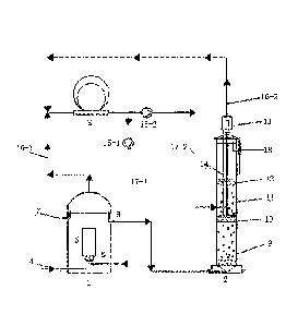
BRIEF DESCRIPTION OF THE DRAWING
FIG. 1 is a schematic structural diagram of a device for treating high-calcium
wastewater by
calcification blocking according to the present invention. In this figure, 1 -
alkalization tower, 2 - IC
anaerobic reactor, 3 - double membrane biogas tank, 4 - water inlet, 5 - gas-
lift pipe, 6 - gas
distributing device, 7 - overflow port, 8 - water pipe, 9- first anaerobic
reaction chamber, 10 -
primary three-phase separator, 11 - second anaerobic reaction chamber, 12 -
secondary three-phase
separator, 13 - gas-liquid separator, 14 - return pipe, 15-1 - first pressure
pump, 15-2 - second
pressure pump, 16-1 - first gas collecting tube, 16-2 - second gas collecting
tube, 17-1 - first gas
conveying tube, 17 -2- second gas conveying tube, and 18- anaerobic water
outlet pipe.
DETAILED DESCRIPTION
The present invention provides a method for treating high-calcium wastewater
by calcification
blocking, which includes the following steps:
mixing high-calcium wastewater, an alkalizing agent and a chelating agent, and
performing
alkalizing and conditioning pretreatment under a condition of stirring by
bubbling of a biogas, so as
to obtain pre-conditioned wastewater;
mixing the pre-conditioned wastewater with anaerobic granular sludge, and
performing
anaerobic reaction in a high hydraulic shear flow field formed by the biogas,
so as to generate the
biogas and calcium scale; and
refluxing a part of the biogas for the stiffing by bubbling of the biogas, and
refluxing the rest of
the biogas for forming the high hydraulic shear flow field.
In the present invention, the reagents are all commercially available products
well known to
those skilled in the art, unless otherwise specified.
The high-calcium wastewater is mixed with the alkalizing agent and the
chelating agent, and
alkalizing and conditioning pretreatment is performed under the condition of
stirring by bubbling of
the biogas, so as to obtain the pre-conditioned wastewater;
In the present invention, the concentration of calcium ions in the high-
calcium wastewater is
preferably 300-900 mg/L based on CaCO3.
In the present invention, the alkalizing agent preferably includes sodium
hydroxide, potassium
hydroxide, sodium carbonate, potassium carbonate, sodium bicarbonate or
potassium bicarbonate.
In the present invention, the dosage of the alkalizing agent is based on the
pH value of the
pre-conditioned wastewater, and the pH value of the pre-conditioned wastewater
is preferably
4
Date Regue/Date Received 2023-02-03
6.8-7.5, and more preferably 6.9-7.4. In the present invention, the alkalizing
agent is favorable for
dissolving carbon dioxide in the biogas to form alkalinity, and generating
soluble non-ionic calcium
compounds (in particular, chelates) with the calcium ions.
In the present invention, the chelating agent preferably includes one or more
of sodium
tripolyphosphate, potassium tripolyphosphate, sodium pyrophosphate, potassium
pyrophosphate,
sodium hexametaphosphate, potassium hexametaphosphate, sodium orthophosphate,
potassium
orthophosphate, sodium dihydrogen phosphate, potassium dihydrogen phosphate,
disodium
hydrogen phosphate and dipotassium hydrogen phosphate. In the present
invention, the dosage of
the chelating agent in the high-calcium wastewater is preferably 5-50 ppm, and
more preferably
10-45 ppm. In the present invention, the chelating agent can form soluble
chelates with calcium
ions, destroy salt crystals such as calcium carbonate and calcium phosphate to
form loose and
amorphous calcium scales, and reduce the calcification rate of the anaerobic
granular sludge.
In the present invention, the time for the alkalization conditioning
pretreatment is preferably
4-12 h, and more preferably 5-10 h. In the present invention, temperature for
the alkalization
conditioning pretreatment is preferably 18-35 C, and more preferably 20-33 C.
In the present
invention, the alkalization conditioning pretreatment is carried out under the
condition of stirring by
bubbling of the biogas. The present invention has no special limitation on the
rate of the stirring,
and a stirring rate well known to those skilled in the art can be used. In the
present invention, the
conversion of the calcium ions in the wastewater towards soluble non-ionic
calcium compounds is
accelerated through the alkalization conditioning pretreatment. In the present
invention, the stirring
by bubbling of the biogas is beneficial for forming biogas internal
circulation during the alkalization
conditioning pretreatment process, and promoting the rise of the wastewater,
which is beneficial for
the alkalization conditioning pretreatment process of the high-calcium
wastewater.
In the present invention, when the high-calcium wastewater is mixed with the
alkalizing agent
and the chelating agent, the method further includes adding a coagulant or
flocculating agent. In the
present invention, the coagulant preferably includes polyacrylamide and/or
chitosan; and the
coagulant is preferably used in a dosage of 5-20 ppm, and more preferably 10-
15 ppm. In the
present invention, the flocculating agent preferably includes polyaluminum
chloride and/or ferric
trichloride, and the dosage of the flocculating agent is preferably 10-50 ppm,
and more preferably
15-45 ppm. In the present invention, the use of the coagulant or the
flocculating agent is beneficial
for removing adhesive substances from the wastewater through air floatation
while promoting
calcium crystallization.
After the alkalization conditioning pretreatment, the alkalinity of the high-
calcium wastewater
is increased, calcium crystals are precipitated, and the calcium ion content
in the water body is
preliminarily reduced.
In the present invention, after the pre-conditioned wastewater is obtained,
the pre-conditioned
Date Regue/Date Received 2023-02-03
wastewater is mixed with the anaerobic granular sludge, and the anaerobic
reaction is carried out in
a high hydraulic shear flow field formed by the biogas, so as to generate the
biogas and calcium
scales.
In the present invention, the time for the anaerobic reaction is preferably 6-
24 h, and more
preferably 8-22 h. In the present invention, temperature for the anaerobic
reaction is preferably
25-35 C, and more preferably 27-33 C.
In the present invention, after the biogas is obtained, refluxing of a part of
the biogas is used for
the stirring by bubbling of the biogas in the alkalization conditioning
pretreatment, and refluxing of
the rest of the biogas is used for foiming a high hydraulic shear flow field
in an anaerobic reaction
environment. According to the present invention, the stirring by bubbling of
the biogas is carried
out by utilizing refluxing of a part of the biogas, so as to reinforce the
mixing under stifling, and the
alkalinity of the wastewater is improved by utilizing dissolution of carbon
dioxide in the biogas, so
that the conversion of calcium ions towards non-ionic states is facilitated.
In the present invention, the gas-liquid ratio of the refluxed biogas rate to
the pre-conditioned
wastewater in the anaerobic reaction is preferably (5-10):1, and more
preferably (6-9):1.
In the present invention, the pre-conditioned wastewater enters from the
bottom of the
anaerobic reactor and is mixed with the anaerobic granular sludge to convert
organic pollutants into
the biogas, such that it is difficult for the soluble non-ionic calcium
compounds generated by the
alkaline conditioning pretreatment of the wastewater to enter the inside of
the anaerobic granular
sludge and be intercepted and folin insoluble calcium scales. The rise of the
pre-conditioned
wastewater in the anaerobic reactor is realized through the gas lift function
of the biogas. The
biogas pumped into the anaerobic reaction environment forms biogas internal
circulation, and a
high hydraulic shear flow field is foimed at the bottom of the IC anaerobic
reactor, so that calcium
scales such as calcium carbonate, calcium phosphate and the like adsorbed on
the surface of the
anaerobic granular sludge are peeled off from the outer layer of the anaerobic
granular sludge,
calcium scales are facilitated to be discharged out of the anaerobic reactor
along with the
wastewater, and the anaerobic reactor is effectively prevented from being
blocked by calcium
scales.
The present invention also provides a device for use in the method for pre-
conditioning the
high-calcium wastewater by calcification blocking, which includes an
alkalization tower 1, an IC
anaerobic reactor 2 and a double membrane biogas tank 3, which are
sequentially communicated.
The device provided by the present invention includes an alkalization tower 1.
In the present
invention, the alkalization tower is a device containing a cavity; and in the
present invention, the
alkalization conditioning pretreatment is carried out on the high-calcium
wastewater in the cavity.
In the present invention, the bottom of the side wall of the tower body of the
alkalization tower
1 is provided with a water inlet 4 for introducing the high-calcium
wastewater.
6
Date Regue/Date Received 2023-02-03
In the present invention, the upper part of the side wall in the tower body of
the alkalization
tower 1 further includes an gas-lift pipe 5. The present invention has no
special limitation on the
structure of the gas-lift pipe 5, and an gas-lift pipe well known to those
skilled in the art can be
used. In the present invention, the gas-lift pipe 5 is favorable for
destroying the gas-liquid
equilibrium interface of biogas-wastewater in the alkalization conditioning
pretreatment, thereby
facilitating dissolution of carbon dioxide in the biogas to form carbonate,
and improving the
alkalinity of the wastewater.
In the present invention, a gas distributing device 6 is also arranged at the
lower part in the
tower body of the alkalization tower 1. The present invention has no special
limitation on the
structure of the gas distributing device 6, and a gas distributing device well
known to those skilled
in the art can be used. In the present invention, the gas distributing device
provides biogas bubbling
for the alkalization conditioning pretreatment, which is beneficial for
forming biogas internal
circulation, promoting the rise of the wastewater and facilitating the
alkalization conditioning
pretreatment process of the high-calcium wastewater. The biogas foims biogas
bubbling in the
alkalization tower 1 through the gas distributing device connected with a
first gas conveying tube
17-1, and then the rising biogas is discharged through an gas outlet
positioned at the top of the
alkalization tower 1, and is introduced into the double membrane biogas tank 3
through a first gas
collecting tube 16-1 for subsequent biogas recycling.
In the present invention, the upper end of the side wall of the alkalization
tower 1 is also
provided with an overflow port 7. The present invention has no special
limitation on the structure of
the overflow port 7, and an overflow port well known to those skilled in the
art can be used. In the
present invention, the overflow port 7 is beneficial for ensuring the amount
of the wastewater to be
subjected to alkalization conditioning in the alkalization tower, so as to
prevent incomplete
alkalization conditioning pretreatment caused by excessive wastewater, and to
prevent insufficient
calcification blocking of the high-calcium wastewater due to ineffective
alkalization conditioning
pretreatment.
In the present invention, the upper end of the side wall of the alkalization
tower 1 is also
provided with a water outlet. The water outlet is positioned below the
horizontal plane of the
overflow port 7. The water outlet is connected with the water pipe 8.
In the present invention, the chelating agent, the alkalizing agent, the
coagulant and the
flocculating agent are preferably mixed with the high-calcium wastewater
before entering the
alkalizing tower; or alternatively are pumped into the high-calcium wastewater
quantitatively in the
alkalizing tower. The present invention has no special limitation on the agent
pumping device in the
alkalization tower, as long as the agent pumping device can pump the added
agent.
The device provided by the present invention includes an IC anaerobic reactor
2 which is
communicated with the water outlet of the alkalization tower 1 through a water
inlet. In the present
7
Date Regue/Date Received 2023-02-03
invention, the water outlet of the alkalization tower 1 and the water inlet of
the anaerobic reactor 2
are connected through the water pipe 8. In the present invention, the
anaerobic reaction treatment on
the pre-conditioned wastewater is carried out in the IC anaerobic reactor 2.
In the present invention,
the water inlet of the IC anaerobic reactor 2 is arranged at the bottom of the
IC anaerobic reactor 2.
In the present invention, the IC anaerobic reactor includes a first anaerobic
reaction chamber 9
and a second anaerobic reaction chamber 11 from bottom to top. In the present
invention, the IC
anaerobic reactor includes the first anaerobic reaction chamber 9 provided at
the bottom of the IC
anaerobic reactor 2. In the present invention, the first anaerobic reaction
chamber contains
anaerobic sludge particles. The anaerobic sludge particles in the first
anaerobic reaction chamber
undergo an anaerobic reaction with the wastewater that has been subjected to
alkalization
preconditioning and enters into the first anaerobic reaction chamber from a
water inlet. The
anaerobic inlet water and the internal circulation mixed liquor in the first
anaerobic reaction
chamber 9 jointly form a local high hydraulic shear flow field to promote
calcium scales such as
calcium carbonate, calcium phosphate and the like adsorbed on the surface of
the anaerobic
granular sludge to be peeled off from the outer layer of the anaerobic
granular sludge, and thus the
organic pollutants in the inlet water are fully mixed with the anaerobic
granular sludge, and then
degraded and converted into the biogas.
In the present invention, the concentration of anaerobic granular sludge in
the second anaerobic
reaction chamber 11 is relatively low, and a part of organic matters not
degraded in the first
anaerobic reaction chamber 9 is converted into a small amount of the biogas.
The second anaerobic
reaction chamber 11 is filled with the anaerobic sludge particles, and the
refluxed biogas is input
into the second anaerobic reaction chamber 11 from the double membrane biogas
tank 3 through the
second gas conveying tube 17-2 to form a high hydraulic shear flow field, such
that the anaerobic
reaction occurs in the second anaerobic reaction chamber 11 and calcium scales
such as calcium
carbonate, calcium phosphate and the like adsorbed on the surface of the
anaerobic granular sludge
are promoted to be peeled off from the outer layer of the anaerobic granular
sludge and discharged
from the anaerobic reaction system under the action of the high hydraulic
shear flow field, thereby
effectively preventing calcification and hardening of the anaerobic system
during the treatment of
the high-calcium wastewater.
In the present invention, the bottom of the first anaerobic reaction chamber 9
and the bottom of
the second anaerobic reaction chamber 11 are respectively provided with gas
distributing devices.
The present invention has no special limitation on the gas distributing
devices, and gas distributing
devices well known to those skilled in the art can be used.
In the present invention, in the IC anaerobic reactor 2, a primary three-phase
separator 10 is
arranged between the first anaerobic reaction chamber 9 and the second
anaerobic reaction chamber
11. In the present invention, the primary three-phase separator 10 separates
the biogas in the first
8
Date Regue/Date Received 2023-02-03
anaerobic reaction chamber 9 from the lifted mixed liquor of muddy water,
traps the anaerobic
granular sludge in the first anaerobic reaction chamber 9, and guides the
biogas along with the
moisture out to a gas-liquid separator 13.
In the present invention, the IC anaerobic reactor includes an anaerobic water
outlet pipe 18
arranged at the upper end of the side wall of the IC anaerobic reactor 2. The
present invention has
no special limitation on the structure of the anaerobic water outlet pipe 18,
and an anaerobic water
outlet pipe well known to those skilled in the art can be used.
In the present invention, a secondary three-phase separator 12 is also
provided between the
second anaerobic reaction chamber 11 and the anaerobic outlet pipe 18. In the
present invention, the
secondary three-phase separator separates the biogas in the second anaerobic
reaction chamber 11
from the lifted mixed liquor of muddy water, traps the anaerobic granular
sludge in the second
anaerobic reaction chamber 11, and guides the biogas along with the moisture
out to the gas-liquid
separator 13.
In the present invention, the IC anaerobic reactor includes the gas-liquid
separator 13 arranged
at the top of the IC anaerobic reactor 2. In the present invention, the gas-
liquid separator 13 includes
a gas-liquid separation chamber and an gas-lift pipe arranged at the top of
the IC anaerobic reactor
2. The bottom of the gas-lift pipe is in contact with the upper end face of
the primary three-phase
separator 10. The top of the gas pipe penetrates through the top of the IC
anaerobic reactor 2 into
the gas-liquid separation chamber of the gas-liquid separator 13. In the
present invention, the
gas-liquid separator 13 separates the biogas from the primary three-phase
separator 10 and the
secondary three-phase separator 12 from the mixed liquor entrained and lifted
by its gas-lift action,
and the obtained mixed liquor returns to the bottom of the first anaerobic
reaction chamber 9
through the return pipe 14 due to density difference and gravity action.
In the present invention, the IC anaerobic reactor includes a return pipe 14
arranged in the
middle of the IC anaerobic reactor 2. In the present invention, the return
pipe 14 passes through the
second anaerobic reaction chamber 11 and the secondary three-phase separator
12 into the
gas-liquid separator 13 at the top of the IC anaerobic reactor. The bottom of
the return pipe 14 is in
contact with the upper end face of the primary three-phase separator 10. The
top of the return pipe
14 penetrates through the top of the IC anaerobic reactor 2 into the gas-
liquid separator 13. In the
present invention, the wastewater separated by the gas-liquid separator 13
returns to the first
anaerobic reaction chamber 9 through the return pipe 14 to be mixed with the
inlet water, so that the
concentration of the wastewater that has been subjected to alkalization
preconditioning can be
diluted; and the rising flow rate can be maintained when the amount of the
incoming wastewater is
insufficient.
The device provided by the present invention includes a double membrane biogas
tank 3. The
present invention has no special limitation on the structure of the double
membrane biogas tank 3,
9
Date Recue/Date Received 2023-02-03
and a double membrane biogas tank well known to those skilled in the art can
be used. In the
present invention, the double membrane biogas tank 3 has the functions of
storing the biogas and
outputting the biogas. In the present invention, when the double membrane
biogas tank 3 is used for
biogas storage, the capacity adjustment is realized by adjusting the air
pressure between the inner
membrane and the outer membrane in the double membrane biogas tank 3. When the
double
membrane biogas tank 3 is used for outputting the biogas, the flow regulation
of outputting the
biogas to the alkalization tower 1 and the IC anaerobic reactor 2 is realized
through a first pressure
pump 15-1 and a second pressure pump 15-2.
In the present invention, an gas outlet at the top end of the alkalization
tower 1 is connected
with an gas inlet of the double membrane biogas tank 3 through a first gas
collecting tube 16-1 to
form a gas collecting pipeline in the direction of the double membrane biogas
tank 3. Meanwhile,
an gas outlet at the top end of the IC anaerobic reactor is connected with the
gas inlet of the double
membrane biogas tank 3 through a second gas collecting tube 16-2 to form a gas
collecting pipeline
in the direction of the double membrane biogas tank 3. In the present
invention, the gas outlet of the
double membrane biogas tank 3 is connected with the gas inlet of the gas
distributing device 6 in
the alkalization tower 1 through a gas conveying tube 17-1. The gas outlet of
the double membrane
biogas tank 3 is connected with the gas inlet in the IC anaerobic reactor
through a gas conveying
tube 17-2. The gas inlet in the IC anaerobic reactor is arranged on the side
wall of the IC anaerobic
reactor 2 and leads into the second anaerobic reaction chamber 11.
In the present invention, the device for use in the method for treating the
high-calcium
wastewater by calcification blocking further includes a first pressure pump 15-
1 and a second
pressure pump 15-2 which are respectively positioned on the first gas
conveying tube 17-1 and the
second gas conveying tube 17-2. In the present invention, when the power for
the biogas bubbling
in the alkalization tower 1 or the biogas refluxing in the IC anaerobic
reactor is insufficient, gas is
blown via the first pressure pump 15-1 and the second pressure pump 15-2 to
forcibly form biogas
internal circulation in the alkalization tower 1 or the IC anaerobic reactor
2.
In order to further illustrate the present invention, the method for treating
the high-calcium
wastewater by calcification blocking and the device for implementing the
method according to the
present invention are described in detail below with reference to examples,
but they cannot be
understood as limiting the claimed scope of the present invention.
The high-calcium wastewater enters the alkalization tower 1 from the water
inlet pipe 4. The
high-calcium wastewater is mixed with the alkalizing agent and the chelating
agent. The pH of the
high-calcium wastewater is adjusted to 6.8-7.5. The biogas collected in the
double membrane
biogas tank 3 is introduced into the gas distributing device 6 of the
alkalization tower 1 under the
action of the pressure pump 15-1. Under the agitation action of the gas flow
of the biogas, the full
bubbling and mixing of the biogas with the original wastewater are
accelerated, and at the same
Date Regue/Date Received 2023-02-03
time, CO2 dissolution plus the high alkalinity formed by the action of the
alkalizing agent and the
chelating agent promote the precipitation of calcium crystals, so as to obtain
the pre-conditioned
wastewater.
The biogas in the alkalization tower 1 is conveyed into the double membrane
biogas tank 3
through the gas collecting tube 16-1. The pre-conditioned wastewater enters
the IC anaerobic
reactor 2 through the water pipe 8, and sequentially enters the first
anaerobic reaction chamber 9
and the second anaerobic reaction chamber 11 through the water distributing
device for
biodegradation. Most biodegradable organic matters are converted into the
biogas in the first
anaerobic reaction chamber 9 and the second anaerobic reaction chamber 11 to
serve as power for
realizing internal circulation of the lower mixed liquor and reinforcing
wastewater treatment. At the
same time, the generated biogas rises through the gas-lift pipe connecting the
primary three-phase
separator and the secondary three-phase separator. Due to the gas-lift action,
part of the muddy
water mixture enters the primary three-phase separator 10 of the first
anaerobic reaction chamber 9
together with the biogas. The biogas is separated and discharged from the gas-
lift pipe. The
obtained mixed liquor returns to the bottom of the first anaerobic reaction
chamber 9 through the
return pipe 14 due to density difference and gravity effect, and is fully
mixed with the inlet water
and the granular sludge, so as to realize internal circulation of the mixed
liquor of the whole system.
The rising water flow continues to enter the second anaerobic reaction chamber
11 for deep
degradation. The generated biogas enters the secondary three-phase separator
12 for collection, is
separated by the gas-liquid separator 13 and collected into the double
membrane biogas tank 3
through the gas collecting tube 16-2. The muddy water of the second anaerobic
reaction chamber 11
is subjected to solid-liquid separation in a mixed-liquor precipitation area,
and meanwhile, calcium
crystals generated by alkalization conditioning pretreatment settle in the
precipitation area, and the
supernatant overflows and is discharged through the anaerobic water outlet
pipe 18. The
precipitated granular sludge can automatically return to the second anaerobic
reaction chamber 11,
and the treatment of the high-calcium wastewater is completed, where calcium
scales and calcium
crystals are settled and exported in the precipitation area, and thus the IC
anaerobic reactor 2 does
not suffer from hardening of the anaerobic granular sludge and blocking of the
IC anaerobic reactor.
Example 1
Source and composition of high-calcium wastewater: a recycled paper making
enterprise which
had a daily average wastewater discharge of 1,000 tons, a wastewater COD
concentration of 4,000
mg/L, a calcium ion concentration of 300 mg/L, and a pH value of 5.6 of the
wastewater before
entering the system.
The wastewater treatment was conducted through a method for treating the high-
calcium
wastewater by calcification blocking, and the method includes the following
steps.
The device of the present invention was adopted to operate the method for
treating the
11
Date Regue/Date Received 2023-02-03
high-calcium wastewater by calcification blocking, where sodium hydroxide was
added into the
inlet water of the high-calcium wastewater to adjust the pH value to 6.8-7.5,
the chelating agent
sodium tripolyphosphate was added according to the content of 5-50 ppm in the
water body for
alkaline conditioning pretreatment; and the amount of refluxed biogas was
controlled according to a
gas-liquid ratio of (5-10):1 and the flow rate of the inlet water, so as to
obtain the wastewater that
had been subjected to alkalization preconditioning.
The obtained wastewater that had subjected to alkalization preconditioning was
introduced into
an IC anaerobic reactor for anaerobic treatment of the wastewater.
Comparative Example 1
Without the alkalization conditioning pretreatment step, the high-calcium
wastewater was
directly introduced into an IC anaerobic reactor for wastewater treatment, and
the other operations
were the same as those in Example 1.
Example 2
The concentration of calcium ions in the high-calcium wastewater was 600 mg/L,
and the rest
operations were the same as those in Example 1.
Comparative Example 2
The concentration of calcium ions in the high-calcium wastewater was 600 mg/L,
and the rest
operations were the same as those in Comparative Example 1.
Example 3
The concentration of calcium ions in the high-calcium wastewater was 900mg/L,
and the rest
operations were the same as those in Example 1.
Comparative Example 3
The concentration of calcium ions in the high-calcium wastewater was 900mg/L,
and the rest
operations were the same as those in Comparative Example 1.
Using a calcium ion rejection rate and the biological activity of granular
sludge as reference
standards for relieving calcification degree of anaerobic granular sludge, the
wastewater treatment
effects of Examples 1-3 and Comparative Examples 1-3 were tested. The test
method was as
follows:
(1) the calcium ion rejection rate was calculated based on the concentrations
of the inlet water
and outlet water of the anaerobic reactor, as shown in the following equation:
¨
r X TM
where, r was a calcium ion rejection rate in %;
On and Co ut were respectively calcium ion concentrations of the inlet water
and outlet water of
12
Date Regue/Date Received 2023-02-03
the IC anaerobic reactor respectively, and the unit was mgCa'/L.
(2) The biological activity of the granular sludge was measured according to
the gas production
rate of the IC anaerobic reactor, and the 'mit was m3 biogas/kg COD.
The test results are shown in Table 1.
Table 1 Wastewater Treatment Test Results of Examples 1-3 and Comparative
Examples 1-3
Cot/mg Ca21-/L r/% Biogas production (m3 biogas/kg
COD)
Example 1 235-255 14.5 0.41
Comparative
95-105 32.1 0.32
Example 1
Example 2 510-555 9.5 0.38
Comparative
395-425 33.1 0.29
Example 2
Example 3 805-835 7.5 0.30
Comparative
650-700 22.7 0.21
Example 3
As can be seen from Table 1, compared with the ordinary anaerobic treatment
process before
improvement in Comparative Examples 1-3, in the present invention after the
pretreatment
alkalization tower and the biogas circulation process are introduced, the
rejection rate of calcium
ions by the granular sludge is obviously reduced, and the biogas production is
obviously increased,
indicating that the method provided by the present invention can effectively
ensure the biological
activity of the anaerobic granular sludge and prevent the anaerobic granular
sludge from hardening
or even blocking the anaerobic system.
The above descriptions are merely preferred implementations of the present
invention. It should
be noted that a person of ordinary skill in the art may further make several
improvements and
modifications without departing from the principle of the present invention,
but such improvements
and modifications shall also be deemed as falling within the protection scope
of the present
invention.
13
Date Regue/Date Received 2023-02-03