Note: Descriptions are shown in the official language in which they were submitted.
CA 03081632 2020-05-04
1
Method and device for the torque measurement
in the drive train of a wind energy facility
The invention relates to a method for the torque measurement in a drive
train, preferably in a drive train of a wind energy facility. Furthermore, the
in-
vention relates to a device for the torque measurement in a drive train, pref-
erably in a drive train of a wind energy facility.
Methods for torque measurement in a drive train of a wind energy facility are
known in the state of the art. WO 2017/000 949 Al for example describes a
method which determines the torque acting upon the drive train on the basis
of a twisting. This method is based on the consideration that a shaft twists
due to the application of a torque and this twisting therefore represents a di-
rect measure for the applied torque. In order to determine the twisting, two
sensors which measure a rotation speed of the shaft are positioned at two dif-
ferent positions on the drive train. The sensors provide the rotation speeds
in
the form of frequencies as an output signal. The output signals of the two sen-
sors are superimposed, so that a third signal is generated, said third signal
be-
ing dependent on the first and the second rotation speed. The drive train is
twisted due to a change of the torque which acts upon the drive train. Given a
wind energy facility and a torque which is applied onto the rotor blades by
the
wind, the rotor mains shaft for example, on which one of the sensors is ar-
ranged, herein twists such that the output signal of the one sensor and hence
the third signal changes. The deformation of the rotor main shaft is propor-
tional to the torque which acts upon the shaft, so that one can derive the
torque by way of a comparison of the third signal with a reference value. The
torque which is determined in such a manner is mostly too inaccurate for a
closed-loop control (regulation) of the wind energy facility, for load
minimisa-
tion, for optimising the energy yield and/or for the active oscillation
damping
in wind energy facilities.
DE 10 2013 227 055 Al relates to a method for determining a rotation angle
position and a speed of a shaft of a drive train, wherein at least two sensors
are arranged on the shaft in the circumferential direction and detect a meas-
urement value which characterises the rotation. The rotation angle position is
20.04.20 - NE/SW/MT - lIbersetzung
Date Recue/Date Received 2020-05-04
CA 03081632 2020-05-04
2
determined from the measurement values, wherein a distance of the two sen-
sors is taken into account with this evaluation and the torque is determined
from the rotation angle.
In view of this state of the art, it is the object of the present invention to
sug-
gest a method which is comparatively inexpensive and which improves an ac-
curacy of torque measurements. Furthermore, the object of the invention is
to suggest a device for indeed carrying out this method.
This object is achieved by a method with the features of claim 1 as well as by
a
device according to the further independent claim. Advantageous further em-
bodiments result from the features of the dependent claims and of the em-
bodiment example.
The method according to the invention is suitable for torque measurement in
a drive train, in particular in a drive train in a wind energy facility. At
least two
incremental encoders are positioned at two different positions on at least one
shaft of the drive train, for example on a rotor main shaft of a wind energy
fa-
cility and each provide periodic rotation signals given a rotation movement of
the shaft. The rotation signals can herein be present for example as rectangu-
lar signals or as sine signals. The phases of the rotation signals are
evaluated
for determining a phase shift between the rotation signals of the two incre-
mental encoders. A torque of the shaft is determined from the phase shift.
The evaluated phase shift is corrected in dependence on a first zero-load
phase shift and using a stiffness factor K, wherein an in-situ calibration for
de-
termining the zero-load phase shift and the stiffness factor is carried out be-
fore and/or between the torque measurements.
Within the framework of the in-situ calibration, a first zero-load signal of
the
first incremental encoder and a second zero-load signal of the second incre-
mental encoder are measured over a first measuring time period. A tempo-
rally averaged zero-load phase shift is determined between the first zero-load
signal and the second zero-load signal. The wind energy facility is operated
below a nominal speed during the first measuring time period, wherein a gen-
erator torque is set to zero.
20.04.20 - NE/SW/MT - lIbersetzung
Date Recue/Date Received 2020-05-04
CA 03081632 2020-05-04
3
Furthermore, the in-situ calibration comprises a determining of the stiffness
factor K. To this end, a first nominal load signal of the first incremental en-
coder and a second nominal load signal of the second incremental encoder
are measured over a second measuring time period. A generator torque is
kept larger than zero at nominal load. A temporally averaged nominal load
phase shift is determined between the first nominal load signal and the sec-
ond nominal load signal. The stiffness factor K is determined in dependence
on the nominal load phase shift.
The suggested method for the torque measurement has the advantage that a
comparatively simple and inexpensive torque measurement in the drive train
can be carried out. Furthermore, the torque measurement is adequately accu-
rate due to the in-situ calibration. An adequate accuracy of the torque meas-
urement can be advantageous in particular for the regulation of wind energy
facilities and improve these. A wind energy facility regulation can be used
for
example for the load minimisation within the mechanical drive train, for the
optimisation of the energy yield by way of an improved MPP tracking (maxi-
mum power point tracking) in the part-load region, for the active oscillation
damping within the drive train or for a more accurate determining of the effi-
ciency.
The determined phase shift is preferably corrected by way of the subtraction
or addition of the zero-load phase shift. The determined phase shift can fur-
ther be corrected by way of multiplication by the stiffness factor K.
In order to measure the nominal load signals during the second measuring
time period, the wind energy facility is preferably operated at nominal load,
i.e. at a nominal speed. Herein, the rotor speed is preferably almost
constant,
which in particular is given at low fluctuations of the wind speed. The genera-
tor is connected to the rotor main shaft in a manner such that a rotation
movement of the rotor main shaft is transmitted onto the generator input
shaft. Typically, a gear is intermediately connected between the rotor main
shaft and the generator input shaft, so that the speeds of the rotor main
shaft
and of the generator input shaft can be different. The generator torque typi-
cally corresponds to an air gap torque, i.e. to an internal generator torque
be-
tween the stator and the rotor of the generator.
20.04.20 - NE/SW/MT - lIbersetzung
Date Recue/Date Received 2020-05-04
CA 03081632 2020-05-04
4
In one embodiment, the generator can be connectable to the gear output
shaft by way of a coupling, so that the generator can be for example decou-
pled during the first measuring time period and the generator torque can set
in from zero.
In a further embodiment, the generator torque can be kept essentially con-
stant and recorded by way of a wind energy facility control system or regula-
tion during the second measuring time period. To this end, the rotor speed
can be regulated to a facility nominal speed via the rotor blade adjustment,
also called pitch regulation. The pitch regulation can have sluggish
characteris-
tics, so that the rotor speed due to the dynamic braking and acceleration
torque components fluctuates about the facility nominal speed in a range be-
tween 10% and can cause a fluctuation in the generator torque. The genera-
tor torque can therefore be averaged over the second measuring time period.
The preferably averaged generator torque can be divided by the phase shift
which is averaged over the second measuring time period, for determining
the stiffness factor K.
The generator torque can be determined numerically by a converter from
generator parameters, i.e. air gap torque and the generator speed. To this
end, for example a generator speed signal can be made available to the con-
verter by one of the incremental encoders. A generator speed signal can also
be transferred to the converter from a further incremental encoder. Herein,
the further incremental encoder is preferably arranged as close as possible to
the generator, preferably at the generator end of the output side.
In one embodiment, the first and/or the second measuring time period is at
least 2 minutes, preferably at least 4 minutes, particularly preferably at
least 5
minutes. The first and/or the second measuring time period is usually maxi-
mally 20 minutes, preferably maximally 15 minutes, particularly preferably
maximally 10 minutes long. The zero-load phase shift and/or the stiffness fac-
tor K can therefore be determined in a comparatively short time. Further-
more, an adequate accuracy of the zero-load phase shift and/or of the stiff-
ness factor can be achieved since several values for the zero-load phase shift
and/or for the stiffness factor K can be determined over the respective meas-
uring time period and be averaged.
20.04.20 - NE/SW/MT - lIbersetzung
Date Recue/Date Received 2020-05-04
CA 03081632 2020-05-04
In one embodiment, the wind energy facility can be braked for example from
a wind energy normal operation, for reaching a speed below the nominal
speed for determining the zero-load phase shift during the in-situ
calibration.
The measurement values of the two incremental encoders can herein be eval-
5 uated in a range of predefined speeds, for example between 1 and 5 rpm,
even more preferred between 1 and 3 rpm, for determining the zero-load
phase shift. In normal operation, the rotor is typically rotated into the wind
such that the wind drives the rotor, so that a positive drive torque acts upon
the rotor main shaft and preferably moves the rotor main shaft at a nominal
speed. The rotor blades can be brought into the feathering position via a
pitch
adjustment of the rotor blades for braking the wind energy facility, so that
the
wind can no longer exert a positive drive torque onto the rotor main shaft via
the rotor. Typically, the rotor speed further decreases by way of an aerody-
namic braking moment. The generator can herein be switched off, for exam-
ple by way of decoupling the gear output shaft and the generator input shaft,
so that a generator moment is equal to zero. Alternatively, the converter can
also be disconnected.
In a further embodiment, the wind energy facility can also be started up from
a switched-off state for achieving a speed below the normal speed. Herein,
the measurement values of the two incremental encoders can be evaluated in
a range of predefined speeds, preferably between 1 and 5 rpm, even more
preferably between 1 and 3 rpm, for determining the zero-load phase shift.
On starting up the wind energy facility, the rotor blades are usually moved
from a feathering position in the direction of a nominal position in a very
slow
manner, for example by way of twisting the rotor blades by about 10 per mi-
nute. Acceleration moments can be reduced by way of a slow adjustment of
the rotor blades from the feathering position into the nominal position. The
generator can preferably also be switched off on starting up the wind energy
facility, so that the generator torque is preferably equal to zero.
One can envisage determining an averaged zero-phase shift on starting up
and on braking the wind energy facility. To this end, the zero-load phase
shift
which is determined after the braking of the wind energy facility and the zero-
load phase shift which is determined after starting up the facility can be
20.04.20 - NE/SW/MT - Ubersetzung
Date Recue/Date Received 2020-05-04
CA 03081632 2020-05-04
6
averaged. This can have the advantage that the zero-load shift has a higher
accuracy. This in turn can have an effect on the accuracy of the torque meas-
urement values during the torque measurements since, as already explained
above, the torque measurement values are corrected by the zero-load shift.
Furthermore, it can be advantageous to start up the wind energy facility be-
fore an in-situ calibration and to operate it over a certain time period, for
ex-
ample at least 30 minutes, without torque measurements, so that the drive
train of the wind energy facility warms up and has reached its nominal tem-
perature.
In one embodiment, the incremental encoder can be arranged on two differ-
ent shafts. The shafts can be coupled to one another by a gear. The transmis-
sion ratio of the gear is preferably constant. Typically, one of the
incremental
encoders, hereinafter denoted as the first incremental encoder, is arranged
on the rotor main shaft of the wind energy facility. Particularly preferably,
the
first incremental encoder is arranged close to the rotor. Herein, the rotor
main shaft can in particular be the gear input shaft. Typically, the other of
the
incremental encoders, hereinafter denoted as the second incremental en-
coder, is arranged on a gear output shaft. Alternatively, the second incremen-
tal encoder can likewise be arranged on the rotor main shaft. The second in-
cremental encoder is preferably arranged at a distance to the first incremen-
tal encoder, wherein the distance is also dependent on the dimensions of the
shaft. It can be for example between 50 cm and 300 cm. This has the ad-
vantage that the accuracy for detecting the torque is improved. On determin-
ing the stiffness factor K, preferably the transmission ratio of the gear is
to be
taken into account. In particular, given an arrangement of the first and the
second incremental encoder on the rotor main shaft, the determined torque
can be multiplied by the transmission ratio of the gear.
In an exemplary embodiment, the incremental encoders can be based on
known optical, inductive or magnetic measuring principles. Such incremental
encoders typically comprise an encoder and an encoder disc which are very
robust with regard to static and dynamic displacements between the encoder
and the encoder disc. Measuring errors or sensor failures can thus be reduced
or avoided. The encoder disc can also be designed as an encoder tape (sensor
20.04.20 - NE/SW/MT - lIbersetzung
Date Recue/Date Received 2020-05-04
CA 03081632 2020-05-04
7
tape) or an encoder ring, in particular given the application on a shaft.
In a further embodiment, the incremental encoder can have a resolution of at
least four impulses, preferably at least 16 impulses and/or maximal 16384 im-
pulses, particularly preferably maximally 4096 impulses per shaft revolution.
This has the advantage that standard incremental encoders can be used, said
standard incremental encoders being comparatively inexpensive compared to
high-resolution incremental encoders with resolutions of more than 16384
impulses per shaft revolution. Furthermore, standard incremental encoders
have the advantage that they are comparatively robust with regard to impacts
and load changes. Preferably, the selection of the impulses upon the encoder
discs or encoder rings is such that a uniform, i.e. gapless distribution of
the
impulses results over the respective shaft periphery. In particular, this is
ad-
vantageous if the incremental encoders are arranged at positions at which the
shaft diameters differ. The phases of the incremental encoders can be com-
pared in a simpler manner by way of a uniform impulse distribution and a
change of the phase shift is comparatively simple to determine.
The impulse number per shaft revolution of the two incremental encoders can
be designed identically in one embodiment. The impulse number can also be
dependent on the installation location. The impulse numbers of the incremen-
tal encoders can also differ from one another by way of an integer multiple.
Herein, the impulse number per shaft revolution of the incremental encoder
on a generator input shaft can in particular be smaller than the impulse num-
ber per shaft revolution of the incremental encoder on the rotor main shaft,
since the rotor main shaft is typically designed to be significantly thicker.
An
incremental encoder on the rotor main shaft accordingly preferably offers at
least 1000 impulses per revolution, whereas an incremental encoder on the
generator shaft which mostly has a smaller circumference has lower impulse
numbers. Preferably, the signals of the two incremental encoders are
matched to one another in a manner such that the impulses are produced
synchronously and a synchronous pulse pattern arises. The gear transmission
can herein be included in the calculation.
In a further embodiment, the first and/or the second incremental encoder,
preferably before a torque measurement, can be adjusted in a manner such
20.04.20 - NE/SW/MT - lIbersetzung
Date Recue/Date Received 2020-05-04
CA 03081632 2020-05-04
8
that the measurement signals of the incremental encoders have a phase shift
with a predefined value, preferably of 900, if the wind energy facility is
oper-
ated below a nominal speed and a generator torque is equal to zero, wherein
the first and/or the second incremental encoders are adjusted after their ar-
rangement if the desired value has not been reached. To this end, the first
and/or the second incremental encoders can be adjusted for example by way
of an electromechanical adjustment device. A phase shift of 90 is typically
ad-
vantageous since in such a manner an available measuring region can be di-
vided in equal parts onto positive and negative shaft moments.
Furthermore, the present invention relates to a device for the torque meas-
urement in the drive train of a wind energy facility, comprising at least two
in-
cremental encoders which are positioned at different positions on at least one
shaft of the drive train, and an evaluation device which is connected to the
in-
cremental encoders. The evaluation device is configured to determine a phase
shift from the measurement signals of the incremental encoders and to deter-
mine a torque of the shaft from the phase shift. Furthermore, the evaluation
device is configured to correct the phase shift in dependence on, preferably
by way of addition or subtraction of, a zero-load phase shift and using a
stiff-
ness factor K, preferably by multiplication by the stiffness factor K, and to
carry out an in-situ calibration for determining the zero-load phase shift and
stiffness factor K before and/or between the torque evaluations.
The evaluation device for carrying out the in-situ calibration is configured
to
measure a first zero-load signal of the first incremental encoder and a second
zero-load signal of the second incremental encoder over a first measuring
time period and to determine a temporally averaged zero-load phase shift be-
tween the first zero-load signal and the second zero-load signal, wherein the
wind energy facility is operated below the nominal speed and a generator
torque is equal to zero during the first measuring time period. The evaluation
device is further configured to measure a first nominal load signal of the
first
incremental encoder and a second nominal load signal of the second incre-
mental encoder over a second measuring time period and to determine a
temporally averaged nominal load phase shift between the first nominal load
signal and the second nominal load signal and to determine the stiffness
20.04.20 - NE/SW/MT - Ubersetzung
Date Recue/Date Received 2020-05-04
CA 03081632 2020-05-04
9
factor K in dependence on the nominal load phase shift, wherein the wind en-
ergy facility during the second measuring time period is operated at nominal
speed and the generator torque is kept larger than zero.
The device according to the invention can be integrated into existing drive
trains in a comparatively inexpensive and simple manner. Furthermore, the
advantageous methods for torque measurement which have been described
above can advantageously be carried by way of the device.
In one embodiment, the evaluation device can comprise a logic circuit for de-
termining the phase shift between the first and the second incremental en-
coder, for example an AND logic unit or an OR logic unit, a correlator or a
phase locked loop (PLL).
In one embodiment, the evaluation device can comprise an analysing unit, for
example a cross-correlator or a phase measuring element, for determining the
mechanical angle twist between the two incremental encoders and therefore
the torque.
In one embodiment, the evaluation device can comprise a flank-controlled
timer. Output signals can be digitally measured in a relative impulse time
inte-
gral, i.e. in a pulse-pause ratio, by way of the flank-controlled timer.
Herein,
the timer typically starts with a rising flank, stops with a dropping flank
and is
subsequently set back. The impulse period can therefore be measured on a
time basis of an integrated oscillator (internal clock generator). The period
du-
ration of the impulse sequences can serve as a reference value and can like-
wise be determined via a timer or impulse counter.
In a further embodiment, the evaluation device can be connected to the in-
cremental encoders via an electric lead connection.
In one possible embodiment, the device for the torque measurement can
comprise the aforementioned electromechanical adjusting device for set-
ting/adjusting a phase shift between the first and the second incremental en-
coder. The electromechanical adjusting device can preferably be formed on at
least one of the incremental encoders. The electromechanical adjusting de-
vice can comprise for example a play-free, electromotoric linear drive, for
20.04.20 - NE/SW/MT - lIbersetzung
Date Recue/Date Received 2020-05-04
CA 03081632 2020-05-04
example a spindle or a cam drive along the shaft contour. The at least one in-
cremental encoder can be moved in its position relative to the shaft, prefera-
bly in the tangential direction to the shaft and/or along the periphery of the
shaft, by way of the adjusting device. The incremental encoders can be ad-
5 justed automatically or manually by touch. Preferably, the incremental
encod-
ers are adjusted whilst the wind energy facility is not subjected to any exter-
nal torques and the rotor blades are in the feathering position. The at least
one incremental encoder can be adjusted in a mechanical manner radially or
along an outer contour of the shaft, on which the respective incremental en-
10 coder is arranged, in a manner such the complete theoretic measuring
range
is run through for the pulse-pause ratio. Subsequently, the incremental en-
coder or encoders can be displaced in such manner until the current measur-
ing signal for the pulse-pause ratio corresponds to the average with regard to
the minimal and the maximal pulse-pause ratio. The adjusting of pulse-pause
ratio can be repeated arbitrarily often on operation. The pulse-pause ratios
of
the incremental encoders are preferably matched to one another before the
in-situ calibration and before the torque measurement.
The further features which have been explained in the present application
with reference to the method can also be features of the device. Vice-versa,
features which have been explained in the present application with reference
to the device can also relate to the method.
Embodiment examples of the invention are hereinafter described by way of
figures.
There are shown in:
Fig. la a drive train of a wind energy facility in a schematic
representation,
Fig. lb an evaluation device of the wind energy facility of Fig. la,
Fig. 2 rotation signals of a first incremental encoder and of a
second incre-
mental encoder and a signal of a logic evaluation given rotation
without load,
Fig. 3 rotation signals of the first incremental encoder and of the second
20.04.20 - NE/SW/MT - lIbersetzung
Date Recue/Date Received 2020-05-04
CA 03081632 2020-05-04
11
incremental encoder and the signal of a logic evaluation given a ro-
tation under load of a positively defined torque,
Fig. 4 rotation signals of the first incremental encoder and of the
second
incremental encoder and the signal of a logic evaluation given a ro-
tation under load of a negatively defined torque,
Fig. 5 an adjusting device for adjusting at least one of the two
incremental
encoders.
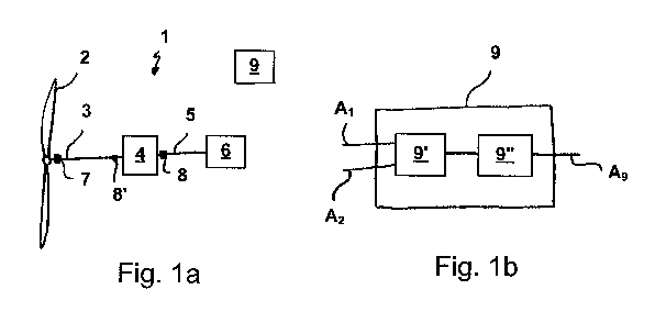
A drive train 1 of a wind energy facility is schematically represented in
Figure
la. A rotor 2 is arranged on a rotor main shaft 3. The rotor main shaft 3 is
an
input shaft of a gear 4. The gear 4 comprises a gear output shaft 5 which as a
generator input shaft is simultaneously connected to a generator 6. A wind
force which acts upon the rotor 2 rotates the rotor and thus drives the rotor
main shaft 3. The gear 4 steps up a slow rotation movement of the rotor main
shaft 3 into a quicker rotating movement of the gear output shaft 5 for the
generation of electricity in the generator 6. A first incremental encoder 7 is
ar-
ranged on the rotor main shaft 3. A distance between the rotor 2 and the first
incremental encoder 7 is smaller than a distance between the first incremen-
tal encoder and the gear 4. A second incremental encoder 8 is arranged on
the gear output shaft 5. The second incremental encoder 8 can also be ar-
ranged on the rotor main shaft 3, for example at a position 8'. The position
8'
has a smaller distance to the gear 4 than to the rotor 2 and both incremental
encoders in this case should be arranged at the greatest possible distance.
The incremental encoders 7 and 8 are connected to an evaluation device 9
(the connection is not represented in Figure 1 for a better overview). The in-
cremental encoders 7 and 8 provide output signals in the form of periodic ro-
tation signals. These rotation signals are transferred to the evaluation
device 9
via an electric lead connection.
Given normal operation of the wind energy facility, the rotor 2 is driven in
ac-
cordance with the wind strength and wind direction, so that different torques
which change with time act upon the rotor main shaft 3. In order to be able to
regulate the wind energy facility in a manner adapted to this, the respective
torque M (t) is required. The necessary torque measurement is based on a
20.04.20 - NE/SW/MT - lIbersetzung
Date Recue/Date Received 2020-05-04
CA 03081632 2020-05-04
12
direct evaluation of the relative twist angle between the two incremental en-
coders 7, 8. The mechanical angle twist between both encoders leads to a
phase shift of the encoder output signals and on superimposing the output
signals leads to a measurement signal At xt,meas with a changing pulse-pause
ra-
tio (in the case of rectangular signals of the incremental encoder) as a
direct
measure for this twisting and therefore for the effective torque (is explained
further below in more detail).
Figure lb shows the evaluation device 9 of Figure la. The evaluation device
comprises a superposition or logic circuit 9' which links the output signals
of
the incremental encoders 7, 8 to one another as measurement signals Ai and
A2. This logic circuit is designed for example as an AND logic unit. An output
signal of the logic circuit 9' is led further to an analysing unit 9" which
deter-
mines a mechanical angle twist between the two incremental encoders and
determines the torque therefrom. An output signal A9 of the evaluation de-
vice 9 is forwarded to the wind energy facility regulation.
Figure 2 shows measurement signals or rotation signals Ai and A2 of the two
incremental encoders 7, 8 on rotating without a load. The rotation signal Ai
of
the first incremental encoder 7 is represented in a diagram 10 and the rota-
tion signal A2 of the second incremental encoder 8 is represented in a diagram
20. The rotation signal Ai has an impulse amplitude 11 or Timp with a pulse-
pause ratio or duty cycle of 50/50. Herein, the impulse duration Thigh 12 is
just
as long as the pause time Tiow 13.
The impulse period is Timp = 60/nx (s), wherein x is the number of the
impulses
per revolution and n the shaft speed in r.p.m. The duty cycle is
TV((n ¨1)T, nT) = Thigh/(Thigh + Tiow) = 0.5.
The rotation signal A2 has an impulse period 21 which corresponds to the im-
pulse period 11 and likewise has a pulse-pause ratio of 50%. Herein, the pulse
duration 22 is just as long as the pause time 23. Furthermore, the pulse dura-
tion 22 corresponds to the pulse duration 12 and therefore also the pause
time 23 to the pause time 13. The rotation signal A2 is shifted with respect
to
the rotation signal Ai by a quarter of the period 21 or 11. This corresponds
to
a rotation angle of A
¨(Psignal = 90 .
20.04.20 ¨ NE/SW/MT ¨ Ilbersetzung
Date Recue/Date Received 2020-05-04
CA 03081632 2020-05-04
13
The measurement signals Ai and A2 are transferred to the evaluation device 9.
The measurement signals Ai and A2 are superimposed in the evaluation de-
vice 9, here comprising an AND logic unit 9'. The AND logic unit 9' thereupon
provides an output signal Abo, which is represented in a diagram 30 and
which has an impulse period 31 which corresponds to the impulse period 11
and 21. A pulse duration 32 herein corresponds to a quarter of the impulse
period 31, whereas a pause time 33 consequently corresponds to three-quar-
ters of the impulse period 31 (pulse-pause ratio 25%).
In order to achieve the aforementioned phase difference or phase shift of
preferably half an impulse period (with the pulse-pause ratio of 50% this cor-
responds to a phase shift of 90%) for the impulse signals of the two incremen-
tal encoders 7, 8 in the non-loaded state, a position adjustment between the
encoders is carried out since such a relative adjustment of the two incremen-
tal encoders 7, 8 cannot be reliably ensured during the assembly.
In order to adjust the position, the incremental encoders 7, 8 are adjusted by
way of an adjusting device in a manner such that the desired pulse-pause ra-
tio is achieved. To this end, one of the two encoders, i.e. the incremental en-
coder 7 is automatically or manually adjusted along a tangential path or one
which is adapted to the shaft contour, for example along a threaded rod or
spindle. Herein, it can move over the complete theoretical measuring region
during the adjusting. The pulse-pause ratio of 50% is specified by way of ex-
ample in the description, and any arbitrary pulse-pause ratio can be set, as
long as a conclusive evaluation of the signals is achieved.
In a further diagram 40, the output signal Abo, is represented in the extreme
positions Amin and Amax during the adjustment of the incremental encoders 7,
8 on moving over the complete theoretical measuring region. The dashed line
represents the output signal Amin and the unbroken line represents the output
signal Amax and herewith the limit of the adjustment.
After the previously described position adjustment, an in-situ calibration
method is carried out, in order to determine a zero-load phase shift or a zero-
point adjustment of the torque measuring device and a stiffness factor K
which takes into account an amplification factor or a gradient of the torque
20.04.20 - NE/SW/MT - Ubersetzung
Date Recue/Date Received 2020-05-04
CA 03081632 2020-05-04
14
measurement characteristic line of the drive train or a stiffness of the drive
train.
Before a calibration of the torque measuring device, the drive train of the
wind energy facility should have reached its nominal operating temperature.
This can be achieved e.g. by an adequately long operation of the wind energy
facility without the use of the torque measuring device. This can be carried
out without any restrictions since the additional torque sensorics, although
improving the facility behaviour, however are not absolutely necessary for the
operation.
In order to determine the zero-load phase shift, the wind energy facility is
brought into the idling region, i.e. into non-productive operation, via the
facili-
ty's control system, given operating conditions below the nominal speed, pref-
erably with weak wind condition. The braking of the facility into the idling
speed region can be carried out actively via the pitch adjustment of the rotor
blades. In this operational region, the facility is taken off the mains, i.e.
the
generator is not "subjected to current" and does not therefore develop a
torque Mgen.(t)=0, wherein this state is a necessary constraint. The blades of
the facility are then situated completely in the feathering position, at which
the pitch angle is roughly 90 . The rotor therefore no longer develops a posi-
tive drive torque, in contrast an aerodynamic braking moment Mrot.(t)-0 is ac-
tive, but this becomes exponentially smaller with a reducing speed.
After switching off the generator, the measurement values which are continu-
ously provided by the torque measuring device are recorded over the speed in
the range of very small speeds (between 3 and 1 rpm). In the evaluation de-
vice 9, the recorded measurement values are superimposed and a temporally
averaged zero-load phase shift A(t)brake between the output signal of the
first incremental encoder 7 and of the second incremental encoder 8 is deter-
mined for determining the zero point of the torque measuring device. The de-
termined zero-load phase shift is stored in the evaluation unit as a zero-
point
of the torque measuring device.
This measurement can also be repeated on starting up the facility given weak
wind and in idling operation for determining a zero-load phase shift A(t)high
,
20.04.20 - NE/SW/MT - Ubersetzung
Date Recue/Date Received 2020-05-04
CA 03081632 2020-05-04
likewise given a switched-off generator, wherein it is preferably carried out
in
the same rotor speed range (1-3 rpm). The blades are moved very slowly
1 /mm n out of the feathering position in the direction of the nominal
position
by way of the control system, in order to minimise the influence of accelera-
5 tion moments Mrot.(t)-0. The average of the averaged measurement values
of
the two trials (course of braking, starting up) is then formed
Azem = (A(t)brake + A(t)high) /2
and the zero-load phase shift or the zero point of the torque measurement
characteristic line which is represented by this is accordingly adapted and is
10 stored in the evaluation device.
For an exact measurement of the zero-load phase shift, it is advantageous for
both trials to be carried out in a directly subsequent manner. These trials
may
be repeated several times, as appropriate.
The determining of the stiffness factor K or of the reinforcement factor or
the
15 gradient of the torque measurement characteristic line of the torque
measur-
ing device is described hereinafter. This determining is preferably carried
out
in full-load operation, i.e. in the nominal operation of the facility, in
order to
obtain an accurate a measurement as possible over the complete torque
measuring range. In this operating region, the generator torque is kept con-
stant by the facility control system / facility regulation. The rotor speed is
ac-
tively regulated to the facility nominal speed via the rotor blade adjustment
(pitch). However, due to the relatively sluggish characteristics of the pitch
reg-
ulation, the rotor speed fluctuates in a range of as a rule 10% about the
nominal speed, so that dynamic braking and acceleration torque components
could upset the calibration of the torque measuring device. For this reason, a
longer measuring time period of several minutes, preferably up to maximally
10 minutes, is selected. During this measuring time period, the generator
torque should not change, i.e. the facility must operate in its nominal power
region during the complete measuring time period.
The generator torque corresponds to the air gap moment and this cannot be
detected by measuring technology in a direct manner, but is determined
20.04.20 - NE/SW/MT - lIbersetzung
Date Recue/Date Received 2020-05-04
CA 03081632 2020-05-04
16
numerically from the measured electrical characteristic variables and the gen-
erator parameters by the converter which is contained in the wind energy fa-
cilities, and is "communicated" to the facility control as signal/information.
As
is standard, for this the converter requires a generator rotor position signal
or
at least a generator rotor speed signal. This signal can be provided by one of
the incremental encoders 7, 8 or be provided by a standard encoder on the
generator.
The torque measuring device with the evaluation device 9 according to Fig. lb
and with an evaluation according to Fig. 2 provides measurement signals with
respect to a phase shift Acp between the two encoder signals given nominal
operation. The temporal average of the measurement signals of the torque
measuring device which specify the phase shifts, and the values of the certain
generator torque result in the stiffness factor
K = 111 /Ay/
by way of which hence the second necessary characteristic line point is given
for determining the torque measurement characteristic line, this point corre-
sponding to the wind energy facility nominal moment. This measurement
may, where necessary, be repeated arbitrarily often. In this case too, the
facil-
ity should have reached its nominal operating temperature. Optionally, the
determining of this value of the characteristic line can also be carried out
be-
fore determining the zero point.
The output signals or rotation signals Ai' and A2' of the two incremental en-
coders 7, 8 in normal measuring operation under the load of the wind energy
facility given a positive torque direction are represented in Figure 3. The
rota-
tion signals Ai' of the first incremental encoder 7 are specified in the upper
di-
agram 10'. The rotation signals A2' of the second incremental encoder 8 are
represented in the middle diagram 20'. In the second measuring time period,
the first incremental encoder 7 provides a rotation signal Ai' with an impulse
period 11' and with a pulse pause ratio of 50/50. Herein, the pulse duration
12' is just as long as the pause time 13'. The rotation signal A2' has an
impulse
period 21' which corresponds to the impulse period 11' and likewise has a
pulse-pause ratio of 50%. Furthermore, the pulse duration 22' corresponds to
the pulse duration 12' and therefore the pause time 23' to the pause time 13'.
20.04.20 - NE/SW/MT - Ubersetzung
Date Recue/Date Received 2020-05-04
CA 03081632 2020-05-04
17
The signal A2 according to Fig. 2 is represented in a dotted manner. The rota-
tion signal A2' leads the rotation signal Ai' by 15% of the impulse period 21
or
11. This corresponds to a rotation angle A(Psignal of 54 .
The output signals Ai' and A2' are superimposed in the AND logic which pro-
vides an output signal Alogic' with an impulse period 31', wherein here too
the
signal Alogic. according to Fig. 2 is represented in a dotted manner. The
pulse
duration 32' results with
A((n ¨1)T, nT) = Thigh/(Thigh + Tiow) = 0.35
i.e. 35% of the impulse period 31'. The output signal Alogi,' thus contains a
phase shift which results under load from the torque which is exerted upon
the rotor, as well as a phase shift which already prevails during a zero-load
op-
eration of the wind energy facility. The twist angle of the shaft Acpshaft
which is
caused by the load torque can be determined from the output signal Alogi,'
with the variables according to Fig. 2 by
A(Pshaft = (A((n ¨1)T, nT) ¨ 0.25) / 0.25. 90 /x = 36 /x
wherein x is the number of impulses per revolution. The torque can be deter-
mined from the torque characteristic line in dependence on the phase shift.
Rotation signals Ai" and A2" of the two incremental encoders 7, 8 in measur-
ing operation under load with a negative torque direction are represented in
Figure 4. The torque which acts upon the rotor main shaft corresponds to the
torque of Figure 3, but in Figure 4, as mentioned, is defined as negatively ro-
tating. The rotation signal Al" of the first incremental encoder 7 which corre-
sponds to the output signal or rotation signal Ai' is represented in the
diagram
10" and the rotation signal A2" of the second incremental encoder 8 is speci-
fied in diagram 20". The rotation signal A2" corresponds to the rotation
signal
A2' but is displaced oppositely to A2'. The time difference between the
signals
Ai" and A2" is AT = 0.35 Timp which corresponds to an angle A
¨(Psignai of 126 .
The output signals Ai" and A2" are superimposed in the AND logic which pro-
vides an output signal Alogi,' with an impulse period 31", wherein here too
the
signal Alogic. according to Fig. 2 is represented in a dotted manner. The
pulse
duration 32" results by
A((n ¨ 1)T, nT) = Thigh/(Thigh + Tiow) = 0.15
i.e. 15% of the impulse period 31". The pulse duration 32" is herein 15% of
20.04.20 - NE/SW/MT - Ilbersetzung
Date Recue/Date Received 2020-05-04
CA 03081632 2020-05-04
18
the impulse period 31". The output signal Abo," represents a phase shift
which results from the torque under load said torque being applied onto the
rotor, as well as a phase shift which also prevails during a zero-load
operation
of the wind energy facility. The twist angle of the shaft _Acpshaft which is
caused
by the load torque can be determined from the output signal Alogic' with the
variables according to Fig. 2 by
A(pshaft = (A((n ¨ 1)T, nT) ¨ 0.25) / 0.25 = 90 /x = -36 /x
wherein x is the number of impulses per revolution.
In order to measure the torque of the rotor main shaft of the wind energy fa-
cility 1, arbitrary output signals Ameasl and Ameas2 of the two incremental en-
coders are evaluated as is explained with Fig 3 and Fig. 4. Herein, the
rotation
signals of the incremental encoders 7, 8 are superimposed by the AND logic
circuit which provides a signal Ameaslog which represents the phase shift be-
tween the two rotation signals. In order to determine a momentary torque,
the signal of the zero-point evaluation A,0 is added to this current measure-
ment signal Ameaslog and the result is multiplied by the stiffness factor K:
M(t) = Ameaslog (t) * K ''zero* K.
The torque signal is used for example for the regulation of the wind energy fa-
cility.
Figure 5 shows an adjusting device 50 for adjusting an incremental encoder 51
relative to a shaft 52. An encoder disc or an encoder tape is fixedly
connected
to the shaft 52. The incremental encoder 51 comprises a sensor 51' for scan-
ning the encoder disc or the encoder tape. The incremental encoder 51 can
scan the encoder disc for example in a photoelectrical or magnetic manner.
Toothed wheels can also be used as encoder discs.
The adjusting device 50 is represented in Figure 5(1), whereas a cross section
through the shaft 52 and the arrangement of the adjusting device 50 relative
to the shaft 52 is shown in Figure 5 (1). The adjusting device 50 comprises a
linear drive 53 with a spindle 53', on which a slide 54 is arranged. The incre-
mental encoder sensor 51' is fastened to the slide. Furthermore, the adjusting
device comprises two guide rails 55, along which the slide is movable. The
spindle 53' of the linear drive 53 can be driven by an electric drive 56 in a
20.04.20 - NE/SW/MT - Ubersetzung
Date Recue/Date Received 2020-05-04
CA 03081632 2020-05-04
19
manner such that the slide is displaceable along the spindle in a direction
Ri.
In Figure 5 (2) it is represented that the adjusting device 50 is preferably
ar-
ranged in a manner such that the direction Ri runs tangentially to the shaft
52, so that the incremental encoder sensor 51 is adjustable tangentially to
the
shaft 52. Furthermore, the slide 54 can be rotated about the spindle 53' so
that an adjustment of the sensor 51' along the direction R2, adapted to the
shaft contour, is possible. The arrow R3 describes the detection direction of
the incremental encoder sensor 51'.
Optionally, an observer supported by a torque measurement value can be
used for the facility regulation, i.e. the measured torque measurement value
can use a mathematical model of the wind energy facility drive train in the
form of a so-called observer for an improved facility model. The observer can
mathematically estimate model-based states in the drive train and feed them
back to the regulation. The speed signal from the generator speed encoder
can be used for "supporting" the observer model, so that the observer does
not drift away due to inaccuracies in the modelling and an estimation result
which is true to expectation is achieved. The measuring device described
above can improve the estimation accuracy of the observer with regard to the
accuracy, i.e. with regard to the stationary deviation and dynamics (speed es-
timation value convergence) by way of the signals of the two incremental en-
coders and in particular by way of the torque signal. This observer
application
is optional and not absolutely necessary since the aforementioned control-
technological advantages are already achieved solely by the measuring device.
The regulation accuracy can be improved once again by the introduction of
observer models.
20.04.20 - NE/SW/MT - Ubersetzung
Date Recue/Date Received 2020-05-04