Note: Descriptions are shown in the official language in which they were submitted.
METHODS AND SYSTEMS FOR DETECTING RELATIVE POSITIONS OF
DOWNHOLE ELEMENTS IN DOWNHOLE OPERATIONS
BACKGROUND
1. Field of the Invention
[0001] The present invention generally relates to downhole operations and
determining relative positions of components used in downhole operations.
2. Description of the Related Art
[0002] Boreholes are drilled deep into the earth for many applications such as
carbon
dioxide sequestration, geothermal production, and hydrocarbon exploration and
production. In
all of the applications, the boreholes are drilled such that they pass through
or allow access to
a material (e.g., heat, a gas, or fluid) contained in a formation located
below the earth's surface.
Different types of tools and instruments may be disposed in the boreholes to
perform various
tasks and measurements.
[0003] When performing downhole operations, it is important to know what is
happening and where so that appropriate actions can be taken. Different
solutions have been
proposed to measure relative positions between two different elements
downhole.
Information relating to downhole measurements and detections is transmitted to
the surface
for processing and decision making_ For example, wired pipe can be used to
transmit data via
special drill pipes like a "long cable." Another transmission technique is mud
pulse telemetry.
In this case, bore fluid is used as a communication channel to transmit
information encoded
into pulses that are sent through the bore fluid. Other telemetry techniques
comprise acoustic
telemetry or electromagnetic telemetry.
[0004] The disclosure herein provides improvements to measuring relative
positions of
downhole elements and providing a simple communication technique related
thereto.
SUMMARY
[0005] Disclosed herein are methods and systems to initiate downhole
operations in a
borehole include deploying a first structure at least partially in the
borehole, moving a second
structure at least partially along the first structure, wherein at least one
of the first structure
and the second structure is equipped with a sensor and the other of the first
and second structure
is equipped with a marker detectable by the sensor, detecting a critical event
that is related to an
interaction of the sensor and the marker, measuring a time-since-critical
event, determining a time
delay based on the time-since-critical event, transmitting, with a telemetry
system, data from the
1
Date Recue/Date Received 2021-10-01
earth's subsurface to the earth's surface indicating that the critical event
has been detected, and
initiating a downhole operation by using the determined time delay.
[0006] Also disclosed is a method to initiate a downhole operation in a
borehole formed
in the earth, the method comprising: deploying a first structure at least
partially in the borehole;
moving a second structure at least partially along the first structure,
wherein at least one of the
first structure and the second structure is equipped with a sensor and the
other of the first
structure and second structure is equipped with a marker detectable by the
sensor; detecting a
critical event that is related to an interaction of the sensor and the marker;
measuring a time-
since-critical event; determining a time delay based on the time-since-
critical event;
transmitting, with a telemetry system, data from the earth's subsurface to the
earth's surface
indicating that the critical event has been detected; and sending an
instruction from the earth's
surface to initiate the downhole operation by using the determined time delay.
[0006a] Also disclosed is a system to initiate a downhole operation, the
system comprising:
a first structure at least partially disposed in the earth's subsurface; a
second structure movable along
the first structure; a sensor on at least one of the first structure and the
second structure; a marker on
at least one of the first structure and the second structure, the marker
detectable by the sensor; and a
transmitter on one of the first structure and the second structure, the
transmitter configured to
transmit data from the earth's subsurface to the earth's surface, wherein the
system is configured to:
detect a critical event that is related to an interaction of the sensor and
the marker; measure a time-
since-critical event to establish a time delay based on the time-since-
critical event; transmit the data
from the earth's subsurface to the earth's surface indicating that the
critical event has been detected;
and send an instruction from the earth's surface to initiate the downhole
operation by using the
established time delay.
2
Date Recue/Date Received 2021-10-01
BRIEF DESCRIPTION OF THE DRAWINGS
[0007] The subject matter, which is regarded as the invention, is particularly
pointed
out and distinctly claimed in the claims at the conclusion of the
specification. The foregoing
and other features and advantages of the invention are apparent from the
following detailed
description taken in conjunction with the accompanying drawings, wherein like
elements are
numbered alike, in which:
[0008] FIG. 1 is an example of a system for performing downhole operations
that can
employ embodiments of the present disclosure;
[0009] FIG. 2 is a line diagram of an example drill string that includes an
inner string
and an outer string, wherein the inner string is connected to a first location
of the outer string
to drill a hole of a first size that can employ embodiments of the present
disclosure.
[0010] FIG. 3 is a schematic illustration of a downhole system having an inner
structure that is moveable relative to an outer structure that can employ
embodiments of the
present disclosure;
[0011] FIG. 4A is a schematic illustration of a portion of a position
detection system
in accordance with an embodiment of the present disclosure;
[0012] FIG. 4B is a detailed illustration of a marker of the position
detection system
of FIG. 4A; and
[0013] FIG. 5 is a flow process in accordance with an embodiment of the
present
disclosure.
DETAILED DESCRIPTION
[0014] FIG. 1 shows a schematic diagram of a system for perfoiming downhole
operations. As shown, the system is a drilling system 10 that includes a drill
string 20 having
a drilling assembly 90, also referred to as a bottomhole assembly (BHA),
conveyed in a
borehole or wellbore 26 penetrating an earth foimation 60. The drilling system
10 includes a
2a
Date Recue/Date Received 2021-10-01
CA 03082143 2020-05-07
WO 2019/094730 PCT/US2018/060045
conventional derrick 11 erected on a floor 12 that supports a rotary table 14
that is rotated by
a prime mover, such as an electric motor (not shown), at a desired rotational
speed. The drill
string 20 includes a drilling tubular 22, such as a drill pipe, extending
downward from the
rotary table 14 into the borehole 26. A disintegrating tool 50, such as a
drill bit attached to the
end of the drilling assembly 90, disintegrates the geological formations when
it is rotated to
drill the borehole 26. The drill string 20 is coupled to a draw-works 30 via a
kelly joint 21,
swivel 28, traveling block 25, and line 29 through a pulley 23. During the
drilling operations,
the drawworks 30 is operated to control the weight on bit, which affects the
rate of
penetration. The operation of the drawworks 30 is well known in the art and is
thus not
described in detail herein.
[0015] During drilling operations a suitable drilling fluid 31 (also referred
to as the
"mud") from a source or mud pit 32 is circulated under pressure through the
drill string 20 by
a mud pump 34. The drilling fluid 31 passes into the drill string 20 via a
desurger 36, fluid
line 38 and the kelly joint 21. Fluid line 38 may also be referred to as a mud
supply line. The
drilling fluid 31 is discharged at the borehole bottom 51 through an opening
in the
disintegrating tool 50. The drilling fluid 31 circulates uphole through the
annular space 27
between the drill string 20 and the borehole 26 and returns to the mud pit 32
via a return line
35. A sensor Si in the line 38 provides information about the fluid flow rate.
A surface torque
sensor S2 and a sensor S3 associated with the drill string 20 respectively
provide information
about the torque and the rotational speed of the drill string. Additionally,
one or more sensors
(not shown) associated with line 29 are used to provide the hook load of the
drill string 20
and about other desired parameters relating to the drilling of the wellbore
26. The system may
further include one or more downhole sensors 70 located on the drill string 20
and/or the
drilling assembly 90.
[0016] In some applications the disintegrating tool 50 is rotated by rotating
the drill
pipe 22. However, in other applications, a drilling motor 55 (such as a mud
motor) disposed
in the drilling assembly 90 is used to rotate the disintegrating tool 50
and/or to superimpose
or supplement the rotation of the drill string 20. In either case, the rate of
penetration (ROP)
of the disintegrating tool 50 into the formation 60 for a given formation and
a drilling
assembly largely depends upon the weight on bit and the rotational speed of
the disintegrating
tool 50. In one aspect of the embodiment of FIG. 1, the drilling motor 55 is
coupled to the
disintegrating tool 50 via a drive shaft (not shown) disposed in a bearing
assembly 57. If a
mud motor is employed as the drilling motor 55, the mud motor rotates the
disintegrating tool
50 when the drilling fluid 31 passes through the drilling motor 55 under
pressure. The bearing
3
CA 03082143 2020-05-07
WO 2019/094730 PCT/US2018/060045
assembly 57 supports the radial and axial forces of the disintegrating tool
50, the downthnist
of the drilling motor and the reactive upward loading from the applied weight
on bit.
Stabilizers 58 coupled to the bearing assembly 57 and at other suitable
locations on the drill
string 20 act as centralizers, for example for the lowermost portion of the
drilling motor
assembly and other such suitable locations.
[0017] A surface control unit 40 receives signals from the downhole sensors 70
and
devices via a sensor 43 placed in the fluid line 38 as well as from sensors
Si, S2, S3, hook
load sensors, sensors to determine the height of the traveling block (block
height sensors),
and any other sensors used in the system and processes such signals according
to
programmed instructions provided to the surface control unit 40. For example,
a surface
depth tracking system may be used that utilizes the block height measurement
to determine a
length of the borehole (also referred to as measured depth of the borehole) or
the distance
along the borehole from a reference point at the surface to a predefined
location on the drill
string 20, such as the drill bit 50 or any other suitable location on the
drill string 20 (also
referred to as measured depth of that location, e.g. measured depth of the
drill bit 50).
Determination of measured depth at a specific time may be accomplished by
adding the
measured block height to the sum of the lengths of all equipment that is
already within the
wellbore at the time of the block-height measurement, such as, but not limited
to drill pipes
22, drilling assembly 90, and disintegrating tool 50. Depth correction
algorithms may be
applied to the measured depth to achieve more accurate depth information.
Depth correction
algorithms, for example, may account for length variations due to pipe stretch
or compression
due to temperature, weight-on-bit, wellbore curvature and direction. By
monitoring or
repeatedly measuring block height, as well as lengths of equipment that is
added to the drill
string 20 while drilling deeper into the formation overtime, pairs of time and
depth
information are created that allow estimation of the depth of the borehole 26
or any location
on the drill string 20 at any given time during a monitoring period.
Interpolation schemes
may be used when depth information is required at a time between actual
measurements.
Such devices and techniques for monitoring depth information by a surface
depth tracking
system are known in the art and therefore are not described in detail herein.
[0018] The surface control unit 40 displays desired drilling parameters and
other
information on a display/monitor 42 for use by an operator at the rig site to
control the
drilling operations. The surface control unit 40 contains a computer that may
comprise
memory for storing data, computer programs, models and algorithms accessible
to a
processor in the computer, a recorder, such as tape unit, memory unit, etc.
for recording data
4
CA 03082143 2020-05-07
WO 2019/094730 PCT/US2018/060045
and other peripherals. The surface control unit 40 also may include simulation
models for use
by the computer to process data according to programmed instructions. The
control unit
responds to user commands entered through a suitable device, such as a
keyboard. The
control unit 40 can output certain information through an output device, such
as s display, a
printer, an acoustic output, etc., as will be appreciated by those of skill in
the art. The control
unit 40 is adapted to activate alarms 44 when certain unsafe or undesirable
operating
conditions occur.
[0019] The drilling assembly 90 may also contain other sensors and devices or
tools
for providing a variety of measurements relating to the formation 60
surrounding the
borehole 26 and for drilling the wellbore 26 along a desired path. Such
devices may include a
device for measuring formation properties, such as the formation resistivity
or the formation
gamma ray intensity around the borehole 26, near and/or in front of the
disintegrating device
50 and devices for determining the inclination, azimuth and/or position of the
drill string. A
logging-while-drilling (LWD) device for measuring formation properties, such
as a formation
resistivity tool 64 or a gamma ray device 76 for measuring the formation gamma
ray
intensity, made according an embodiment described herein may be coupled to the
drill string
20 including the drilling assembly 90 at any suitable location. For example,
coupling can be
above a lower kick-off subassembly 62 for estimating or determining the
resistivity of the
formation 60 around the drill string 20 including the drilling assembly 90.
Another location
may be near or in front of the disintegrating tool 50, or at other suitable
locations. A
directional survey tool 74 that may comprise means to determine the direction
of the drilling
assembly 90 with respect to a reference direction (e.g., magnetic north,
vertical up or down
direction, etc.), such as a magnetometer, gravimeter/accelerometer, gyroscope,
etc. may be
suitably placed for determining the direction of the drilling assembly, such
as the inclination,
the azimuth, and/or the toolface of the drilling assembly. Any suitable
directional survey tool
may be utilized. For example, the directional survey tool 74 may utilize a
gravimeter, a
magnetometer, or a gyroscopic device to determine the drill string direction
(e.g., inclination,
azimuth, and/or toolface). Such devices are known in the art and therefore are
not described
in detail herein.
[0020] Direction of the drilling assembly may be monitored or repeatedly
determined
to allow for, in conjunction with depth measurements as described above, the
determination
of a wellbore trajectory in a three-dimensional space. In the above-described
example
configuration, the drilling motor 55 transfers power to the disintegrating
tool 50 via a shaft
(not shown), such as a hollow shaft, that also enables the drilling fluid 31
to pass from the
CA 03082143 2020-05-07
WO 2019/094730 PCT/US2018/060045
drilling motor 55 to the disintegrating tool 50. In alternative embodiments,
one or more of the
parts described above may appear in a different order, or may be omitted from
the equipment
described above.
[0021] Still referring to FIG. 1, other LWD devices (generally denoted herein
by
numeral 77), such as devices for measuring rock properties or fluid
properties, such as, but
not limited to, porosity, permeability, density, salt saturation, viscosity,
permittivity, sound
speed, etc. may be placed at suitable locations in the drilling assembly 90
for providing
information useful for evaluating the subsurface formations 60 or fluids along
borehole 26.
Such devices may include, but are not limited to, acoustic tools, nuclear
tools, nuclear
magnetic resonance tools, permittivity tools, and formation testing and
sampling tools.
[0022] The above-noted devices may store data to a memory downhole and/or
transmit data to a downhole telemetry system 72, which in turn transmits the
received data
uphole to the surface control unit 40. The downhole telemetry system 72 may
also receive
signals and data from the surface control unit 40 and may transmit such
received signals and
data to the appropriate downhole devices. In one aspect, a mud pulse telemetry
system may
be used to communicate data between the downhole sensors 70 and devices and
the surface
equipment during drilling operations. A sensor 43 placed in the fluid line 38
may detect the
mud pressure variations, such as mud pulses responsive to the data transmitted
by the
downhole telemetry system 72. Sensor 43 may generate signals (e.g., electrical
signals) in
response to the mud pressure variations and may transmit such signals via a
conductor 45 or
wirelessly to the surface control unit 40. In other aspects, any other
suitable telemetry system
may be used for one-way or two-way data communication between the surface and
the
drilling assembly 90, including but not limited to, a wireless telemetry
system, such as an
acoustic telemetry system, an electro-magnetic telemetry system, a wired pipe,
or any
combination thereof The data communication system may utilize repeaters in the
drill string
or the wellbore. One or more wired pipes may be made up by joining drill pipe
sections,
wherein each pipe section includes a data communication link that runs along
the pipe. The
data connection between the pipe sections may be made by any suitable method,
including
but not limited to, electrical or optical line connections, including optical,
induction,
capacitive or resonant coupling methods. A data communication link may also be
run along a
side of the drill string 20, for example, if coiled tubing is employed.
[0023] The drilling system described thus far relates to those drilling
systems that
utilize a drill pipe to convey the drilling assembly 90 into the borehole 26,
wherein the weight
on bit is controlled from the surface, typically by controlling the operation
of the drawworks.
6
However, a large number of the current drilling systems, especially for
drilling highly
deviated and horizontal wellbores, utilize coiled-tubing for conveying the
drilling assembly
downhole. In such application a thruster is sometimes deployed in the drill
string to provide
the desired force on the disintegrating tool 50. Also, when coiled-tubing is
utilized, the tubing
is not rotated by a rotary table but instead it is injected into the wellbore
by a suitable injector
while a downhole motor, such as drilling motor 55, rotates the disintegrating
tool 50. For
offshore drilling, an offshore rig or a vessel is used to support the drilling
equipment,
including the drill string.
[0024] Still referring to FIG. 1, a resistivity tool 64 may be provided that
includes, for
example, a plurality of antennas including, for example, transmitters 66a or
66b or and
receivers 68a or 68b. Resistivity can be one formation property that is of
interest in making
drilling decisions. Those of skill in the art will appreciate that other
formation property tools
can be employed with or in place of the resistivity tool 64.
[0025] Liner drilling or casing drilling can be one configuration or operation
used for
providing a disintegrating device that becomes more and more attractive in the
oil and gas
industry as it has several advantages compared to conventional drilling. One
example of such
configuration is shown and described in commonly owned U.S. Patent No.
9,004,195,
entitled "Apparatus and Method for Drilling a Wellbore, Setting a Liner and
Cementing the
Wellbore During a Single Trip." Importantly, despite a relatively low rate of
penetration, the
time of getting a liner to target isreduced because the liner is run in-hole
while drilling the
wellbore simultaneously. This may be beneficial in swelling formations where a
contraction
of the drilled well can hinder an installation of the liner later on.
Furthermore, drilling with
liner in depleted and unstable reservoirs minimizes the risk that the pipe or
drill string will
get stuck due to hole collapse.
[0026] Although FIG. 1 is shown and described with respect to a drilling
operation,
those of skill in the art will appreciate that similar configurations, albeit
with different
components, can be used for performing different downhole operations. For
example,
wireline, coiled tubing, and/or other configurations can be used as known in
the art. Further,
production configurations can be employed for extracting and/or injecting
materials from/into
earth formations. Thus, the present disclosure is not to be limited to
drilling operations but
can be employed for any appropriate or desired downhole operation(s).
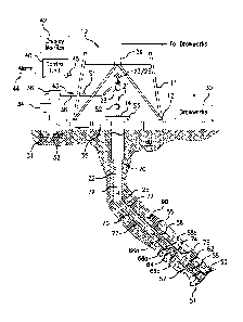
[0027] Turning now to FIG. 2, a schematic line diagram of an example system
200
that includes a first structure disposed along a second structure. At least a
part of the first or
second structure is disposed below the earth's surface. The first or second
structure may be
7
Date Recue/Date Received 2021-10-01
CA 03082143 2020-05-07
WO 2019/094730 PCT/US2018/060045
operatively connected to the equipment above the earth's surface. In the
embodiment of FIG.
2, the first structure is an inner structure 210 disposed at least partially
in an outer structure
250, as shown. However, disposing the inner structure 210 at least partially
in the outer
structure 250 is not to be understood as a limitation. The disclosed
apparatus, systems, and
methods are the same if applied to a system where a first and second structure
are disposed in
parallel and not within each other. In the embodiment of FIG. 2, the inner
structure 210 is an
inner string, including a drilling assembly 220, also known as bottom hole
assembly (BHA),
as described below. Further, as illustrated, the outer structure 250 is a
casing, a liner, or an
outer string. In another embodiment, the outer structure may be the formation
(e.g., formation
60 shown in FIG. 1). The inner structure 210 includes various tools that are
moveable within
and relative to the outer structure 250. As described herein, various of the
tools of the inner
structure 210 can act upon and/or with portions of the outer structure 250 to
perform certain
downhole operations. Further, various of the tools of the inner structure 210
can extend
axially beyond the outer structure 250 to perform other downhole operations,
such as drilling.
[0028] In the embodiment of FIG. 2, the inner structure 210 is adapted to pass
through the outer structure 250 and connect to the inside 250a of the outer
structure 250 at a
number of spaced apart locations (also referred to herein as the "landings" or
"landing
locations"). The shown embodiment of the outer structure 250 includes three
landings,
namely a lower landing 252, a middle landing 254 and an upper landing 256. The
inner
structure 210 includes a drilling assembly 220 connected to a bottom end of a
tubular
member 201, such as a string of jointed pipes or a coiled tubing. The drilling
assembly 220
includes a first disintegrating device 202 (also referred to herein as a
"pilot bit") at its bottom
end for drilling a borehole of a first size 292a (also referred to herein as a
"pilot hole"). The
drilling assembly 220 further includes a steering device 204 that in some
embodiments may
include a number of force application members 205 configured to extend from
the steering
device 204 to apply force on a wall 292a' of the pilot hole 292a drilled by
the pilot bit 202 to
steer the pilot bit 202 along a selected direction, such as to drill a
deviated pilot hole. The
drilling assembly 220 may also include a drilling motor 208 (also referred to
as a "mud
motor") configured to rotate the pilot bit 202 when a fluid 207 under pressure
is supplied to
the inner structure 210.
[0029] In the configuration of FIG. 2, the drilling assembly 220 is also shown
to
include an under reamer 212 that can be extended from and retracted toward a
body of the
drilling assembly 220, as desired, to enlarge the pilot hole 292a to form a
wellbore 292b, to at
least the size of the outer string. In various embodiments, for example as
shown, the drilling
8
CA 03082143 2020-05-07
WO 2019/094730 PCT/US2018/060045
assembly 220 includes a number of sensors (collectively designated by numeral
209) for
providing signals relating to a number of downhole parameters, including, but
not limited to,
various properties or characteristics of a formation 295, the fluid 207, and
parameters relating
to the operation of the system 200. The drilling assembly 220 also includes a
control circuit
(also referred to as a "controller") 224 that may include circuits 225 to
condition the signals
from the various sensors 209, a processor 226, such as a microprocessor, a
data storage
device 227, such as a solid-state memory, and programs 228 accessible to the
processor 226
for executing instructions contained in the programs 228. The controller 224
communicates
with a surface controller (not shown) via a suitable telemetry device 229a
that provides one-
way or two-way communication between the inner structure 210 and the surface
controller.
The telemetry unit 229a may utilize any suitable data communication technique,
including,
but not limited to, mud pulse telemetry, acoustic telemetry, electromagnetic
telemetry, and
wired pipe. A power generation unit 229b in the inner structure 210 provides
electrical power
to the various components in the inner structure 210, including the sensors
209 and other
components such as valves, motors, or actuators in the drilling assembly 220.
The drilling
assembly 220 also may include a second power generation device 223 capable of
providing
electrical power independent from the presence of the power generated using
the drilling
fluid 207 (e.g., third power generation device 240b described below).
[0030] In various embodiments, such as that shown, the inner structure 210 may
further include a sealing device 230 (also referred to as a "seal sub") that
may include a
sealing element 232, such as an expandable and retractable packer, configured
to provide a
fluid seal between the inner structure 210 and the outer structure 250 when
the sealing
element 232 is activated to be in an expanded state. Additionally, the inner
structure 210 may
include a liner drive sub 236 that includes attachment elements 236a, 236b
(e.g., latching
elements) that may be removably connected to any of the landing locations in
the outer
structure 250. The inner structure 210 may further include a hanger activation
device or sub
238 having seal members 238a, 238b configured to activate a rotatable hanger
270 in the
outer structure 250. The inner structure 210 may include a third power
generation device
240b, such as a turbine-driven device, operated by the fluid 207 flowing
through the inner
structure 210 configured to generate electric power, and a second one-way or
two-way
telemetry device 240a utilizing any suitable communication technique,
including, but not
limited to, mud pulse, acoustic, electromagnetic and wired pipe telemetry. The
inner structure
210 may further include a fourth power generation device 241, independent from
the
9
CA 03082143 2020-05-07
WO 2019/094730 PCT/US2018/060045
presence of a power generation source using drilling fluid 207, such as
batteries. The inner
structure 210 may further include pup joints 244, jars (not shown), and a
burst sub 246.
[0031] Still referring to FIG. 2, the outer structure 250 includes a liner 280
that may
house or contain a second disintegrating device 251 (e.g., also referred to
herein as a reamer
bit) at its lower end thereof. A downhole operation where a liner is involved
is generally
called a liner operation. The reamer bit 251 is configured to enlarge a
leftover portion of hole
292a made by the pilot bit 202. In aspects, attaching the inner string at the
lower landing 252
enables the inner structure 210 to drill the pilot hole 292a and the under
reamer 212 to
enlarge it to the borehole of size 292 that is at least as large as the outer
structure 250.
Attaching the inner structure 210 at the middle landing 254 enables the reamer
bit 251 to
enlarge the section of the hole 292a not enlarged by the under reamer 212
(also referred to
herein as the "leftover hole" or the "remaining pilot hole"). Attaching the
inner structure 210
at the upper landing 256, enables cementing an annulus 287 between the liner
280 and the
formation 295 without pulling the inner structure 210 to the surface, i.e., in
a single trip of the
system 200 downhole. The lower landing 252 may include a female spline 252a
and a collet
grove 252b for attaching to the attachment elements 236a and 236b of the liner
drive sub 236.
Similarly, the middle landing 254 includes a female spline 254a and a collet
groove 254b and
the upper landing 256 includes a female spline 256a and a collet groove 256b.
Any other
suitable attaching and/or latching mechanisms for connecting the inner
structure 210 to the
outer structure 250 may be utilized for the purpose of this disclosure.
[0032] The outer structure 250 may further include a flow control device 262,
such as
a backflow prevention assembly or device, placed on the inside 250a of the
outer structure
250 proximate to its lower end 253. In FIG. 2, the flow control device 262 is
in a deactivated
or open position. In such a position, the flow control device 262 allows fluid
communication
of the region between the formation 295 and the outer structure 250 and the
region within the
inside 250a of the outer structure 250. In some embodiments, the flow control
device 262 can
be activated (i.e., closed) when the pilot bit 202 is retrieved inside the
outer structure 250 to
prevent fluid communication from the wellbore 292 to the inside 250a of the
outer structure
250. The flow control device 262 is deactivated (i.e., opened) when the pilot
bit 202 is
extended outside the outer structure 250. In one aspect, the force application
members 205 or
another suitable device may be configured to activate the flow control device
262.
[0033] A reverse flow control device 266, such as a reverse flapper or other
backflow
prevention structure, also may be provided to prevent fluid communication from
the inside of
the outer structure 250 at locations above the reverse flow control device 266
to locations
CA 03082143 2020-05-07
WO 2019/094730 PCT/US2018/060045
below the reverse flow control device 266. The outer structure 250 also
includes a hanger 270
that may be activated by the hanger activation sub 238 to anchor the outer
structure 250 to the
host casing 290. The host casing 290 is deployed in the wellbore 292 prior to
further drilling
out the wellbore 292 with the system 200. In one aspect, the outer structure
250 includes a
sealing device 285 to provide a seal between the outer structure 250 and the
host casing 290.
The outer structure 250 further includes a receptacle 284 at its upper end
that may include a
protection sleeve 281 having a female spline 282a and a collet groove 282b. A
debris barrier
283 may also be provided to prevent cuttings made by the pilot bit 202, the
under reamer 212,
and/or the reamer bit 251 from entering the space or annulus between the inner
structure 210
and the outer structure 250.
[0034] To drill the wellbore 292, the inner structure 210 is placed inside the
outer
structure 250 and attached to the outer structure 250 at the lower landing 252
by activating
the attachment elements 236a, 236b of the liner drive sub 236 as shown. This
liner drive sub
236, when activated, connects the attachment element 236a to the female
splines 252a and the
attachment element 236b to the collet groove 252b in the lower landing 252. In
this
configuration, the pilot bit 202 and the under reamer 212 extend past the
reamer bit 251. In
operation, the drilling fluid 207 powers the drilling motor 208 that rotates
the pilot bit 202 to
cause it to drill the pilot hole 292a while the under reamer 212 enlarges the
pilot hole 292a to
the diameter of the wellbore 292b at at least the size of the outer string.
The pilot bit 202 and
the under reamer 212 may also be rotated by rotating the drill system 200, in
addition to
rotating one or both of them by the drilling motor 208.
[0035] In general, there are three different configurations and/or operations
that are
carried out with the system 200: drilling, reaming and cementing. In drilling
a position the
drilling assembly 220 at least partially sticks out of the outer structure 250
for enabling the
measuring and steering capability (e.g., as shown in FIG. 2). In a reaming
position, a reduced
portion of the inner structure 210, e.g., only the first disintegrating device
202 (e.g., pilot bit)
is outside the outer structure 250 to reduce the risk of stuck pipe or drill
string in case of well
collapse and the remainder of the drilling assembly 220 is housed within the
outer structure
250. In a cementing position the drilling assembly 220 is located inside the
outer structure
250 a certain distance from the second disintegrating device (e.g., reamer bit
251) to ensure a
proper shoe track.
[0036] When performing downhole operations, using systems such as that shown
and
described above in FIGS. 1-2, it is advantageous to monitor what is occurring
downhole.
Some such solutions include wired pipe (WP) where monitoring is performed
using one or
11
CA 03082143 2020-05-07
WO 2019/094730 PCT/US2018/060045
more sensors and/or devices and collected data is transmitted via special
drill pipes like a
"long cable." Another solution employs communication via mud pulse telemetry,
where the
bore fluid is used as a communication channel. In such embodiments, pressure
pulses are
generated down hole (encoded), and a pressure transducer converts the pressure
pulses into
electrical signals (encoded). Mud pulse telemetry (MPT) is in comparison with
wired pipe
very slow (e.g., by several orders of magnitude, such as a factor of one
thousand). One
specific piece of information is location. This is particularly true when a
downhole operation
is desired to be performed at a very specific point along a wellbore, such as,
but not limited
to, packer deployment, reaming, underreaming, and/or extending stablizers,
reamer blades,
latching elements, anchors, hangers, etc.
[0037] For liner drilling services, when using a system such as that shown and
described with respect to FIG. 2, it may be needed to detect or find different
positions at
locations up to 6,000 meters or greater away from the surface. Further, it may
be desirable to
know if the liner has been moving after a setting operation and to correct for
inaccuracies in
the tally sheet. In accordance with embodiments of the present disclosure,
markers are
positioned at one or more locations along an outer structure (such as a liner,
outer string,
casing, etc.) or an inner structure and a sensor is carried on an inner
structure (e.g., a drilling
assembly, an inner string, a wireline tool, etc.) or an outer structure,
respectively, which can
detect the position of the marker(s). If mud pulse telemetry communication is
employed, a
transmission time of 25 seconds or greater can occur (e.g., time from marker
detection until
the information is displayed at the surface). To account for the delay, a
large detection area
and/or a slow tripping speed may be employed. The large detection area and/or
slow tripping
speed can result in a margin of error of between 50 cm ¨100 cm. It may be
advantageous to
improve the accuracy of position detection downhole.
[0038] In accordance with embodiments of the present disclosure, optimization
of
position detection is achieved, especially via mud pulse telemetry. Further,
embodiments of
the present disclosure can eliminate slow tripping speeds to compensate low
data rate
communication(s) for position detection, which can make position detection
difficult and
expensive. In accordance with some embodiments of the present disclosure a
relatively small
detection region (i.e., for detecting a marker) is sufficient (e.g., less than
10 cm, such as 2 cm)
and can detect the exact position of the marker (e.g., with a margin of error
of about 10 cm or
less). Accordingly, a display at the surface can show the exact position of
various downhole
components based on the known position of a sensor along an inner structure.
12
CA 03082143 2020-05-07
WO 2019/094730 PCT/US2018/060045
[0039] Further, in accordance with one embodiment of the present disclosure,
it is
possible to have an inner or outer structure (with a sensor) pass an outer or
inner structure
(with a marker), respectively, without flow and thus no mud pulse telemetry
communication.
However, the system can detect the presence of the marker and thus retain
information
regarding time of interaction. Then, once circulation begins again, this time
information can
be used to determine relative positions very precisely. In such an embodiment,
in the absence
of flow, the system to detect the presence of the marker may use power
provided by an
energy storage device, such as a battery. As such, tripping or drilling speeds
during marker
finding procedures are not critical. Accordingly, no additional expensive
electrical parts are
needed to enable precise position detection, such as high precision clocks
(e.g., atomic
clocks). Furthermore, in accordance with one embodiment of the present
disclosure, it is
possible to detect multiple markers during a tripping or drilling operation.
Such multiple-
detection can enable optimization of any adjustment procedures.
[0040] Turning now to FIG 3, a schematic illustration of a system 300 in
accordance
with an embodiment of the present disclosure is shown. In this embodiment,
similar to that
described above, an inner structure 310 is adapted to pass through an outer
structure 350 and
connect to the inside 350a of the outer structure 350 at a number of spaced
apart locations
(also referred to herein as the "landings" or "landing locations"). The shown
embodiment of
the outer structure 350 includes three landings, namely a lower landing 352, a
middle landing
354 and an upper landing 356. The inner structure 310 includes a drilling
assembly 320
located on a lower end thereof, similar to that shown and described above.
[0041] As noted above, the inner structure 310 can interact with the outer
structure
350, such as through engagement between an inner downhole tool 358 that is
part of the inner
structure 310 and the landings 352, 354, 356 of the outer structure 350. In
some
embodiments, the inner downhole tool 358 is a downlinkable running tool that
can extend
one or more elements to engage with the landings 352, 354, 356, as will be
appreciated by
those of skill in the art. Although shown and described herein with respect to
an engagement
between a running tool included in an inner structure and a landing in an
outer structure,
those of skill in the art will appreciate that any type of downhole operation
that is based on
position can be carried out and employ embodiments of the present disclosure.
For example,
the running tool and the landing may be part of the outer and inner structure,
respectively.
Further, the disclosed apparatus, systems, and methods are the same if applied
to a system
where a first and second structure are disposed in parallel and not within
each other and at
13
CA 03082143 2020-05-07
WO 2019/094730 PCT/US2018/060045
least one marker and at least one sensor as well as a landing and a running
tool is located in
either one of the first and second structure.
[0042] As discussed above, knowledge regarding the relative positioning of an
inner
structure relative to an outer structure is important to be able to carry out
certain downhole
operations. For example, with reference to FIG. 3, to achieve appropriate
engagement
between the inner downhole tool 358 and the landings 352, 354, 356 of the
outer structure
350, it is important to know the relative positions between the inner
structure 310 and the
outer structure 350 with high accuracy.
[0043] To achieve accurate relative position measurement, one of the inner
structure
310 or the outer structure 350 can be configured with one or more markers and
the respective
outer structure 350 or inner structure 310 can include one or more sensors
that are selected to
detect the proximity of the markers For example, the landings 352, 354, 356
can each
include one or more markers positioned around or at a known distance to the
respective
landing 352, 354, 356. The inner structure 310 can include one or more sensors
that are
located at a known distance to the inner downhole tool 358 of the inner
structure 310. For
instance, the one or more sensors may be located on and/or proximate to the
inner downhole
tool 358 of the inner structure 310. The sensors on the inner structure 310
can monitor a
signal that is generated by or generated through interaction with the marker
of the outer
structure 350. The signal can be dependent upon distance between the sensor
and the marker.
[0044] Turning now to FIGS. 4A-4B, schematic illustrations of a system 400
having
an outer structure 450 with a position marker 402 that is part of a position
detection system
404 in accordance with an embodiment of the present disclosure are shown.
Further, the
system 400 includes an inner structure 410 that can be run within and relative
to the outer
structure 450.
[0045] Although shown and described in FIGS. 4A-4B with various specific
components configured in and on the inner structure 410 and the outer
structure 450, those of
skill in the art will appreciate that alternative configurations with the
presently described
components located within an outer structure (e.g., a liner) are possible
without departing
from the scope of the present disclosure. For example, the marker may be
located on the inner
structure 410 and detected by a sensor in the outer structure 450. The inner
structure 410
and/or the outer structure 450 may include one or more components, including,
but not
limited to, packers, reamers, underreamers, extendable stabilizers, anchors,
latching elements,
hanger activation tools, liner drive subs, workover tools, milling tools,
cutting tools, and/or
communication devices, such as couplers, e.g., inductive couplers, capacitive
couplers,
14
CA 03082143 2020-05-07
WO 2019/094730 PCT/US2018/060045
electromagnetic resonant couplers, or acoustic couplers. In the non-limiting
example, such as
that shown in FIGS. 4A-4B, the outer structure 450 may include a part of the
position
detection system 404 (e.g., a marker). The marker may comprise magnetic,
optical, acoustic,
electromagnetic, mechanical, electromechanical, electric, radio frequency
identification (also
known as RFID), radioactive, and/or radiation markers. For example, markers of
various
embodiments of the present disclosure can include a magnet, a radioactive
source, an
electromagnetic transmitter, an electromagnetic transceiver, a radio-frequency
identifier
(RFID), a region of high or low conductivity, permittivity, susceptibility, or
density, a recess
formed in the inner or outer structure (i.e., mechanical features), an optical
source, a coil,
and/or stator windings. Radio-frequency identifiers, in particular, may
comprise a transmitter
and/or receiver, an energy store, and electronic device and may be used to
read identification
of the RFID markers when detecting them or may be arranged to modify a state
of the RFID
marker (e.g., increase the status of a counter). Markers may comprise a group
of individual
markers, wherein the group of individual markers may comprise the same kinds
of markers or
different kinds of markers.
[0046] In one non-limiting embodiment, the position marker 402 is a magnetic
ring
configuration that is installed within a section of the outer structure 450
(shown having
various components to house the position marker 402). However, as noted, those
of skill in
the art will appreciate that the position marker 402 can take any number of
configurations
without departing from the scope of the present disclosure. For example,
magnetic markers,
radioactive markers such as gamma markers, capacitive markers, conductive
markers,
tactile/mechanical components, temperature or heat markers, optical markers,
etc. can be
used to determine a relative position between the outer structure 450 and the
inner structure
410 (e.g., in an axial and/or rotational manner to each other) and thus
comprise one or more
features of a position marker in accordance with the present disclosure.
[0047] Detection of the position marker 402 can be made by a sensor 406 of the
position detection system 404 that is part of and/or mounted to the inner
structure 410. The
sensor 406 is coupled to downhole electronics 408 that are also part of the
inner structure 410
(e.g., part of an electronics module on or within the inner structure 410).
For example, the
sensor 406 can be a magnetic field sensor such as a magnetometer (e.g., a Hall
sensor,
magnetoresistive sensor, or a fluxgate sensor) that detects the appearance
and/or strength of a
magnetic field that is generated by the position marker 402. Other sensors
that may be
employed include, but are not limited to, a sensor for radioactive radiation
(e.g., gamma
radiation) such as a scintillation crystal (e.g., a NaI scintillation crystal
or a counter tube) that
CA 03082143 2020-05-07
WO 2019/094730 PCT/US2018/060045
detects the appearance and/or strength of radioactive radiation, a sensor for
capacity or
permittivity that detects the appearance and/or strength of capacity or
permittivity, a sensor
for resistivity, conductivity, resistance, or conductance such as an electrode
(e.g., an electrode
arrangement) or a coil (e.g., a coil arrangement) that detects the appearance
and/or strength of
resistivity, conductivity, resistance, or conductance, a light sensor that
detects the appearance
and/or strength of light, a tactile or standoff sensor such as a mechanical or
acoustic standoff
sensor that detects the appearance and/or amount of standoff or distance
variations, and a heat
or temperature sensor that detects the appearance of heat and/or temperature
variations. The
downhole electronics 408 can be one or more electronic components that are
configured in or
on the inner structure 410 and/or a downhole tool of the inner structure 410,
and can be part
of an electronics module, as will be appreciated by those of skill in the art.
In other
embodiments, an electronics device (e.g., an electrical wire) can be used
instead of the
downhole electronics 408.
[0048] FIG. 4A is a cross-sectional illustration of a portion of the system
400
including the position marker 402 in the outer structure 450 and the sensor
406 of the inner
structure 410 configured to move relative to the position marker 402. FIG. 4B
is an enlarged
illustration of the position marker 402 as indicated by the dashed circle in
FIG. 4A.
[0049] In some embodiments, the position detection system 404 can be operably
connected to or otherwise in communication with downhole electronics 408 of
the inner
structure 410 and/or in communication to the surface. Communication from the
position
detection system 404 can include position information and/or information from
which
information related to a position can be extracted. For example, a signal
strength can be used
to determine relative positions of the sensor 406 and the position marker 402
if the signal
strength is dependent upon a distance between the sensor 406 and the position
marker 402.
[0050] Specific downhole operations can be contingent on the specific relative
positions of the inner structure 410 relative to the outer structure 450. For
example, properly
engaging, disengaging, and moving at least parts of the inner structure 410
relative to the
outer structure 450 can be achieved by using knowledge of the relative
positions of the two
parts of the system 400. By knowing the relative position of the inner
structure 410 to the
outer structure 450, anchor modules, latching elements, packers, measurement
tools, testing
tools, reamers, such as underreamers, extendable stabilizers, anchors, hanger
activation tools,
liner drive subs, workover tools, milling tools, cutting tools and/or
communication devices,
such as couplers, e.g., inductive couplers, capacitive couplers,
electromagnetic resonant
couplers, or acoustic couplers, etc., can be appropriately engaged and/or
operated at desired
16
CA 03082143 2020-05-07
WO 2019/094730 PCT/US2018/060045
locations downhole. For example, the position detected by the position
detection system 404
can be communicated to the surface to inform about the location of the inner
structure 410
relative to an exact position of the position marker 402.
[0051] In the non-limiting embodiment shown in FIGS. 4A-4B, the position
marker
402 includes a magnetic ring 412 that has opposed north and south poles 414,
416 as shown.
In other embodiments, the opposite or differing pole orientation than that
shown can be used.
Further, in still other alternative embodiments, the position marker 402 can
be formed of a
different detectable material and/or structure, as noted above. In this
embodiment, the
magnetic ring 412 is a full 360 degree ring (e.g., wrapped around and in the
outer structure
450). In other embodiments, a magnetic ring can be split such that less than
360 degrees is
covered by the magnetic ring. Further, in other embodiments, the magnetic ring
can have
overlapping ends such that the magnetic ring wraps around more than 360
degrees of the
outer structure 450. Further still, other configurations can employ spaced
magnetic elements,
such as buttons, that form the position marker 402.
[0052] The magnetic ring 412 of the position marker 402 creates a magnetic
field that
can be detected by and/or interact with components or features of the inner
structure 410 such
as the sensor 406. Further, advantageously, ring-shaped position marker 402 as
shown in
FIGS. 4A-4B (e.g., magnetic ring 412) can be utilized independent of the
orientation of the
inner structure 410 because, for a ring-shaped marker, the orientation in and
relative to the
outer structure 450 is irrelevant in detection of a signal. Accordingly,
detection of the location
of inner structure 410 relative to the outer structure 450 can be easily
achieved. Detection can
be achieved, in part, by processing the sensor signal, the processing carried
out by the
downhole electronics 408, and such processing and/or data can be communicated
to the
surface. Once the detection is communicated to the surface that the position
marker 402 is
detected, it may be desirable to position the inner structure 410 with
precision so that a
desired downhole operation can be performed at a precise location.
[0053] Turning now to FIG. 5, a flow process 500 for detecting a position of
an inner
structure relative to an outer structure in accordance with the present
disclosure is shown. The
flow process 500 can be performed by downhole systems as shown and described
herein.
Particularly, the flow process 500 is performed at least partially downhole
with a first
structure having at least one position marker and a second structure that is
moveable along
and relative to the first structure or vice versa. For example, the flow
process 500 may be
performed downhole with an outer structure having at least one position marker
and an inner
structure that is moveable within and relative to the outer structure or vice
versa. For
17
CA 03082143 2020-05-07
WO 2019/094730 PCT/US2018/060045
example, in some embodiments, the outer structure can be a liner or outer
string and the inner
structure can be an inner string. Further, in other embodiments, the inner
structure can be a
wireline tool that is conveyed within an outer structure such as a liner or
casing. Various
other configurations are possible without departing from the scope of the
present disclosure.
[0054] At block 502, the inner structure is moved downhole relative to an
outer
structure. The inner structure includes at least a sensor and the outer
structure includes the
position marker that is detectable by the sensor of the inner structure. The
position marker is
located along the outer structure to enable knowledge of when the inner
structure is near
and/or passes the position marker during relative movement of the inner
structure and the
outer structure. In an alternative embodiment, the inner structure includes a
marker and the
outer structure includes the sensor. In one embodiment, e.g., when the inner
structure
includes the marker and the outer structure includes the sensor, the
communication path to
the surface may include at least a part that utilizes wireless communication.
[0055] At block 504, the sensor detects the position marker. The detection can
be a
strength of a detected signal, property, characteristic, etc., that is based
on the sensor-position
marker configurations. For example, when using a magnetic sensor/marker
configuration,
magnetic field strength or magnetic flux density can be the detected property.
When using a
radiation based sensor/marker, the detected property can be a count or count-
per-second (i.e.,
activity). Various other detected properties can be employed based on the
specific
sensor/marker configuration, including, but not limited to, induced currents,
voltages, optical
patterns, optical strength, acoustic signals, electromagnetic signals,
geometric features, and/or
radiation. etc.
[0056] The sensor is connected to electronics that can record the detected
property of
the marker, and thus a detection-versus-time can be achieved. The combination
of the sensor
and electronics (whether separate or integral with the sensor) can be
configured to monitor
for a critical event such as a critical value of the detected property.
Processing may be
involved, such as the application of calibrations, corrections, calculation of
averages,
standard deviations, or other statistical functions. In various configurations
the critical event
can be a peak value or peak strength of the detected property (e.g., strongest
magnetic field,
highest count-per-second, etc.). However, in other configurations, the
detected critical event
can be a change in polarity (such as a magnetic z-field sensor would sense
when passing one
or more magnets, such as dipole magnets, with the dipole axis pointing
perpendicular to the
trajectory of the passing magnetic z-field sensor), a crossing of a positive
to a negative value
(e.g., change in voltage sign). Further, in some embodiments the critical
event can be a
18
CA 03082143 2020-05-07
WO 2019/094730 PCT/US2018/060045
feature of a detected curve, e.g., characterized by a specific value the
first, second, etc.
derivative of the detected curve or alignment of one or more curves generated
by interaction
of the sensor with the marker. Still further, a critical event can be defined
a predetermined
time after one or more features that may be understood as critical events as
discussed above.
[0057] At block 506, the sensor/electronics determine that the critical event
has been
detected. If the critical event is a peak in the sensor response, detecting of
the critical event
can be based on an increasing signal strength and then a decreasing signal
strength, and the
system determines that the critical event occurred at a time just before the
signal strength
decreased. In some embodiments, the critical event can be a known event (e.g.,
a change in
polarity or voltage) and/or a specific known or predetermined value, and thus
the critical
event can be detected. In some embodiments, the time of the critical event can
be calculated
based on the time of detection or other times that are related to the detected
signal. For
instance, the time of the critical event could be the average of the time when
the signal was
first detected and the time when the signal level falls below noise level(s).
Further, in some
embodiment, the critical event can be an expected value or range of values
that is based on
testing and accounting for real-world variability and/or error. Thus, the
critical event is not
limited to a single test and/or detection process or algorithm.
[0058] At block 508, with the critical event detected, the system will count
or
determine or monitor a time-since-critical event which is the time since the
critical event
occurred or since the critical event was detected. The counting can be based
on a timestamp
of the detection or occurrence of the critical event or a timestamp that is
related to the
detection or occurrence of the critical event, e.g., a predetermined time
period before or after
the critical event was detected. In some embodiments, a clock or timer can
start once the
critical event had occurred or is detected or start a known time period after
the critical event
has occurred or was detected. In either event, a time since the critical event
is detected or has
occurred can be obtained.
[0059] At block 510, a signal is transmitted to the surface from the inner
structure
regarding position, e.g., regarding position of the inner structure relative
to the outer
structure. The signal includes the time-since-critical event. The end of the
time period of the
time-since-critical event may be the event of transmission of the signal or a
time that is
related to the event of transmission of the signal, e.g., a time that includes
additional time
periods such as processing times, transmission times, or a predefined time
interval before or
after the transmission of the signal occurs. Accordingly, the time-since-
critical event
represents a time period which is related to the time when the marker is
passed by the sensor
19
CA 03082143 2020-05-07
WO 2019/094730 PCT/US2018/060045
or vice versa. Accordingly, any subsequent travel of the inner structure
relative to the outer
structure can be determined.
[0060] At block 512, the transmitted signal is received at the surface and
processed to
determine a position of the inner structure. Specifically, the processing
includes a summation
of the time-since-critical event and a processing time, which may be a known
time or a
calculated time and may be part of the system as a whole. The processing time
may include
the transmission time, i.e., the time from transmitting from the inner
structure until the signal
reaches a receiver at the surface. The transmission time often depends on
operational
parameters, such as depth and/or type of fluid, and may be determined by
taking the
operational parameters into account. For example, the transmission time
typically increases
with increasing depth of the borehole and is usually higher for water-based
mud than for oil-
based mud. The transmission time may be calculated based on operation
parameters or may
be taken from a look-up table. The look-up table may be a conventional look-up
table,
typically printed on paper, or a look-up table that is electronically
accessible, such as by a
processing system executing software instructions to determine the
transmission time. The
determination of the transmission time may be based on lab measurements and/or
theoretical
considerations. The transmission time may also be measured exemplarily for a
drilling run or
for each transmission, individually.
[0061] Further, the processing time may include any processing time that
occurs on
surface or downhole, such as processing in the electronics for preparing the
transmitted signal
(e.g., applying compensation, correction, or calibration algorithms to
measurements,
encoding or decoding information, repeating or amplifying signals, applying
data
compression schemes and/or telemetry correction techniques known in the art,
converting
analog signals to digital signals or vice versa, such as converting electronic
analog signals to
digital electronic signals or vice versa or converting electronics digital
information into a
mud pulse or vice versa for mud pulse telemetry). The processing performed at
block 512 can
include determination of a total time delay that includes both the time-since-
critical event and
any known system time delay including, but not limited to, the processing time
that may
include transmission time and other calculated, predetermined, or otherwise
known time
intervals.
[0062] At block 514, the processed signal allows for a correlation of relative
position
between the inner structure and the outer structure, which accounts for any
relative movement
since the time of the critical event. By determining the depth-related data,
such as the block
height or the depth that was acquired by the surface depth tracking system at
the time of the
CA 03082143 2020-05-07
WO 2019/094730 PCT/US2018/060045
critical event, the relative position of the outer and inner structure may be
identified at any
later time, such as the time of the critical event plus the total time delay.
As such, the precise
position of the inner structure relative to the outer structure can be known.
[0063] Alternatively, instead of transmitting the time-since-critical event,
the
measured time of the critical event can be transmitted to the surface, e.g.,
as a time stamp.
However, transmitting a time stamp typically may require more data bits as
compared to
transmitting a time-since-critical event, because the expected value range for
a time stamp
divided by the required numeric resolution is much higher for the time stamp
than that for the
time-since-critical event. For instance, if the expected value range for the
time stamp is two
weeks and the required numeric resolution is one minute, the time stamp would
be digitized
in at least two weeks / one minute, which equals 20,160 levels which would
require 15 bits.
In contrast, if the expected value range for the time-since-critical event is
ten minutes and the
required numeric resolution is one minute, the time-since-critical event can
be digitized in no
more than ten levels corresponding to four bits. In addition, transmitting the
time stamp
would rely upon the accuracy of the downhole clock being comparable with the
accuracy of
the surface clock. Downhole clocks, however, are subject to harsh environments
in which
they are used, including enhanced temperatures and high temperature
variations, and may be
subject to inaccuracies such as drifts, etc. The amount of such inaccuracies
typically increases
with time, and thus it is beneficial to transmit only the relatively short
time-since-critical
event instead of the time stamp. The problem of drifting downhole clocks,
however, can be
mitigated by repeated synchronization with a more accurate clock on surface or
downhole.
[0064] At block 516, a downhole operation is performed based on the correlated
position. Such downhole operation can include adjusting the physical position
of the inner
structure relative to the outer structure. For example, the time-since-
critical event, the
processing time, and/or the total time delay can be indicative of an
"overshoot" or additional
relative travel between the inner and outer structures. By determining the
depth-related data,
such as the block height or the depth that was acquired by a surface depth
tracking system at
the time when the critical event has occurred or was detected by the downhole
sensor, a
reverse operation can be used to move the inner structure to a specific
location where the
critical event has occurred or was detected. Alternatively, the inner
structure may be moved
to a specific location at a distance, e.g., a predefined distance, from the
location where the
critical event has occurred or was detected.
[0065] At the specific location, a downhole operation may be performed which
can
be, in combination or alternatively, an actuation or action. Such actuation or
action can
21
CA 03082143 2020-05-07
WO 2019/094730 PCT/US2018/060045
include extension of anchors, latching elements, stabilizers, or blades such
as reamer or
underreamer blades, activation of packers, hanger activation tools, liner
drive subs, workover
tools, milling tools, cutting tools and/or communication devices, such as
couplers, e.g.,
inductive couplers, capacitive couplers, electromagnetic resonant couplers, or
acoustic
couplers, testing or sampling (e.g., fluid testing or coring) a formation,
retraction of blades,
such as reamer or underreamer blades, and/or other actions where it may be
advantageous to
be performed at a very specific location. For example, positioning the inner
structure relative
to the outer structure such that engagement with a landing of the outer
structure can be
achieved (e.g., as shown and described with respect to FIGS. 2-3).
[0066] In some configurations, the time of the critical event can be stored in
memory
until it can be sent to the surface. In this case, the transmission time can
be determined with
high accuracy, which leads to an overall improvement of the total time delay
determination.
For example, in some embodiments, loss of mud-flow can result in a loss of
power and/or a
time delay in transmission. Further, in some embodiments, the transmission
media itself may
not be present, such as a lack of mud that is capable of mud pulse telemetry
during a tripping
event. Then, when the signal is finally sent to the surface, one or more
critical events can be
allocated in time, corresponding locations can be determined and appropriate
action can be
taken. The information, once at the surface, can be visualized based on user
needs.
[0067] Thus, in accordance with embodiments of the present disclosure, time-
since-
critical event measurement can be used to accurately determine a delay from an
event and
thus a precise absolute and/or relative position of downhole elements can be
obtained.
Advantageously, the transmission is merely a time delay, and thus with
recording and
transmitting the time delay instead of an absolute time stamp of the peak
detection, no clock
synchronization is required. This is particularly advantageous because a
downhole time can
differs from uphole time, e.g., due to temperature differences between the two
locations, with
time difference typically increasing over time.
[0068] Although shown and described above with respect to a single sensor on
the
inner structure, those of skill in the art will appreciate that the present
disclosure is not so
limited. For example, multiple sensors (on the inner or outer structure)
and/or markers (on the
outer or inner structure, respectively) can be used for downhole operations.
For example,
multiple markers could follow a particular, predetermined pattern at a "marker
position," e.g.,
two markers in close proximity at a first marker position and three markers in
close proximity
at a second marker position. Such marker positions, with multiple markers, can
enable marker
22
CA 03082143 2020-05-07
WO 2019/094730 PCT/US2018/060045
coding. In this fashion, different positions along the length of the outer
structure can be
identified.
[0069] As noted above, embodiments of the present disclosure can be included
in
steerable drilling liners (e.g., as shown in FIGS. 2-3) with an inner string
and an outer string.
Alternative configurations can be employed for monitoring, adjusting and/or
aligning a
position of tools comprising anchors, latching elements, stabilizers, or
blades such as reamer
or underreamer blades, such as, but not limited to, packers, hanger activation
tools, liner drive
subs, workover tools, milling tools, cutting tools, wireline tools, and/or
communication
devices, such as couplers, e.g., inductive couplers, capacitive couplers,
electromagnetic
resonant couplers, or acoustic couplers, testing or sampling (e.g., fluid
testing or coring)
tools, retraction of blades, such as reamer or underreamer blades, or other
tools or devices
that are disposed within or along a casing or liner or any other type of
tubular equipment that
has markers or marker sensing sensors disposed along such tubular and/or other
actions
where it may be advantageous to be performed at a very specific location.
[0070] Advantageously, the total time delay (including the time-since-critical
event
and the processing time) can be used to accurately adjust a position of
various downhole
components to be used for specific downhole operations at specific locations.
As such, very
accurate placement of downhole tools (e.g., parts of the inner structure) can
be achieved.
[0071] In some embodiments, several markers can be detected by a single
sensing
element before the time-since-critical event data is transmitted to surface.
That is, the time-
since-critical event data can include multiple time-since-critical event
calculations. This may
happen if no telemetry is available, such as during tripping events. The
sensor of the inner
structure would detect the different markers of the outer structure when
passing the markers
and will record the time since the condition of the sensor signal was met for
at least one of
the different markers. Once telemetry is available again, the different time
delays (e.g.,
different time-since-critical events) or time stamps belonging to the
detection of the different
markers are transmitted uphole to the surface.
[0072] Advantageously, embodiments provided herein provide methods and systems
to determine a precise position of downhole elements relative to each other.
Further, methods
and systems for initiating downhole operations in a borehole are provided. In
accordance with
embodiment of the present disclosure, a first structure, such as an inner
structure (e.g., an
inner tool, inner string, wireline tool, etc.) is disposed along (e.g.,
within) a second structure,
such as an outer structure (e.g., borehole, casing, outer string, liner,
etc.). The first structure is
equipped with one or more sensors and the second structure is equipped with
one or more
23
CA 03082143 2020-05-07
WO 2019/094730 PCT/US2018/060045
markers or vice versa. The locations of the sensors and/or the markers can be
predetermined
and set to signify specific locations of one or both of the first and second
structures.
[0073] A sensor system is used to monitor for a signal that is generated by
the marker
and/or interaction with the marker (depending on the sensor/marker
configuration). The
sensor system will monitor for a critical event or event that is related to
the signal that the
sensor is detecting. The sensor system will then record a time-since-critical
event.
[0074] The sensor system or downhole electronics will transmit with a
transmitter
data from downhole to the surface indicating the time-since-critical event. A
processor (at the
surface or downhole) will determine a total time delay based on the time-since-
critical event
and any known processing times, transmission times, waiting times, and/or
other time delays.
[0075] Once the total time delay is obtained, precise information regarding
relative
position of the first structure and the second structure can be determined.
Based on this,
instructions can be sent from the surface to initiate a downhole operation.
The downhole
operation can include adjusting the relative positions of the first and second
structures based
on the calculated relative positions and/or performing a specific operation
knowing the
precise locations of the first and second structures.
[0076] Those of skill in the art will appreciate that depth is not
specifically part of the
relative positions of the inner and outer structures. At the surface, a known
time delay is
either received, calculated, measured, or otherwise determined, or is known
(e.g., in case of a
predetermined constant time delay, e.g. with a constant logging speed) and
combined with the
processing time, transmission time, and/or the time-since-critical event. The
time delay can
be used to locate the position of the marker relative to the sensor (reverse
of the above
described operation) and a specific operation can be performed. That is, it is
not necessary to
record anywhere the depth where the marker is, but rather only the relative
positions, based
on the measured or calculated time-since-critical event is needed. However, in
an alternative
embodiment, the relative position in combination with the depth tracking may
be used to
calculate and/or display an absolute position.
[0077] In accordance with embodiments of the present disclosure, it is even
possible
to leave out any time-depth correlation and determine the location of the
marker position (or
sensor position) only via a time-reversed movement of the inner structure. In
this manner, a
wrong time-depth correlation or failure in a tally sheet could be identified
or overcome.
[0078] Advantageously, embodiments provided herein enable measuring the
position
of one structure relative to another structure, and thus a position for
downhole operations can
be precisely measured. For example, in one non-limiting example employing
embodiments
24
disclosed herein, a measurement of a position for latch-in contact can be
precisely identified
and/or measured. The latch-in can be between a running tool with extendable
elements and a
landing of an outer liner, casing, or string. Such position measurement can be
verified using
embodiments of the present disclosure (e.g., multiple sensors relative to
multiple markers at
different locations), corrections can be made for imprecise tally, pipe
stretch, and/or other
unforeseen failures and/or events (e.g., liner movement).
[0079] Further, advantageously, embodiments provided herein enable precise
relative
position measurement that is completely independent of the transmission
technology or method
of communication. Accordingly, any time an opportunity is provided to send the
time-since-
critical event information, such information can be sent, regardless of the
communication type. As such, there is no extra time needed to find a specific
position, e.g., in
the event of tripping, embodiments described herein can be employed, and so no
subsequent
position measurement is needed after tripping is complete. Further, the
information can be sent
whenever a communication channel is available.
[0080] Moreover, as noted above, marker coding is possible wherein different
positions indicated by markers can be coded such that a relative position
between an inner
structure and an outer structure can be obtained accurately. Furthermore,
multiple different
positions can be measured and/or detected independently from each other using
multiple
markers at different locations along an outer structure_
[0081] Further, advantageously, embodiment provided herein allow for
correction for
transmission time and latency. Thus, precise position measurements can be
obtained even with
very slow communication channels, such as mud pulse telemetry. Moreover, no
special
equipment is required for transmission of the obtained time-since-critical
event data. For
example, utilization of wired pipe is possible but not required, and yet very
precise position
information can be obtained.
[0082] Moreover, because the detection of the marker by the sensor is based on
a critical
event (or value), high relative speeds between the inner and outer structures
used during for
example, tripping events, do not impact the reliability of embodiments of the
present disclosure.
Further, the amount of material used to form the marker in the outer structure
can be reduced as
compared to prior position measurement techniques. That is, only a specific
critical event is
required to be detected and not the actual position of the inner structure
(which might require a
large marker).
[0083] In support of the teachings herein, various analysis components may be
used
including a digital and/or an analog system. For example, controllers,
computer processing
Date Recue/Date Received 2021-10-01
systems, and/or geo-steering systems as provided herein and/or used with
embodiments
described herein may include digital and/or analog systems. The systems may
have
components such as processors, storage media, memory, inputs, outputs,
communications
links (e.g., wired, wireless, optical, or other), user interfaces, software
programs, signal
processors (e.g., digital or analog) and other such components (e.g., such as
resistors,
capacitors, inductors, and others) to provide for operation and analyses of
the apparatus and
methods disclosed herein in any of several manners well-appreciated in the
art. It is
considered that these teachings may be, but need not be, implemented in
conjunction with a
set of computer executable instructions stored on a non-transitory computer
readable
medium, including memory (e.g., ROMs, RAMs), optical (e.g., CD-ROMs), or
magnetic
(e.g., disks, hard drives), or any other type that when executed causes a
computer to
implement the methods and/or processes described herein. These instructions
may provide for
equipment operation, control, data collection, analysis and other functions
deemed relevant
by a system designer, owner, user, or other such personnel, in addition to the
functions
described in this disclosure. Processed data, such as a result of an
implemented method, may
be transmitted as a signal via a processor output interface to a signal
receiving device. The
signal receiving device may be a display monitor or printer for presenting the
result to a user.
Alternatively or in addition, the signal receiving device may be memory or a
storage medium.
It will be appreciated that storing the result in memory or the storage medium
may transform
the memory or storage medium into a new state (i.e., containing the result)
from a prior state
(i.e., not containing the result). Further, in some embodiments, an alert
signal may be
transmitted from the processor to a user interface if the result exceeds a
threshold value.
[0084] Furthermore, various other components may be included and called upon
for
providing for aspects of the teachings herein. For example, a sensor,
transmitter, receiver,
transceiver, antenna, controller, optical unit, electrical unit, and/or
electromechanical unit
may be included in support of the various aspects discussed herein or in
support of other
functions beyond this disclosure.
[0085] The use of the terms "a" and "an" and "the" and similar referents in
the
context of describing the invention (especially in the context of the
following claims) are to
be construed to cover both the singular and the plural, unless otherwise
indicated herein or
clearly contradicted by context. Further, it should further be noted that the
terms "first,"
"second," and the like herein do not denote any order, quantity, or
importance, but rather are
used to distinguish one element from another. The modifier "about" used in
connection with
a quantity is inclusive of the stated value and has the meaning dictated by
the context (e.g., it
26
Date Recue/Date Received 2021-10-01
includes the degree of error associated with measurement of the particular
quantity).
[0086] The flow diagram(s) depicted herein is just an example. There may be
many
variations to this diagram or the steps (or operations) described therein
without departing
from the scope of the present disclosure. For instance, the steps may be
performed in a
differing order, or steps may be added, deleted or modified. All of these
variations are
considered a part of the present disclosure.
[0087] It will be recognized that the various components or technologies may
provide
certain necessary or beneficial functionality or features. Accordingly, these
functions and
features as may be needed in support of the appended claims and variations
thereof, are
recognized as being inherently included as a part of the teachings herein and
a part of the
present disclosure.
[0088] The teachings of the present disclosure may be used in a variety of
well
operations. These operations may involve using one or more treatment agents to
treat a
formation, the fluids resident in a formation, a wellbore, and / or equipment
in the wellbore,
such as production tubing. The treatment agents may be in the foim of liquids,
gases, solids,
semi-solids, and mixtures thereof Illustrative treatment agents include, but
are not limited to,
fracturing fluids, acids, steam, water, brine, anti-corrosion agents, cement,
permeability
modifiers, drilling muds, emulsifiers, demulsifiers, tracers, flow improvers
etc. Illustrative
well operations include, but are not limited to, hydraulic fracturing,
stimulation, tracer
injection, cleaning, acidizing, steam injection, water flooding, cementing,
etc.
[0089] While embodiments described herein have been described with reference
to
various embodiments, it will be understood that various changes may be made
and equivalents
may be substituted for elements thereof without departing from the scope of
the present
disclosure. In addition, many modifications will be appreciated to adapt a
particular
instrument, situation, or material to the teachings of the present disclosure
without departing from
the scope thereof. Therefore, it is intended that the disclosure not be
limited to the particular
embodiments disclosed as the best mode contemplated for carrying the described
features, but that
the present disclosure will include all embodiments falling within the scopeof
the appended
claims.
[0090] Accordingly, embodiments of the present disclosure are not to be seen
as
limited by the foregoing description, but are only limited by the scope of the
appended
claims.
27
Date Recue/Date Received 2021-10-01