Note: Descriptions are shown in the official language in which they were submitted.
CA 03082155 2020-05-07
WO 2019/091536 PCT/D1(2018/050296
1
Screw with two set of ribs in a knurled region and use thereof
The present invention relates to a screw, especially a wood-screw, with a
knurled re-
gion.
Background of the invention
For a proper and smooth driving of a screw into a material, especially a
flexible mate-
rial, such as wood, it is common practice to provide the shank with a knurled
region in
order to enlarge the hole made by the screw and minimize friction. Various
types of
knurls exist on screws, for example straight or twisted serrations, single
knurled re-
gions or multiple knurled regions, and various shaped of the serrations.
Different
types have been developed for different materials.
Examples are given in patent documents W02010/034390, US6000892, US6616391,
US9709086, US2007/237606, US2015/184685, US2014/294534, EP2458233,
EP2522864, DE102004018069, DE102005039744, DE102008057678, and
DE202004011145U1.
However, despite knurls having existed in screws for many years, there is
still an on-
going effort for optimizing screws by providing improved knurled regions.
Description of the invention
It is the objective of the invention to provide an improvement in the art. In
particular,
it is an objective to provide a screw with improved capabilities for screwing
in fibrous
material, especially wood. This objective is achieved with a screw as
explained in
greater detail in the following. In particular, the screw as described below
has an in-
creased milling efficiency in wood and other fibrous material.
The screw comprises a screw-head at a first end of the screw and a shank
extending
from the screw-head towards an opposite, second end of the screw. The screw
has a
longitudinal central axis extending between the first end and the second end.
A thread
is provided on the shank at or near the second end for screwing the screw into
a mate-
rial by a fastening-tool.
CA 03082155 2020-05-07
WO 2019/091536 PCT/D1(2018/050296
2
Between the thread and the head, a knurled region is provided. The knurled
region has
a first end and a second end that is opposite to the first end, and a middle
that is mid-
way there between. A typical length L of the knurled region relatively to the
total
length of the screw is in the range of 1-40%.
A first and second set of knurling ribs is provided between the first and the
second end
of the knurled region, wherein the first set is offset relatively to the
second set by an
azimuth angle of at least 10 . If the ribs are provided with identical angular
distance
between neighboring ribs, the offset is typically half this angular distance.
The first set extends from the first end towards the second end but not all
the way to
the second end. In other words, the ribs of the first set are ending remotely
from the
second end. For example, when measured along the central axis, the length of
the first
set of ribs is less than 90% of the length of the knurled region, optionally
less than
80% or even less than 70%. The first set and the second set of ribs are
intertwined
only in an overlap region. As the first set of ribs does not extend to the
second end of
the knurled region, the overlap region is remote from the second end.
In some embodiments, the second set of ribs extends all the way from the
second end
to the first end of the knurled region, but the first set extends from the
first end only to
a position that is remote from the second end. In this case, the overlap
region extends
from the first end and until the position where the ribs of the first set are
ending,
which is remote from the second end.
In other embodiments, the second set of ribs extends from the second end
towards the
first end but not all the way to the first end, so that the overlap region is
not only re-
mote from the second end but also remote from the first end of the knurled
region. In
this case, the two sets of ribs extends towards each other from opposite ends
of the
knurled region and are intertwined in an overlap region that is remote from
both ends.
For example, the overlap region is centered at the middle of the knurled
region. Op-
tionally, when measured along the central axis, the length of the second set
of ribs is
CA 03082155 2020-05-07
WO 2019/091536 PCT/D1(2018/050296
3
less than 90% of the length of the knurled region, optionally less than 80% or
even
less than 70%.
Optionally, the screw has one or more of the following parameters
- a length of the overlap region in the range of 3-30% of the length L of the
knurled
region;
- a number of ribs of the first set and/or the second set in the range of 3-
12;
- identical number of ribs in the first set and the second set;
- identical angular distance between the ribs in the first set and the ribs
in the second
set; optionally the offset in the azimuth angle between the first set and the
second set
is half the angular distance between the ribs;
- the ribs of both sets twisted helically around part of the shank in the
knurled region,
optionally twisted by a helix angle V1 in the range of 20-75 , optionally 30-
60 rela-
tively to the central axis;
- the knurled region is provided in immediate extension of the thread;
- the knurled region is provided at a distance Z remotely from the head,
wherein Z is
in the range of 5-90% of the length of the screw;
- the ribs have a triangular cross section with an angular span of V2 in
the range of 20-
90 , for example in the range of 30-80 , or even 40-70';
- an overall length of the screw in the range 10-1000 mm.
Although, such screw can be used for various materials, especially fibrous
materials,
the screw is especially useful for screwing into wood.
In some embodiments, the thread extends to the second end. Optionally, the
thread has
a cutting notch extending longitudinally along the thread, for example
parallel with
the central axis. In other embodiments, a drill point is provided at the
second end
smoothen the screwing into the material.
The screw-head has an upper side and an underside. The upper side comprises a
tool-
receiver for engagement with the fastening-tool.
CA 03082155 2020-05-07
WO 2019/091536 PCT/D1(2018/050296
4
For countersinking, it can be advantageous if the underside of the screw-head
com-
prises milling ribs or serrations. For example, the underside is flat or
tapering or a
combination of these, and the milling ribs or serrations are provided on the
flat part or
the tapering part or on both.
In some embodiments, the surface at the underside of the head is tapered,
optionally
frusto-conical. Typical values for the tapering angle are 20 -60 with the
longitudinal
axis. Thus, the tapered area, for example frusto-conical area, spans 40 -120
in total.
However, a more rounded tapered surface would also be possible, for example
convex
tapered surface, including an ellipsoidal or semispherical surface or
concavely tapered
surfaces. Typically, the tapered surface is a solid of revolution, although,
this is not
strictly necessary. For example, the tapered surface has a non-circular cross-
section in
a plane perpendicular to the central axis.
Brief Description of the Drawings
The invention will be described in more detail with reference to the drawings,
in
which:
FIG. 1 is an example of a first embodiment of a screw,
FIG. 2 is an example of a second embodiment of a screw,
FIG. 3 illustrates the first embodiment with relative parameters.
Detailed Description of the Invention
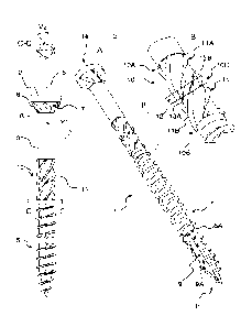
FIG. 1 illustrates a screw 1 in various views. The screw 1 comprises a screw-
head 2 at
a first end la of the screw and a shank 3 extending from the screw-head 2
towards an
opposite, second end lb of the screw 1. The screw-head 2 has a tapered surface
7,
exemplified as frusto-conical, towards the shank 3. On the underside of the
screw-
head 2, a plurality of milling-ribs 8 are provided on the tapered surface 7. A
thread 5
that extends from the second end lb is provided on the shank 3 for screwing
the screw
1 into a material.
In order for the screw 1 to cut its way easier into the material, the screw 1,
optionally,
comprises a cutting-edge 9 in the thread 5. The cutting-edge 9 extends along
the shaft
CA 03082155 2020-05-07
WO 2019/091536 PCT/D1(2018/050296
3 and is exemplified in FIG. 1 as a notch 9A extending over seven windings 5A
of the
thread 5 and with sharp edges. The notch 9A could extend over fewer or more
wind-
ings.
5 Furthermore, the screw 1 comprises a knurled region 10 on the shank 3 to
reduce drag
when the screw 1 is driven into the material, for example wood. Screwing into
wood
causes friction on the shank 3. By adding a knurled region, it mills a hole in
the wood
which is slightly larger in diameter than the shank, giving more space for the
shank 3
to penetrate into the wood. As illustrated in more detail in FIG. 3, the
knurled region
10 has an outer diameter D larger than the diameter d of the smooth shank 3
near the
screw-head 2 in order to create a hole wider than the shank 3.
A typical length of the knurled region relatively to the total length of the
screw is in
the range of 1-40%
Typically, the knurled region 10 is provided in immediate extension of the
thread 5.
With reference to FIG. 1, the knurled region has a first end 10A and an
opposite sec-
ond end 10B and a middle 10C midway between the first end 10A and the second
end
10B.
The knurled region 10 comprises a first set 11A of ribs 11 and a second set
11B of
ribs 11, the ribs 11 of both sets 11A, 11B are twisted helically around part
of the
shank 3 in the knurled region 10. The first set 11A of ribs 11 extend from the
first end
10A of the knurled region 10 towards the second end 10B and across the middle
10C
but not completely to the second end 10B of the knurled region 10. The second
set
11B of ribs 11 extends from the second end 10B towards the first end 10A of
the
knurled region 10 and across the middle 10C but not completely to the second
end
10B of the knurled region 10. As the ribs 11 from both sets 11A, 11B are
equally
long, this results in an overlap region 12 centered around the middle 10C of
the
knurled region 10.
It is pointed out, however, that the overlap region 12 can be centered closer
to the first
or the second end 10A, 10B.
CA 03082155 2020-05-07
WO 2019/091536 PCT/D1(2018/050296
6
The double set of ribs 11 with an overlapping region 12 has an advantage of an
in-
creased milling efficiency in wood and other fibrous material.
The first set 11A of ribs 11 is rotationally offset by an azimuth angle
(rotational angle)
corresponding to half the angular distance between the ribs 11. For example,
the first
set 11A of ribs 11 comprises four ribs 11 such that the angle between the ribs
is 90 .
The offset angle in this case is 45 . However, the number of ribs 11 can vary,
as illus-
trated when comparing the embodiment of FIG. 1 with four ribs 11 in each set
11A,
11B of ribs 11 with the embodiment of FIG. 2 with six ribs 11 in each set 11A,
11B of
ribs 11. In the latter case, the angle between neighboring ribs 11A is 60
degrees, why
the second set 11B of ribs 11 is rotationally offset by an azimuth angle of 30
degrees
relatively to the first 11A set of ribs 11. A typical number of ribs is in the
range of 3-
12.
In the side view drawing of FIG. 1, an angle V1 is indicated as a measure for
the angle
between the rib 11 and the central axis 6 of the screw 1. This helix angle is
typically
in the range of 20-75 for example in the range of 30-60 .
In the cross-section C-C in FIG. 1, the rib 11 is exemplified with a
triangular shape
having an angular span of V2. This angle V2 is typically in the range of 20-90
, for
example in the range of 30-80 , or even 40-70 .
As illustrated in FIG. 3, the width X1 of the overlap region 12 is
substantially shorter
than the entire length L of the knurled region 10 and shorter than even half
the length
L. The width X1 of the overlap region is measured from the respective ends
13A, 13B
of the intertwined ribs 11 in the first and second set 11A, 11B. In some
embodiments,
the width X1 is in the range of 3-30% of L.
In the exemplified embodiment, the overlap region 12 is centered at the middle
10C of
the knurled region 10. However, this is not strictly necessary. For example,
this over-
lap region 12 can be offset from the middle, for example by up to 25% of the
length of
CA 03082155 2020-05-07
WO 2019/091536 PCT/D1(2018/050296
7
L. However, typically, the offset is such that the ribs 11 from either set
11A, 11B do
not extend from one end to the opposite end 10A, 10B of the knurled region 10.
As illustrated in FIG. 3, the ribs 11 decrease in size in the overlap region
12. Also
illustrated are distances Li in which the ribs have constant thickness.