Note: Descriptions are shown in the official language in which they were submitted.
PCT/EP 2018/081 892 - 17.12.2019
CA 03082634 2020-05-14
1
AUTOMATED STORAGE AND RETRIEVAL SYSTEM (AMENDED)
Technical Field
The present invention relates to an automated storage and retrieval system, a
vehicle
for lifting and transporting storage containers stacked in stack within the
system and
a method thereof.
Background and prior art
Fig. 1 discloses a typical prior art automated storage and retrieval system 1
with a
framework structure 100 and Fig. 2 and 3 discloses two different prior art
container
handling vehicles 201,301 suitable for operating on such a system 1.
The framework structure 100 comprises a number of upright members 102 and a
number of horizontal members 103 which are supported by the upright members
102. The members 102, 103 may typically be made of metal, e.g. extruded
aluminum profiles.
The framework structure 100 defines a storage grid 104 comprising storage
columns
105 arranged in rows, in which storage columns 105 storage containers 106,
also
known as bins, are stacked one on top of another to form stacks 107. Each
storage
container 106 may typically hold a plurality of product items (not shown), and
the
product items within a storage container 106 may be identical, or may be of
different product types depending on the application. The storage grid 104
guards
against horizontal movement of the stacks 107 of storage containers 106, and
guides
vertical movement of the containers 106, but does normally not otherwise
support
the storage containers 106 when stacked.
The automated storage and retrieval system 1 comprises a rail system 108
arranged
in a grid pattern across the top of the storage columns 105, on which rail
system 108
a plurality of container handling vehicles 201,301 are operated to raise
storage
containers 106 from and lower storage containers 106 into the storage columns
105,
and also to transport the storage containers 106 above the storage columns
105. The
rail system 108 comprises a first set of parallel rails 110 arranged to guide
movement of the container handling vehicles 201,301 in a first direction X
across
the top of the frame structure 100, and a second set of parallel rails 111
arranged
perpendicular to the first set of rails 110 to guide movement of the container
handling vehicles 201,301 in a second direction Y which is perpendicular to
the first
direction X. In this way, the rail system 108 defines grid columns 112 above
which
the container handling vehicles 201,301 can move laterally above the storage
columns 105, i.e. in a plane which is parallel to the horizontal X-Y plane.
AMENDED SHEET
PCT/EP 2018/081 892 - 17.12.2019
CA 03082634 2020-05-14
2
Each prior art container handling vehicle 201,301 comprises a vehicle body
201a,301a, and first and second sets of wheels 201b,301b,201c,301c which
enable
the lateral movement of the container handling vehicles 201,301 in the X
direction
and in the Y direction, respectively. In Fig. 2 and 3 two wheels in each set
are fully
visible. The first set of wheels 201b,301b is arranged to engage with two
adjacent
rails of the first set 110 of rails, and the second set of wheels 201c,301c is
arranged
to engage with two adjacent rails of the second set 111 of rails. Each set of
wheels
201b,301b 201c,301c can be lifted and lowered, so that the first set of wheels
201b,301b and/or the second set of wheels 201c,301c can be engaged with the
respective set of rails 110, 111 at any one time.
Each prior art container handling vehicle 201,301 also comprises a lifting
device
(not shown) for vertical transportation of storage containers 106, e.g.
raising a
storage container 106 from, and lowering a storage container 106 into, a
storage
column 105. The lifting device comprises one or more gripping / engaging
devices
(not shown) which are adapted to engage a storage container 106, and which
gripping / engaging devices can be lowered from the vehicle 201,301 so that
the
position of the gripping / engaging devices with respect to the vehicle
201,301 can
be adjusted in a third direction Z which is orthogonal the first direction X
and the
second direction Y.
Conventionally, and also for the purpose of this application, Z=1 identifies
the
uppermost layer of the grid 104, i.e. the layer immediately below the rail
system
108, Z=2 the second layer below the rail system 108, Z=3 the third layer etc.
In the
embodiment disclosed in Fig. 1, Z=8 identifies the lowermost, bottom layer of
the
grid 104. Consequently, as an example, and using the Cartesian coordinate
system
X, Y, Z indicated in Fig. 1, the storage container identified as 106' in Fig.
1 can be
said to occupy grid location or cell X=10, Y=2, Z=3. The container handling
vehicles 201,301 can be said to travel in layer Z=0 and each grid column 112
can be
identified by its X and Y coordinates.
Each prior art container handling vehicle 201,301 comprises a storage
compartment
or space for receiving and stowing a storage container 106 when transporting
the
storage container 106 across the grid 104. The storage space may comprise a
cavity
arranged centrally within the vehicle body 201a as shown in Fig. 2 and as
described
in e.g. W02015/193278A1, the contents of which are incorporated herein by
reference.
Fig. 3 shows an alternative configuration of a container handling vehicles 301
with
a cantilever construction. Such a vehicle is described in detail in e.g.
NO317366,
the contents of which are also incorporated herein by reference.
AMENDED SHEET
PCT/EP 2018/081 892 - 17.12.2019
CA 03082634 2020-05-14
3
The central cavity container handling vehicles 201 shown in Fig. 2 may have a
footprint, i.e. an extent in the X and Y directions, which is generally equal
to the
lateral or horizontal extent of a grid column 112, i.e. the extent of a grid
column
112 in the X and Y directions, e.g. as is described in W02015/193278A1, the
contents of which are incorporated herein by reference.
Alternatively, the central cavity container handling vehicles 101 may have a
footprint which is larger than the lateral extent of a grid column 112, e.g.
as is
disclosed in W02014/090684A1.
The rail system 108 may be a single rail system, as is shown in Fig. 4.
Alternatively, the rail system 108 may be a double rail system, as is shown in
Fig. 5, thus allowing a container handling vehicle 201,301 having a footprint
generally corresponding to the lateral extent of a grid column 112 to travel
along a
row of grid columns even if another container handling vehicle 101 is
positioned
above a grid column neighboring that row. Both the single and double rail
system
forms a grid pattern in the horizontal plane P comprising a plurality of
rectangular
and uniform grid locations or grid cells 122, where each grid cell 122
comprises a
grid opening 115 being delimited by a pair of tracks 110a, 110b of the first
tracks
110 and a pair of tracks 111a,111b of the second set of tracks 111. In Fig. 5
the grid
cell 122 is indicated by a dashed box.
Each grid cell 122 has a width which is typically within the interval of 30 to
150
cm, and a length which is typically within the interval of 50 to 200 cm. Each
grid
opening 115 has a width and a length which is typically 2 to 10 cm less than
the
width and the length of the grid cell 122.
In a storage grid 104, a majority of the grid columns 112 are storage columns
105,
i.e. grid columns 105 where storage containers 106 are stored in stacks 107.
However, a grid 104 normally has at least one grid column 112 which is used
not
for storing storage containers 106, but which comprises a location where the
container handling vehicles 201,301 can drop off and/or pick up storage
containers
106 so that they can be transported to an access station (not shown) where the
storage containers 106 can be access from outside of the grid 104 or
transferred out
of or into the grid 104. Within the art, such a location is normally referred
to as a
'port' and the grid column 112 in which the port is located may be referred to
as a
port column 119,120.
The grid 104 in Fig. 1 comprises two port columns 119 and 120. The first port
column 119 may for example be a dedicated drop-off port column where the
container handling vehicles 201,301 can drop off storage containers 106 to be
transported to an access or a transfer station, and the second port column 120
may
be a dedicated pick-up port column where the container handling vehicles
201,301
AMENDED SHEET
PCT/EP 2018/081 892 - 17.12.2019
CA 03082634 2020-05-14
4
can pick up storage containers 106 that have been transported to the grid 104
from
an access or a transfer station.
The access station may typically be a picking or a stocking station where
product
items are removed from or positioned into the storage containers 106. In a
picking
or a stocking station, the storage containers 106 are normally never removed
from
the automated storage and retrieval system 1, but are returned into the grid
104 once
accessed. A port can also be used for transferring storage containers out of
or into
the grid 104, e.g. for transferring storage containers 106 to another storage
facility
(e.g. to another grid or to another automated storage and retrieval system),
to a
transport vehicle (e.g. a train or a lorry), or to a production facility.
A conveyor system comprising conveyors is normally employed to transport the
storage containers between the ports 119,120 and the access station.
If the ports 119,120 and the access station are located at different levels,
the
conveyor system may comprise a lift device with a vertical component for
transporting the storage containers 106 vertically between the port 119,120
and the
access station.
The conveyor system may be arranged to transfer storage containers 106 between
different grids, e.g. as is described in W02014/075937A1, the contents of
which are
incorporated herein by reference.
When a storage container 106 stored in the grid 104 disclosed in Fig. 1 is to
be
accessed, one of the container handling vehicles 201,301 is instructed to
retrieve the
target storage container 106 from its position in the grid 104 and transport
it to the
drop-off port 119. This operation involves moving the container handling
vehicle
201,301 to a grid location above the storage column 105 in which the target
storage
container 106 is positioned, retrieving the storage container 106 from the
storage
column 105 using the container handling vehicle's 201,301 lifting device (not
shown), and transporting the storage container 106 to the drop-off port 119.
If the
target storage container 106 is located deep within a stack 107, i.e. with one
or a
plurality of other storage containers 106 positioned above the target storage
container 106, the operation also involves temporarily moving the above-
positioned
storage containers prior to lifting the target storage container 106 from the
storage
column 105. This step, which is sometimes referred to as "digging" within the
art,
may be performed with the same container handling vehicle that is subsequently
used for transporting the target storage container to the drop-off port 119,
or with
one or a plurality of other cooperating container handling vehicles.
Alternatively, or
in addition, the automated storage and retrieval system 1 may have container
handling vehicles specifically dedicated to the task of temporarily removing
storage
containers from a storage column 105. Once the target storage container 106
has
AMENDED SHEET
PCT/EP 2018/081 892 - 17.12.2019
CA 03082634 2020-05-14
been removed from the storage column 105, the temporarily removed storage
containers can be repositioned into the original storage column 105. However,
the
removed storage containers may alternatively be relocated to other storage
columns.
When a storage container 106 is to be stored in the grid 104, one of the
container
5 handling vehicles 201,301 is instructed to pick up the storage container
106 from
the pick-up port 120 and transport it to a grid location above the storage
column 105
where it is to be stored. After any storage containers positioned at or above
the
target position within the storage column stack 107 have been removed, the
container handling vehicle 201,301 positions the storage container 106 at the
desired position. The removed storage containers may then be lowered back into
the
storage column 105, or relocated to other storage columns.
For monitoring and controlling the automated storage and retrieval system 1,
e.g.
monitoring and controlling the location of respective storage containers 106
within
the grid 104, the content of each storage container 106; and the movement of
the
container handling vehicles 201,301 so that a desired storage container 106
can be
delivered to the desired location at the desired time without the container
handling
vehicles 201,301 colliding with each other, the automated storage and
retrieval
system 1 comprises a control system which typically is computerized and which
typically comprises a database for keeping track of the storage containers
106.
W02016/120075A1, the contents of which are incorporated herein by reference,
shows an example of an automated storage and retrieval system using vehicles
with
a central cavity. The disclosed container handling vehicles are dimensioned so
that
they have a footprint, i.e. a contact area against the track system, which has
a
horizontal extent that is equal to the horizontal extent of a grid cell.
Within the art,
such a container handling vehicle, i.e. a container handling vehicle having a
footprint with a horizontal extent corresponding to the horizontal extent of a
single
grid cell, is sometimes referred to as a "single cell" container handling
vehicle.
Another single cell container handling vehicle is disclosed in
W02015/193278A1,
the contents of which are incorporated herein by reference.
The single cell design disclosed in e.g. W02016/120075A1 and W02015/193278A1
reduces the space required for the container handling vehicles to travel on
the track
system, thus allowing more vehicles to operate on the track system without
interfering with each other. Further, the stability of the vehicle operation
is
increased compared to a cantilever vehicle as disclosed in e.g. NO317366.
A problem with prior art automated storage and retrieval systems using storage
container vehicles with single cell design is that these vehicles necessitate
a vehicle
body having a container receiving cavity that must be open towards the
underlying
storage grid. Strict space constraints are therefore set as to the locations
and sizes of
AMENDED SHEET
PCT/EP 2018/081 892 - 17.12.2019
CA 03082634 2020-05-14
6
necessary vehicle components, e.g. lifting devices and wheel displacement
means.
To maximize the horizontal cross section of the cavity, at least some of the
vehicle
components of the prior art single cell vehicles are arranged above the cavity
(see
e.g. WO 2015/193278 Al) and/or within the wheels (see e.g. WO 2016/120075 Al),
a solution that results in high complexity and cost compared with the earlier
cantilever vehicle design disclosed in NO317366. Moreover, to minimize the
height
and the total weight of the vehicle, the size of components such as motors and
batteries should in the 'single cell' vehicles be minimized in size and/or
restricted to
light weight materials, criteria that limit the maximum achievable operation
efficiency of the vehicle such as the maximum lifting power available for the
storage container lifting device. Bulky components may be arranged above the
cavity by increasing the total height of the vehicle. However, such an
increased
height would result in an undesired decrease in overall vehicle stability in
addition
to increased cost.
The cantilever vehicle disclosed in N0317366 may contain components such as
motor and batteries being considerably larger than the 'single cell' vehicle.
But the
cantilever vehicles have the disadvantage of protruding beyond the footprint
of the
vehicle, i.e. into a neighboring grid cell. This will prevent other container
handling
vehicles from operating on the neighboring grid cell, thus limiting the space
available for other container handling vehicles to operate on the track
system. Due
to the cantilever design, these prior art vehicles have the additional
disadvantage
that they may lift storage containers from one direction in the horizontal
plane only,
thereby necessitating a high degree of maneuvering on the track system during
'digging' operations and transport to port. Moreover, the cantilever design
forces
these vehicles to ports and/or boundary grid columns arranged at one
particular side
of the storage grid, thereby further reducing the overall efficiency of the
system.
From prior art one should also refer to:
US2008/075569 Al related to a system and method for the safe storage of items
wherein a storage structure is provided having a first section in which
storage units
are stored in vertically oriented cells with each storage unit being stacked
one upon
another and wherein at least one transfer vehicle is provided for selectively
engaging and conveying the storage units along an overhead grid track system
between the first section and a second section wherein the at least one
transfer
vehicle may be used to either lift or lower a storage unit and move the
storage unit
to and from a storage position in one of the vertical storage cells of the
first section
of the storage structure.
EP 3192751 Al relates to a temporary storage system having a large capacity
and
loading and unloading articles promptly is provided. The temporary storage
system
AMENDED SHEET
PCT/EP 2018/081 892 - 17.12.2019
CA 03082634 2020-05-14
7
has a grid-like travelling rail and buffers over processing equipment except
for an
area over a load port, and local vehicles travel along the rail. The carriage
of the
local vehicles is provided with at least a longitudinal travelling unit, at
least a
lateral travelling unit, and at least an advancement and retraction mechanism
selectively advancing one of the longitudinal travelling unit and the lateral
travelling unit to a position supported by the travelling rail, and travels
along the
travelling rail longitudinally and laterally, and the transfer unit of the
local vehicles
is provided with a hoist and an arm moving the hoist horizontally. The local
vehicles stop at a position corresponding to the load port, advances the arm
towards
the load port, and transfers an article between the load port.
WO 2017/148939 Al relates to a robotic service device (50) is described for
use on
a robotic picking system grid. The robotic service device (50) is capable of
driving
to any location on the grid (14) in order to restart malfunctioning robotic
load
handling devices (30) or to perform maintenance operations or cleaning in
situ.
Additionally, the service device 50 may be used to rescue robotic load
handling
devices (30) operational in the picking system. The robotic service device
(50) may
comprise a releasable docking mechanism 58 to enable it to dock and latch on
to
malfunctioning load handling devices (30). The service device (50) may also be
provided with cleaning means and camera means to enable the condition of the
grid
(14) and other robotic devices to be monitored.
US 2017/121109 Al relates to a stack operating vehicle for storage and
retrieval
storage units. One embodiment of the stack operating vehicle comprises a first
bearing device with a first bearing base and a first holding device for
handling at
least one storage unit; a second bearing device with a second bearing base and
a
second holding device for handling at least one storage unit. The second
holding
device is movably supported by a guiding device along a horizontal direction;
a
vertical guide arrangement at which the first bearing base and the second
bearing
base are respectively guided on an adjustment path along the vertical
direction
which are formed such that the first bearing base and the second bearing base
overlap one another over their entire adjustment paths in the vertical
direction. The
disclosure also relates to a method for execution of storage orders with
storage units
with such a stack operating vehicle.
WO 2017/081281 Al relates to a system for picking items 28 from a
containerised
storage system is described. The items 28 are stored in storage bins 10 in
stacks 12
within a framework 14 comprising a grid system 22 disposed above the stacks 12
of
bins 10. Robotic devices 30 are disposed on the grid 22, the devices acting so
as to
pick containers from the stacks 12 of bins 10. The storage system is provided
with
at least one picking device for picking items 28 from bins 10 and depositing
them
directly in delivery containers DT.
AMENDED SHEET
PCT/EP 2018/081 892 - 17.12.2019
CA 03082634 2020-05-14
8
WO 98/55381 Al relates to A device has lift arms (42) with links (46, 46D)
connected to the ends of a loadspreader (40) or the links (46, 46D) swivelly
connected to the lift arms (42) and aligned to hook special containers (20D).
The lift
arms (42) are pivotally connected to a hub (44, 44B) to swing vertically. Each
hub
is mounted to rotate on a vertical support shaft (38) central between the ends
of the
loadspreader (40) or hooking and lifting links (46, 46D) for each end of a
load. A
hydraulic cylinder (48) connects each lift arm to its hub to lift and lower
the arms
(42) together to lift and lower the loadspreader (40) substantially level. The
hubs
(44, 44B) can be rotated relatively horizontally to move the loadspreader (40)
sidewise parallel and/or turn it to align a load. A rotary crane (18) carries
the lift
linkage about a support pivot with parallel positioning control to translate
the
loadspreader over a circular area and with control to extend or retract the
loadspreader sideways.
In view of the above, it is desirable to provide a vehicle operating on an
automated
storage and retrieval system, and a method thereof, that solves or at least
mitigates
one or more of the aforementioned problem related to use of prior art storage
and
retrieval systems.
Summary of the invention
The present invention is set forth and characterized in the main claims, while
the
dependent claims describe other characteristics of the invention.
In particular, the invention concerns an automated storage and retrieval
system
comprising a track system comprising a first set of parallel tracks arranged
in a
horizontal plane (P) and extending in a first direction (X) and a second set
of
parallel tracks arranged in the horizontal plane (P) and extending in a second
direction (Y) which is orthogonal to the first direction (X). The first and
second sets
of tracks form a grid pattern in the horizontal plane (P) comprising a
plurality of
adjacent grid cells, each comprising a grid opening defined by a pair of
neighboring
tracks of the first set of tracks and a pair of neighboring tracks of the
second set of
tracks. The system further comprises a plurality of stacks of storage
containers
arranged in storage columns located beneath the track system, wherein each
storage
column is located vertically below a grid opening and one or more vehicles,
each
comprising a storage container lifting device for lifting and lowering storage
containers stacked in the stacks, a drive system comprising a wheel
arrangement, a
base / Base onto which the wheel arrangement is connected, a rotational part
rotationally connected via a swivel device to the base having a rotational
axis (R)
preferably directed perpendicular to the horizontal plane (P) and preferably a
rotational drive system for rotating the rotational part relative to the base.
The
drive system is configured to drive the vehicle along the track system in the
first
AMENDED SHEET
PCT/EP 2018/081 892 - 17.12.2019
CA 03082634 2020-05-14
9
direction (X), the second direction (Y) or both. The storage container lifting
device
is preferably connected to the rotational part.
The vehicle may advantageously also comprise one or more registration devices
configured for acquiring any information related to content / items within a
storage
container situated on top of a stack during operation, for example any
recording
device such as a camera that allows acquisition of live and/or still images of
contents within any storage containers. The registration device should be
arranged
such that free sight towards the track system is ensured at least part of the
operational time of the vehicle, for example when the vehicle is void of any
storage
containers.
Alternatively, or in addition, the vehicle may further comprise one or more
dedicated registration devices for acquiring data related to the position of
the
vehicle relative to the track system during operation. As for the registration
device(s) for the content of the storage containers, positional registration
device(s)
should also be arranged on the vehicle such that free sight towards the track
system
is ensured at least part of vehicle's operational time. Example of locations
for both
type of registration devices is on the rotational part and/or the base and/or
the wheel
arrangement. A registration device is herein defined as any device that may
acquire
positional and/or visual information of the environment surrounding the
vehicle.
The possibility to rotate the rotational part relative to the base and the
wheel
arrangements increases the possible registration / sweeping area of the
vehicle.
The rotational part preferably further comprises a bulk section rotationally
connected to the base and a protruding section extending horizontally in the
first
direction (X) from the bulk section to form a container receiving space
confined in
height by the vertical distance from the track system to the protruding
section and in
the horizontal plane (P) to the horizontal extent of the protruding section.
In this
particular configuration, the storage container lifting device is arranged at
least
partly below the protruding section. The above-mentioned registration
device(s)
may for this design be arranged on the sides and/or beneath the protruding
section,
for example connected to the storage container lifting device. The latter
exemplary
position is particularly relevant in case of registration device(s) such as a
camera
allowing live and/or still images of content within a storage container.
In addition to a protruding section extending horizontally in the first
direction (X)
from the bulk section the vehicle may also in another embodiment comprise a
second protruding section extending horizontally in the first direction (X)
from the
bulk section opposite of the first protruding section, forming a second
container
receiving space with the same confined in height and in the horizontal plane
(P) as
for the first container receiving space. As for the first protruding section,
the
storage container lifting device may be arranged at least partly beneath the
second
AMENDED SHEET
PCT/EP 2018/081 892 - 17.12.2019
CA 03082634 2020-05-14
protruding section. This particular embodiment including two or more
protruding
sections enables handling of a plurality of storage containers in each
operation,
thereby increasing the rate storage containers may be handled relative to the
above
mentioned prior art vehicles with cantilever design or 'single cell' design
when
5 operating the above-mentioned storage and retrieval system.
In an advantageous configuration the drive system comprises a first wheel
arrangement configured to guide the vehicle along the track system in the
first
direction (X). The first wheel arrangement comprises preferably four wheels or
two
belts arranged with their rotational axes in the second direction (Y).
Further, in
10 order to increase the overall stability of the vehicle during operation,
i.e. transport
and storage container handling, the first wheel arrangement may have a length
in
the first direction (X) that is longer than the distance between a pair of
neighboring
track of the second set of tracks.
However, such an increased stability may also be achieved by adding additional
weight to the bulk section. The latter alternative may be preferable in order
keep the
drive system within a footprint of grid cell, thereby allowing other vehicles
to pass
on all neighboring grid cells if there is synchronized rotation of the
rotational part.
For example, when a vehicle is approaching a neighboring grid cell into which
another vehicle's protruding section is extended, the rotational part of the
latter
vehicle may rotate at least 90 in order to clear the drive path of the former
vehicle.
The drive system may further comprise a second wheel arrangement configured to
guide the vehicle along the track system in the second direction (Y). As for
the first
wheel arrangement, the second wheel arrangement comprises preferably four
wheels
or two belts arranged with their rotational axes in the first direction (X).
The second
wheel arrangement have preferably a length in the second direction (Y) being
equal
or shorter than the distance between a pair of neighboring track of the first
set of
tracks.
In another advantageous configuration the vehicle further comprises a
replaceable
power source coupled to the rotational part, for example a replaceable power
source
with a corresponding charging station as described and illustrated in patent
publication WO 2015/104263 A2.
The invention also concerns a vehicle suitable for lifting and transporting
storage
containers stacked in stacks within the above disclosed automated storage and
retrieval system. The inventive vehicle is configured to move on the track
system
above the storage columns and comprises a storage container lifting device for
lifting storage containers stacked in the stacks, a drive system comprising a
wheel
arrangement, a base onto which the wheel arrangement is connected, a
rotational
part rotationally connected via a swivel device to the base and a rotational
drive
system for rotating the rotational part relative to the base. The drive system
is
AMENDED SHEET
PCT/EP 2018/081 892 - 17.12.2019
CA 03082634 2020-05-14
11
configured to drive the vehicle along the track system in at least one of the
first
direction (X) and the second direction (Y).
The invention also concerns a method of operating an automated storage and
retrieval system as described above, where method comprises the steps of:
- selecting/identifying, by for example entering one or more particular
items in
a dedicated software, a target storage container within a target storage
column
comprising the target storage container with the particular item(s) and at
least one
non-target storage container,
- operating the drive system to maneuver the vehicle in the
horizontal plane
(P) such that the storage container lifting device is arranged directly above
the grid
opening of the target storage column into which the selected target storage
container
is arranged,
- lifting the topmost storage container of the target storage column
fully above
the track system by use of the storage container lifting device.
If the topmost storage container is identified as a non-target storage
container, the
method further comprises the steps of:
- locating an available non-target storage column within the system
onto or
into which the non-target storage container may be arranged and
- arranging the storage container lifting device with the non-target
storage
container directly above the grid opening of the non-target storage column by
operating the drive system to maneuver the vehicle in the horizontal plane (P)
or
operating the rotational drive system to rotate the rotational part relative
to the base
or a combination thereof and
- repeating the method steps involving the non-target storage
container until
the topmost storage container of the target storage column is the selected
target
storage container.
When the topmost storage container is identified as the target storage
container, the
method further includes transporting the topmost storage container, i.e. the
target
storage container, to a drop-off port within or adjacent to the track system.
In the following, numerous specific details are introduced by way of example
only
to provide a thorough understanding of embodiments of the claimed system,
vehicle
and method. One skilled in the relevant art, however, will recognize that
these
embodiments can be practiced without one or more of the specific details, or
with
other components, systems, etc. In other instances, well-known structures or
operations are not shown, or are not described in detail, to avoid obscuring
aspects
of the disclosed embodiments.
Brief description of the drawings
AMENDED SHEET
PCT/EP 2018/081 892 - 17.12.2019
CA 03082634 2020-05-14
12
Following drawings are appended to facilitate the understanding of the
invention.
Fig. 1 is a perspective view of a grid of a prior art automated storage and
retrieval
system.
Fig. 2 is a perspective view of a prior art container handling vehicle having
a
centrally arranged cavity for containing storage containers therein.
Fig. 3 is a perspective view of a prior art container handling vehicle having
a
cantilever for containing storage containers underneath.
Fig. 4 is a top view of a prior art single rail grid.
Fig. 5 is a top view of a prior art double rail grid.
Figs. 6 (a)-(c) shows in a perspective view, a side view and a top view,
respectively, a
container handling vehicle of a first embodiment of the invention operating on
double rail
grid cells of an automated storage and retrieval system.
Fig. 7 is a side view of the storage container filled automated storage and
retrieval
system seen along the X direction, where two container handling devices as
shown
in Fig. 6 are arranged side by side on double rail grid cells.
Figs. 8 (a)-(c) shows the container handling vehicle of Figs. 6 and 7 in a
perspective
view, a side view and a top view, respectively, where the rotational part of
the container
handling vehicle has been rotated 180 .
Fig. 9 is an exploded perspective view of the container handling vehicle of
Fig. 6-8.
Fig. 10 is a perspective view of the container handling vehicle of Fig. 6-9,
wherein the
rotational part of the container vehicle has been rotated 45 .
Fig. 11 is a perspective view of the container handling vehicle of Fig. 6-10,
wherein a
lifting device of the container handling vehicle has been lowered into a
storage column of
an automated storage and retrieval system
Figs. 12 (a)-(c) show in a perspective view, a side view and an end view,
respectively, a
container handling vehicle of a second embodiment of the invention operating
on double
rail grid cells of an automated storage and retrieval system.
Figs. 13 (a)-(b) are perspective views from two different angles of a
container handling
vehicle of a third embodiment of the invention.
Figs. 14 (a)-(b) are side views of the container handling vehicle in Fig. 12
seen along the
Y direction and the X direction, respectively.
AMENDED SHEET
PCT/EP 2018/081 892 - 17.12.2019
CA 03082634 2020-05-14
13
Fig. 15 is an exploded perspective view of a lifting device capable of lifting
a single
storage containers in one lifting operation.
Fig. 16 is a perspective view of a lifting device capable of lifting a
plurality of storage
containers in one lifting operation.
In the drawings, like reference numerals have been used to indicate like
parts, elements
or features unless otherwise explicitly stated or implicitly understood from
the context.
Detailed description of the invention
In the following, embodiments of the invention will be discussed in more
detail by
way of example only and with reference to the appended drawings. It should be
understood, however, that the drawings are not intended to limit the invention
to the
subject-matter depicted in the drawings.
If not otherwise stated, the framework 100 of the automated storage and
retrieval
system 1 is constructed in accordance with the prior art framework 100
described
above in connection with Figs. 1-5, i.e. a number of upright members 102 and a
number of horizontal members 103 which are supported by the upright members
103, and further that the framework 100 comprise the track system 108 of
parallel
tracks 110,111 in X direction and Y direction arranged across the top of
storage
columns 105 / grid columns 112. The horizontal area of a grid column 112, i.e.
along the X and Y directions, may be defined by the distance between adjacent
rails
110 and 111, respectively (see also Fig. 4 and 5).
In Fig. 1 the grid 104 is shown with a height of eight cells. It is
understood,
however, that the grid 104 in principle can be of any size. In particular it
is
understood that grid 104 can be considerably wider and/or longer and/or deeper
than
disclosed in Fig. 1. For example, the grid 104 may have a horizontal extent of
more
than 700x700 grid cells and a depth of more than twelve grid cells.
One embodiment of a container handling vehicle 3 according to the invention
will
now be discussed in more detail with reference to Figs. 6 to 9.
Each container handling vehicle 3 comprises a rotational part 30 rotationally
coupled onto a base 31 via a swivel device 32. A drive system 18 is fixed to
the
base 3 enabling lateral/horizontal movement of the container handling vehicle
3, i.e.
the movement of the vehicle 3 in the X and Y directions on the track system
108 of
the storage grid 104.
The drive system 18 comprises a first set of wheels 19 arranged to engage with
a
pair of tracks 110a,110b of the first set of tracks 110, and a second set of
wheels 20
arranged to engage with a pair of tracks 111a,111b of the second set of tracks
111
AMENDED SHEET
PCT/EP 2018/081 892 - 17.12.2019
CA 03082634 2020-05-14
14
(see Figs. 4 and 5). At least one of the set of wheels 19, 20 can be lifted
and
lowered so that the first set of wheels 19 and/or the second set of wheels 20
can be
brought to engage with the respective set of tracks 110, 111 at any one time.
Each set of wheels 19,20 comprises four wheels 19a, 19b, 19c, 19d; 20a, 20b,
20c,
20d arranged along the sides of the vehicle 3. Wheels 19a and 19b are arranged
in a
first vertical plane, and wheels 19c and 19d are arranged in a second vertical
plane
which is parallel to the first vertical plane and arranged at a distance from
the first
vertical plane which corresponds to the distance between rails 110a and 110b.
Wheels 20a and 20b are arranged in a third vertical plane, which is orthogonal
to
the vertical planes in which wheels 19a-19d are arranged, and wheels 20c and
20d
are arranged in a fourth vertical plane which is parallel to the third
vertical plane
and arranged at a distance from the third vertical plane which corresponds to
the
distance between rails 111a and 111b.
At least one of the wheels in each set 19, 20 may be motorized in order to
propel the
vehicle 3 along the track system 108. At least one motorized wheel in each set
may
include a hub motor, i.e. an electric motor that is coupled to, or
incorporated into,
the hub of a wheel and which drives the wheel directly. An example of a
container
handling vehicle with such a motor is disclosed in W02016/120075A1, the
contents
of which are incorporated herein by reference. In an alternative example, at
least
one of the wheels 19a-d;20a-d is a passive wheel propelled by one or more
motors
situated within the base 31 and/or the rotational part 30 and/or the swivel
device 32
of the vehicle 3. A drive system 18 involving a combination of hub motor(s)
and
external situated motor(s) may also be envisaged.
Each rotational part 30 comprises a bulk section 30b and a protruding section,
hereinafter called cantilever 30a, extending horizontally in the X direction.
In the
particular embodiment shown in Figs. 6-9 the cantilever 30a is formed by
fixing
cantilever beams 30c onto each vertical sides of a vehicle framework 30d at or
near
the vehicles 3 uppermost part. Both the vehicle framework 30d, constituting
part of
the rotational part 30, and the cantilever beams 30c are covered by two
parallel
vertical side covers 39 oriented along the direction of the cantilever beams
30c, a
vertical front cover 37 oriented perpendicular to the direction of the
cantilever
beams 30b, a vertical back cover 38 oriented perpendicular to the direction of
the
cantilever beams 30c covering the rotational part 30 below the cantilever 30a
and a
horizontal top cover 36 covering the entire footprint of the vehicle 3, i.e.
the
horizontal extent of the vehicle 3 seen from above.
The bulk section 30b may contain bulky components such as a vehicle battery
40, a
control panel 35, and any motors 15a operating the vehicle 3.
AMENDED SHEET
PCT/EP 2018/081 892 - 17.12.2019
CA 03082634 2020-05-14
The vehicle battery 40 may be fixed into the bulk section 30b by fastening
means.
Further, the vehicle 3 may include a charging socket 41 coupled to the battery
40 in
order to allow battery recharging at a dedicated charging station within the
automated storage and retrieval system 1. Alternatively, or in addition, the
vehicle 3
5 may be equipped with a replaceable battery 40, for example a replaceable
battery
having a corresponding battery slot 40a within the vehicle 3, for example
within the
bulk section 30b, and a battery opening 40b having a size allowing the
replaceable
battery 40 to be guided through. The battery opening 40b is for example in the
front
cover 37. The corresponding charging stations and the battery exchange
10 mechanisms may be the same as the charging stations and exchange
mechanisms as
disclosed in the international patent publication WO 2015/104263, which
contents
are incorporated herein by reference. Particular reference is made to the
disclosure
of the battery exchange mechanism in WO 2015/104263 referring to Figs. 7-9.
Since the bulk section 30b of the rotational part 30 does not need to allocate
any
15 space for a storage container 106, the design of the vehicle 3 allows
larger batteries
to be mounted/coupled in/to the vehicle 3.
The rotation part 30 comprises a storage container lifting device 16 arranged
within
and/or below the cantilever 30a for vertical transportation of a storage
container
106, e.g. lifting a storage container 106 from a storage column 105 and
bringing it
to a position in a container receiving space 33 between the underlying rail
system
108 and the cantilever 30a, and also for lowering a storage container 106 from
the
container receiving space 33 into a storage column 105. The lifting device 16
comprises one or more lifting shafts 15 connected to one or more lifting
motors 15a
ensuring rotational power to the lifting shafts 15, one or more lifting belts
14
rotationally attached to the lifting shaft 15 and a lifting plate 13 attached
at its upper
face to the end of the lifting belts 14 not attached to the respective lifting
shaft 15.
The lifting shafts 15, the lifting motors 15a and the lifting belts 14 are
configured to
allow winding on to/out from the lifting shaft 15 during operation by the
lifting
motors 15a, thereby allowing lifting and lowering of the lifting plate 13,
i.e.
adjusting the lifting plate 13 in a third direction Z which is orthogonal to
the first
direction X and the second direction Y. The lifting device 16 further
comprises one
or more engagement devices or gripping devices 12 and one or more guiding pins
17 arranged at the lower face of the lifting plate 13. The engagement devices
12 are
configured to grip or engage the storage container 106 for lifting / lowering,
and the
guiding pins 17 are configured to ensure sufficiently accurate positioning of
the
lifting device 16 in respect of the storage container 106 during lifting /
lowering
operations.
In the embodiment shown in Figs. 6-9 the lifting device 16 comprises two
lifting
shafts 15 arranged within the cantilever 30a in the direction of the
cantilever beams
AMENDED SHEET
PCT/EP 2018/081 892 - 17.12.2019
CA 03082634 2020-05-14
16
30b at or near each vertical sides of the vehicle, two lifting belts 14
arranged at or
near the ends of each lifting shafts 15 for allowing winding thereon and where
the
ends of each belt 14 distal to the lifting shafts 15 is attached at or near
the four
corners on the upper face of the lifting plate 13. Each lifting shaft 15 is
operated by
a dedicated lifting motor 15a arranged within the rotational part 30 outside
the
cantilever 30a. The lifting shafts 15 may also be arranged immediately above
and/or
beneath the cantilever 30a.
Conventionally, and also for the purpose of this application, Z=1 identifies
the
uppermost layer of the storage grid, i.e. the layer immediately below the
track
system 10, Z=2 the second layer below the track system 10, Z=3 the third layer
etc.
The container handling vehicles 3 can be said to travel in layer Z=0.
Consequently,
each storage column can be identified by its X and Y coordinates, and each
storage
position in the storage grid can be identified by its X, Y and Z coordinates.
When a storage container 106 stored in the storage grid 104 is to be accessed,
one
of the container handling vehicles 3 is instructed to retrieve the target
storage
container 106 from its position in the storage grid 104 and to transport the
target
storage container 106 to an access station (not shown) where it can be access
from
outside of the storage grid 104 or transferred out of the storage grid 104.
This
operation involves moving the container handling vehicle 3 to a position where
the
cantilever 30a is positioned directly above a grid opening 115 of a storage
column
105 in which the target storage container 106 is positioned and retrieving the
storage container 106 from the storage column 105 using the container handling
vehicle's lifting device 16. This step involves using the lifting device 16 to
lift the
storage container 106 from the storage column 105 through the grid opening 115
and into the container receiving space 33 of the vehicle 3.
If the target storage container 106 is located deep within a stack 107, i.e.
with one
or a plurality of other storage containers positioned above the target storage
container 106, the operation also involves temporarily moving the above-
positioned
storage containers prior to lifting the target storage container 106 from the
storage
column 105. This step, which is sometimes referred to as "digging" within the
art,
may be performed with the same container handling vehicle 3 that is
subsequently
used for transporting the target storage container 106 to the access station,
or with
one or a plurality of other cooperating container handling vehicles.
Alternatively, or
in addition, the automated storage and retrieval system 1 may have container
handling vehicles specifically dedicated to the task of temporarily removing
storage
containers from a storage column. Once the target storage container 106 has
been
removed from the storage column 105, the temporarily removed storage
containers
can be repositioned into the original storage column 105. However, the removed
storage containers may alternatively be relocated to other storage columns.
AMENDED SHEET
PCT/EP 2018/081 892 - 17.12.2019
CA 03082634 2020-05-14
17
Once the target storage container 106 has been brought into the container
receiving
space 33 of the container handling vehicle 3 immediately below or partly into
the
cantilever 30a, the vehicle 3 transports the storage container 106 to the
access
station where it is unloaded. The access station may typically comprise a grid
location at the periphery of the storage grid 104 where the storage container
106 can
be accessed manually or transported further using a suitable conveyor system.
When a storage container 106 is to be stored in the storage grid 104, one of
the
container handling vehicles 3 is instructed to pick up the storage container
106 from
a pick-up station (not shown), which may also double as an access station, and
transport it to a grid opening 115 above the storage column 105 where it is to
be
stored. After any storage containers positioned at or above the target
position within
the storage column stack 107 have been removed, the container handling vehicle
3
positions the storage container 106 at the desired position. The removed
storage
containers may then be lowered back into the storage column 105, or relocated
to
other storage columns within the storage grid 104.
The cantilever 30a and/or the suspended lifting device 16 may also hold one
more
sensors 21 and/or one or more cameras 21, preferably down-looking sensors 21
and/or cameras 21. The sensors may be used to establish the position of the
vehicle
on the track system 108, e.g. the alignment of the vehicle vis-à-vis a grid
opening
115 or to establish the position of the vehicle 3 vis-à-vis other vehicles on
the track
system 108, e.g. when operating the vehicles as a train of vehicles, an
operation
considered beneficial for a cantilever type vehicle with a rotational part
since a train
of vehicles may be easily formed with a uniform direction of the cantilevers
by
simple rotations.
A camera opens up additional possibilities such as visual inspection of the
contents
within a storage container, which images may be sent to the user / customer
via the
control system. Hence, when searching for one or more specific items, the user
and/or customer may have access to an image of the position, orientation and
size
within a storage container 106. The sensors and/or cameras may be arranged on
the
lower face of the cantilever 30a such that free sight to the underlying track
system
is ensured, at least part of the operational time. Further, the cameras may
alternatively, or in addition, be arranged on the storage container lifting
device 16
enabling free sight into at least the topmost storage container 106 within a
storage
column 105. The ability to rotate the rotational part 30 further increases the
usability of said sensors or cameras since it enables sweeping over larger
areas
within the system 1.
Of course, one or more cameras and/or sensors may be mounted elsewhere on the
vehicle 3, for example in order to gain information of zones along and/or
above the
AMENDED SHEET
PCT/EP 2018/081 892 - 17.12.2019
CA 03082634 2020-05-14
18
framework 100. For example, a camera may be mounted on top of the vehicle 3
and/or on an antenna of the vehicle 3.
Fig. 15 shows an example of a lifting device 16 comprising a lifting plate 13,
a
plurality of gripping devices 12 for gripping / engaging with a storage
container 106
and a plurality of guiding pins 17 for aligning the lifting device 16 with the
storage
container 106. The lifting plate 13 further comprises a top cover 13a, a base
cover
13b and one or more cameras 21 installed on the lifting plate 13, preferably
within
the base cover 13b. The one or more cameras 12 are configured to record and
register images of products arranged below the lifting device 16, i.e. into
the
framework structure 100 and underlying storage containers 106.
For monitoring and controlling the automated storage and retrieval system 1 so
that
a desired storage container 106 can be delivered to the desired location at
the
desired time without the container handling vehicles 3 colliding with each
other, the
automated storage and retrieval system comprises a control system (not shown),
which typically is computerized and comprises a database for monitoring and
controlling e.g. the location of the respective storage containers 106 within
the
storage grid 104, the content of each storage container 106 and the movement
of the
container handling vehicles 3.
The container handling vehicles 3 typically communicates with the control
system
from a control panel 35, typically arranged on top of the vehicle 30 as shown
in
Figs. 6-9, via wireless communication means, e.g. via a WLAN operating under
an
IEEE 802.11 (WiFi) standard and/or utilizing a mobile telecommunication
technology such as 4G or higher.
Each container handling vehicle 3 comprises a battery 40 which provides power
to
onboard equipment, including the lifting motor 15a, the drive system 18 for
the first
and second wheel arrangements 19,20 and onboard control and communications
systems.
The wheels 19a-19d, 20a-20d are arranged around the periphery of the base 31
of
the vehicle 3, below the rotational part 30. The vertical side walls 37-39
(see Fig. 9)
covering the sides of the rotational part 30 are in the first embodiment co-
planar to
the vertical planes in which the wheels 19a-19d; 20a-20d are arranged.
Consequently, the bulk section 30b, that is, the rotational part 30 excluding
the
cantilever 30a, has a generally cuboid shape.
As is most apparent in Fig. 6 (b) and (c), Fig. 7 and Fig. 8 (b) and (c), the
vehicle 3
of the first embodiment has a footprint in the X direction, i.e. the
horizontal extent
in the X direction seen from above, covering two grid openings 115 and a
footprint
AMENDED SHEET
PCT/EP 2018/081 892 - 17.12.2019
CA 03082634 2020-05-14
19
in the Y direction, i.e. the horizontal extent in the Y direction seen from
above,
covering a single grid opening.
The consequence of the cantilever design described above is that, when the
vehicle
3 is positioned above a grid opening 115, e.g. to access a container 106 in
the
storage column 105 located vertically below the grid opening 115, the
cantilever
30a will extend over a neighboring grid opening 115. Normally this would
prevent a
second vehicle from travelling over this neighboring grid cell, i.e. the grid
cell into
which the protruding section 27 of the first vehicle 3 extends, thereby
potentially
reducing the overall capacity of the automated storage and retrieval system 1.
However, with the novel configuration of vehicle 3 other vehicles may be
allowed
to pass over a neighboring grid opening by rotating the rotation part 30, and
thereby
the cantilever 30a, 1800 or more in respect of the base 31, prior to, and/or
during,
the passing of the other vehicle(s). Proper timing of the rotation may be set
by the
control system. This embodiment is not shown in the accompanied figures.
However, it may be implemented by simply removing a wheel arrangement
protrusion 22 further explained below, see Figs. 6, 8, 9 and 11, and
reconfiguring
the affected wheels 19b, 19c in order to ensure a footprint in both X and Y
direction
below the cantilever 30a laying within the size of a grid opening 115.
A rotation of the rotating part 30 relative to the base 31 is illustrated in
Figs. 6 and
8 showing a vehicle 3 initially in a position where the cantilever 30a is
directed in a
negative X-direction (Fig. 6(a)) and after rotation of the rotational part 30
180 ,
resulting in a direction of the cantilever 30a along a positive X direction
(Fig. 8(a)).
The rotation of the rotating part 30 is achieved by operating the swivel
device 32 by
a rotor activating motor 34, preferably arranged within the base 31 (Fig. 9).
To achieve further stability of the vehicle 3, the first wheel arrangement 19
directed
in the X direction has on each side of the vehicle 3-a wheel arrangement
protrusion
22 extending the total length of the first wheel arrangement 19, and in
particular the
distance between each wheel pairs 19a,19b and 19c,19d, beyond the footprint of
the
bulk section 30b.
For both configurations, i.e. both without and with the wheel arrangement
protrusion 22, the possibility of rotating the cantilever 30a has significant
advantages over the prior art cantilever design disclosed in N0317366. For
example, due to the possibility to rotate the rotating part 30 180 or more,
each
vehicle 3 may transport storage columns 106 from/to port columns 119,120
and/or
conveyor belts situated at two facing vertical sides at the outer boundaries
of the
storage grid 104. If the port columns and/or the conveyor belts are situated
within
the storage grid 104 as illustrated in Fig. 1, each vehicle 3 may transport
storage
containers 106 from/to ports/conveyor belts situated at all vertical sides at
the outer
AMENDED SHEET
PCT/EP 2018/081 892 - 17.12.2019
CA 03082634 2020-05-14
boundaries of the storage grid 104, i.e. vertical sides oriented both in X
direction
and Y direction. Another advantage in respect of the prior art cantilever
design is
that all novel vehicles 3 operating on the system 1 may access all storage
columns
105, also the storage columns 105 located at the outer boundaries of the
storage grid
5 104.
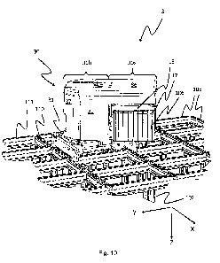
Fig. 10 shows the container handling vehicle 3 where the rotational part 30
has been
rotated approximately 450 in the horizontal plane (P) relative to the X
direction.
Further, Fig. 11 shows the container handling vehicle 3 having the cantilever
30b
directed along the positive X-direction and where the lifting device 16 has
been lowered
10 into the underlying framework 100, towards the topmost storage container
106 of a stack
107.
Fig. 12 shows a second embodiment of the invention where the rotational part
30 of
the vehicle 3 comprises a bulk section 30b and two protruding sections 30a
extending horizontally from the uppermost part of the bulk section 30b. With
the
15 exception of having protruding sections 30a in both positive and
negative X
directions, the configuration of the vehicle 3 in the second embodiment is
identical
or near identical to the first embodiment, that is, with a storage container
lifting
device 16 arranged beneath the lower face of each protruding sections 30a,
where
each lifting device 16 comprises one or more lifting shafts 15 connected to
one or
20 more lifting motors 15a, one or more lifting belts 14 and a lifting
plate 13, and
where the lifting plate 13 further comprises one or more engagement devices 12
and
one or more guiding pins 17. As is most apparent in Fig. 12 (b) and (c), the
vehicle
3 of the second embodiment has a footprint in the X direction covering three
grid
openings 15 and a footprint in the Y direction covering a single grid opening.
As for
the first embodiment, the vehicle battery 40 may either be fixed within the
bulk
section 30b or replaceable as exemplified in the patent publication WO
2015/104263 incorporated herein by reference.
In addition to the advantage concerning arrangement of ports and access to
storage
cells at storage grid boundaries, the vehicle 3 of the second embodiment also
have
the advantage of allowing simultaneous or sequential handling of a plurality
of
storage containers 106, for example lowering a storage container at one side
of the
vehicle 3 while raising another storage container at the opposite side of the
vehicle
3. Or lowering / raising two storage containers simultaneously. Or
lowering/raising
two storage containers from/to the same storage column by rotating the
rotational
part 180 .
In both the first and second embodiment of the invention, the base 31 of the
vehicle
3 is arranged fully within both the vertical and horizontal extent of the
wheel
arrangement 18. Further, the vehicle battery 40 is arranged within, onto or
under the
AMENDED SHEET
PCT/EP 2018/081 892 - 17.12.2019
CA 03082634 2020-05-14
21
bulk section 30b of the rotational part 30. Figs. 13-14 shows a third
embodiment of
the invention where the base 31 extends above, or is arranged above, the wheel
arrangement 18. In this particular embodiment, at least some bulky components
such as the vehicle battery 40 may advantageously be arranged onto or within
the
base 31 instead of the rotational part 30. In Figs. 13-14, a battery receiving
structure
40a is shown on the vertical wall 37 of the vehicle's base 31 facing the
negative X
direction. When the vehicle battery 40 is to be replaced, the vehicle 3 moves
to a
dedicated charging station (not shown) and perform the battery exchange
similar or
equal to the battery exchange disclosed in WO 2015/104263 incorporated herein
by
reference. In order to avoid or reduce interference with the cantilever 30a,
the
rotational part 30 may optionally rotate 90 relative to the base 31 prior to
battery
exchange with the charging station. Alternatively, the vehicle battery 40 may
be
mounted on the side walls.
As schematically illustrated in Fig. 16, a single storage container lifting
device 16
may also handle a plurality of storage containers 106 may equipping the
lifting
device 16 with a number of engagement devices 12 such as claws or clips that
corresponds to the total number of upper horizontal corner of the storage
containers
106 to be picked by the vehicle 3 in the same picking operation. Fig. 16 shows
a
specific example of 4x4 clips allowing up to four storage containers 106 to be
picked in the same operation, assuming a 2x2 storage container configuration
within
a storage column. Each, some or all the clips in each lifting unit 6 may be
remotely
operated by a control system. As explained above, each corner of the lower
face of
the lifting plate 13 is preferably arranged with one or more guiding pins 17
to
ensure adequate guiding of the engagement devices 12 on or into corresponding
engagement device receiving structures.
In the preceding description, various aspects of an automated storage and
retrieval
system, a vehicle and a method according to the invention have been described
with
reference to the illustrative embodiment. However, this description is not
intended
to be construed in a limiting sense. Various modifications and variations of
the
illustrative embodiment, as well as other embodiments of the system, the
vehicle
and the method which are apparent to persons skilled in the art, are deemed to
lie
within the scope of the present invention as defined by the following claims.
As an
example, an automated storage and retrieval system may be envisaged where the
above mentioned inventive cantilever vehicles operates in conjunction with
prior art
vehicles such as the central cavity vehicles disclosed in W02014/090684A1, the
single cell vehicles disclosed in W02015/193278A1 and/or the non-rotational
cantilever vehicles disclosed in NO317366, and where the cantilever of each
AMENDED SHEET
PCT/EP 2018/081 892 - 17.12.2019
CA 03082634 2020-05-14
22
inventive cantilever vehicles is high enough above the rail system to allow
one or
more of the prior art vehicles to drive under during operation.
AMENDED SHEET