Note: Descriptions are shown in the official language in which they were submitted.
WELDER FOR LAMINATES WITH DISSIMILAR WELDING SURFACES
FIELD
[0001] This application claims priority to and all benefit of U.S. Provisional
Application No.
62/950,979, filed on December 20, 2019, the entire disclosure of which is
fully incorporated
herein by reference.
[0002] The general inventive concepts relate to geomembranes and to an
improved device for
welding discrete pieces of the geomembrane material together.
BACKGROUND
[0003] As known in the art, geomembranes are low permeability synthetic
membrane liners or
barriers that are used to control fluid migration. Typical uses for
geomembranes include heavy-
duty covers and temporary liners for various applications in oil fields,
landfills, water
containments, remediation, agriculture, etc. Geomembranes are often made from
relatively thin
continuous polymeric sheets.
[0004] A conventional geomembrane 100 is shown in FIGS. 1A-1B. The geomembrane
100
includes a first side 102, a second side 104, a third side 106, and a fourth
side 108. The distance
between the first side 102 and the second side 104 defines the length / of the
geomembrane 100.
The distance between the third side 106 and the fourth side 108 defines the
width w of the
geomembrane 100. Typically, during production the width w of the geomembrane
100 is
constrained by processing and packaging concerns, while the length / of the
geomembrane 100
can be as long as desired. Consequently, the width w is often considerably
less than the length /.
Often, the geomembrane 100, once produced, is stored on a roll.
[0005] The geomembrane 100 also includes a fifth side 110 and a sixth side
112. The fifth side
110 defines an upper surface Su and the sixth side 112 defines a lower surface
Si of the
geomembrane 100. The distance between the fifth side 110 and the sixth side
112 defines the
thickness t of the geomembrane 100.
1
Date Recue/Date Received 2020-06-10
[0006] Geomembranes typically include multiple distinct polymeric layers. The
layers are
joined to one another (e.g., coated together, adhered together) to form the
geomembrane. For
example, the geomembrane 100 includes four distinct layers including a first
layer 120, a second
layer 122, a third layer 124, and a fourth layer 126. The first layer 120
defines the upper surface
Su of the geomembrane 100, while the fourth layer 126 defines the lower
surface Si of the
geomembrane 100. In the geomembrane 100, while the second layer 122 and the
third layer 124
are different from the first layer 120, the fourth layer 126 is the same as
the first layer 120.
[0007] As noted above, because the width w of the geomembrane 100 is rarely
wide enough for
a particular application, a first instance 130 of the geomembrane 100 is
positioned next to a
second instance 140 of the geomembrane 100, such that a portion of the
geomembranes 130, 140
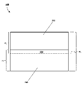
overlap with one another to form an overlapped region 150. The first
geomembrane 130 has a
first width w/ and the second geomembrane 140 has a second width w2, wherein
w/ typically
equals w2. The overlapped region 150 has a third width w3 and defines an area
where the
geomembranes 130, 140 are joined together, such as by thermal bonding (i.e.,
welding). The
joined geomembranes 130, 140 form a geomembrane 200 having a fourth width w4
(i.e., (wi +
w2) - w3). The process can be repeated with additional lengths of geomembranes
to achieve a
desired overall width.
[0008] FIGS. 3A-3C illustrate a wedge welder 300 for welding two overlapped
sheets of
geomembrane material, such as the geomembranes 130, 140 shown in FIG. 2. The
wedge
welder 300 is typically a hand-held device that is positioned to traverse an
overlapped region
(e.g., the overlapped region 150) in a direction indicated by arrow 380.
[0009] The wedge welder 300 includes a body 302, a wedge 304, a guide plate
306, and a
pressure mechanism (here, a pair of rollers 308). The body 302 holds the other
components
together and can include additional structure, such as a handle (not shown).
[0010] The wedge 304 includes a heating element 310, as shown in FIG. 3C, that
relatively
evenly heats an upper surface 312 of the wedge 304 and a lower surface 314 of
the wedge 304.
In this manner, the upper surface 312 of the wedge 304 defines a first heating
path 320 between
2
Date Recue/Date Received 2020-06-10
points 322 and 324, while the lower surface 314 of the wedge 304 defines a
second heating path
326 between points 328 and 330.
[0011] The guide plate 306 includes a body 340 that extends between a first
end 342 and a
second end 344. The body 304 is often made of metal (e.g., stainless steel).
The first end 342 of
the body 340 is separated from the wedge 304 by a fixed distance that forms a
gap g.
[0012] As shown in FIG. 3B, the guide plate 306 guides the overlapped sheets
so that an upper
sheet of the geomembrane material (i.e., the geomembrane 130) is conveyed to
the upper surface
312 of the wedge 304 and a lower sheet of the geomembrane material (i.e., the
geomembrane
140) is conveyed to the lower surface 314 of the wedge. After the geomembrane
130 traverses
the first heating path 320 and the geomembrane 140 traverses the second
heating path 326, the
rollers 308 immediately press the heated materials together to form a weld 350
(i.e., a seam of
the geomembrane 200).
[0013] For purposes of illustration, the first heating path 320 and the second
heating path 326
are represented as linear distances in the diagram 400 of FIG. 4. The first
heating path 320 has a
length li and the second heating path 326 has a length 12. Thus, since the
length li is equal to the
length /2 and since the temperature applied along the first heating path 320
is substantially equal
to the temperature applied along the second heating path 326, the lower
surface Si of the
geomembrane 130 and the upper surface Su of the geomembrane 140 forming the
seam 350
receive substantially the same amount of heat applied by the wedge 304. While
this even
application of heat may suffice when the material of the lower surface Si of
the geomembrane
130 and the material of the upper surface Su of the geomembrane 140 are the
same material, it
presents drawbacks when the surfaces being welded are formed of different
materials.
[0014] In view of the above, there is an unmet need for an improved wedge
welder for
thermally bonding geomembranes when the surfaces being welded are dissimilar.
SUMMARY
[0015] The general inventive concepts relate to a welder for joining two
geomembranes
together, wherein the surfaces of the geomembranes being welded together are
dissimilar.
3
Date Recue/Date Received 2020-06-10
Additionally, the general inventive concepts encompass an improved wedge
welder, wherein the
heating profile on one side of the wedge can be varied relative to the heating
profile on the other
side of the wedge, notwithstanding that a single/common heating element is
used.
[0016] In one exemplary embodiment, a welder for joining a first polymeric
sheet and a second
polymeric sheet together by thermal bonding is disclosed. The welder
comprises: a heating
element having a first face defining a first heating length and a second face
defining a second
heating length; and a guide plate for conveying the first polymeric sheet to
the first face and the
second polymeric sheet to the second face, wherein the first heating length is
equal to the second
heating length, and wherein a portion of the guide plate covers a portion of
the first face.
[0017] In some exemplary embodiments, the first polymeric sheet has a lower
surface formed
of a first material, the second polymeric sheet has an upper surface formed of
a second material,
and the first material and the second material are different.
[0018] In some exemplary embodiments, the first polymeric sheet and the second
polymeric
sheet have the same construction.
[0019] In some exemplary embodiments, the first polymeric sheet and the second
polymeric
sheet are geomembranes.
[0020] In some exemplary embodiments, the first polymeric sheet comprises a
plurality of
layers, and the second polymeric sheet comprises a plurality of layers.
[0021] In some exemplary embodiments, the first polymeric sheet comprises four
layers, and
the second polymeric sheet comprises four layers.
[0022] In some exemplary embodiments, the heating element is a wedge-shaped
member, such
that a distance between the first face of the heating element and the second
face of the heating
element varies over a length of the heating element.
4
Date Recue/Date Received 2020-06-10
[0023] In some exemplary embodiments, the welder is portable and includes a
handle for
carrying the welder.
[0024] In some exemplary embodiments, the heating element heats the upper face
and the
lower face to a welding temperature, wherein the welding temperature is in the
range of 315 C
to 460 C.
[0025] In some exemplary embodiments, the heating element heats the upper face
and the
lower face to a welding temperature, wherein the welding temperature is in the
range of 350 C
to 400 C.
[0026] In some exemplary embodiments, the guide plate is metal.
[0027] In some exemplary embodiments, the guide plate is stainless steel.
[0028] In some exemplary embodiments, a width of the guide plate is in the
range of 3.0 inches
to 3.5 inches.
[0029] In some exemplary embodiments, a length of the guide plate is in the
range of 5.0
inches to 6.0 inches.
[0030] In some exemplary embodiments, a length of the guide plate is in the
range of 6.5
inches to 7.5 inches.
[0031] In some exemplary embodiments, a thickness of the guide plate is in the
range of 0.5
inches to 0.7 inches.
[0032] In some exemplary embodiments, the guide plate is fixed relative to the
heating
element.
[0033] In some exemplary embodiments, the guide plate is adjustable relative
to the heating
element.
Date Recue/Date Received 2020-06-10
[0034] In some exemplary embodiments, the guide plate is manually adjustable
relative to the
heating element.
[0035] In some exemplary embodiments, the guide plate is motorized for
automatic
adjustment.
[0036] In some exemplary embodiments, the portion of the guide plate covers
between 5% to
95% of the first face of the heating element.
[0037] In some exemplary embodiments, the portion of the guide plate covers
between 15% to
85% of the first face of the heating element.
[0038] In some exemplary embodiments, the portion of the guide plate covers
between 25% to
75% of the first face of the heating element.
[0039] In some exemplary embodiments, the portion of the guide plate covers
between 35% to
65% of the first face of the heating element.
[0040] In some exemplary embodiments, the portion of the guide plate covers
between 45% to
55% of the first face of the heating element.
[0041] In some exemplary embodiments, the portion of the guide plate covers at
least one third
of the first face of the heating element.
[0042] In some exemplary embodiments, the portion of the guide plate covers at
least one half
of the first face of the heating element.
[0043] In some exemplary embodiments, the portion of the guide plate covers
half of the first
face of the heating element.
[0044] In one exemplary embodiment, a method of joining a first polymeric
sheet and a second
polymeric sheet together by thermal bonding is disclosed. The method
comprises: providing a
wedge-shaped heating element having a first face defining a first heating
length extending from a
6
Date Recue/Date Received 2020-06-10
first point to a second point and a second face defining a second heating
length extending from a
third point to a fourth point; conveying the first polymeric sheet to the
first face of the heating
element so that the first polymeric sheet travels less than the first heating
length; and conveying
the second polymeric sheet to the second face of the heating element so that
the second
polymeric sheet travels the second heating length.
[0045] Other aspects and features of the general inventive concepts will
become more readily
apparent to those of ordinary skill in the art upon review of the following
description of various
exemplary embodiments in conjunction with the accompanying figures.
BRIEF DESCRIPTION OF THE DRAWINGS
[0046] The general inventive concepts, as well as embodiments and advantages
thereof, are
described below in greater detail, by way of example, with reference to the
drawings in which:
[0047] FIGS. 1A-1B are diagrams illustrating a conventional multi-layer
geomembrane,
wherein the upper layer and the lower layer are the same.
[0048] FIG. 2 is a diagram illustrating two pieces of the geomembrane of FIGS.
1A-1B
positioned relative to one another in advance of welding the pieces together.
[0049] FIGS. 3A-3C are diagrams illustrating (a side view of) a conventional
welding device
for welding the geomembrane pieces of FIG. 2 together.
[0050] FIG. 4 is a diagram illustrating the heating paths that each of the
geomembrane pieces
of FIG. 2 travels during the welding process.
[0051] FIGS. 5A-5B are diagrams illustrating a multi-layer geomembrane,
wherein the upper
layer and the lower layer are dissimilar.
[0052] FIG. 6 is a diagram illustrating two pieces of the geomembrane of FIGS.
5A-5B
positioned relative to one another in advance of welding the pieces together.
7
Date Recue/Date Received 2020-06-10
[0053] FIGS. 7A-7C are diagrams illustrating (a side view of) a welding
device, according to
one exemplary embodiment, for welding the geomembrane pieces of FIG. 6
together.
[0054] FIG. 8 is a diagram illustrating the heating paths that each of the
geomembrane pieces
of FIG. 6 travels during the welding process.
[0055] FIG. 9 is a graph showing comparative data from welding geomembrane
materials
having dissimilar surfaces together with a conventional welder and a modified
welder.
DETAILED DESCRIPTION
[0056] Several illustrative embodiments will be described in detail with the
understanding that
the present disclosure merely exemplifies the general inventive concepts.
Embodiments
encompassing the general inventive concepts may take various forms and the
general inventive
concepts are not intended to be limited to the specific embodiments described
herein.
[0057] The general inventive concepts relate to a welder for joining two
geomembranes
together, wherein the surfaces of the geomembranes being welded together are
dissimilar. In
some exemplary embodiments, the welder is a wedge welder, wherein the heating
profile on one
side of the wedge can be varied relative to the heating profile on the other
side of the wedge,
notwithstanding that a single/common heating element is used.
[0058] A geomembrane 500 is shown in FIGS. 5A-5B. The geomembrane 500 includes
a first
side 502, a second side 504, a third side 506, and a fourth side 508. The
distance between the
first side 502 and the second side 504 defines the length / of the geomembrane
500. The distance
between the third side 506 and the fourth side 508 defines the width w of the
geomembrane 500.
Typically, during production the width w of the geomembrane 500 is constrained
by processing
and packaging concerns, while the length / of the geomembrane 500 can be as
long as desired.
Consequently, the width w is often considerably less than the length /. Often,
the geomembrane
500, once produced, is stored on a roll.
8
Date Recue/Date Received 2020-06-10
[0059] The geomembrane 500 also includes a fifth side 510 and a sixth side
512. The fifth side
510 defines an upper surface Su and the sixth side 512 defines a lower surface
Si of the
geomembrane 500. The distance between the fifth side 510 and the sixth side
512 defines the
thickness t of the geomembrane 500.
[0060] In some exemplary embodiments, the geomembrane 500 has a width w in the
range of
140 inches to 150 inches. In some exemplary embodiments, the geomembrane 500
has a length /
in the range of 1,000 feet to 1,800 feet. In some exemplary embodiments, the
geomembrane 500
has a thickness tin the range of 0.02 inches to 0.05 inches.
[0061] The geomembrane 500 includes one or more polymeric layers. Typically,
the
geomembrane 500 includes at least two distinct polymeric layers. In this case,
the layers are
joined to one another (e.g., coated together, adhered together) to form the
geomembrane. For
example, the geomembrane 500 includes four distinct layers including a first
layer 520, a second
layer 522, a third layer 524, and a fourth layer 526. The first layer 520
defines the upper surface
Su of the geomembrane 500. The fourth layer 526 defines the lower surface Si
of the
geomembrane 500.
[0062] In the geomembrane 500, the first layer 520 and the fourth layer 526
are different from
one another (e.g., made from different materials or otherwise have
significantly different melting
temperatures). The second layer 522 and the third layer 524 may be the same or
different.
Additionally, each of the second layer 522 and the third layer 524 may be the
same as or
different from the first layer 520 and/or the fourth layer 526. It should be
noted that the general
inventive concepts are not limited to any particular geomembrane construction,
as long as the
two materials being heated for welding together are dissimilar. Thus, the
geomembrane may
have any number of layers.
[0063] Geomembranes are synthetic membrane liners or barriers used to control
fluid
migration in a manmade project, structure, or system. They are made from
relatively thin
continuous polymeric sheets that are sometimes made from the infusion of
geotextiles with
asphalt, elastomer, or polymer sprays.
9
Date Recue/Date Received 2020-06-10
[0064]
Geomembranes often have a range of chemical resistance and physical properties
that
make them suitable for a diverse range of applications including, but not
limited to, use as liners
in oil fields, landfills, water containments, wastewater remediations, and the
agriculture industry.
[0065] However, because the width w of the geomembrane 500 is rarely wide
enough for a
particular application, a first instance 530 of the geomembrane 500 is
positioned next to a second
instance 540 of the geomembrane 500, such that a portion of the geomembranes
530, 540
overlap with one another to form an overlapped region 550. The first
geomembrane 530 has a
first width w/ and the second geomembrane 540 has a second width w2, wherein
w/ typically
equals w2. The overlapped region 550 has a third width w3 and defines an area
where the
geomembranes 530, 540 are joined together, such as by thermal bonding (i.e.,
welding). In some
exemplary embodiments, the width w3 of the overlapped region 550 (i.e., the
eventual weld
seam) is in the range of 3 inches to 5 inches. The joined geomembranes 530,
540 form a
geomembrane 600 having a fourth width w4 (i.e., (wi + w2) - w3). The process
can be repeated
with additional lengths of geomembrane to achieve a desired overall width.
Thus, the overall
dimensions of the geomembrane 600 are customizable. In some instances, the
geomembrane
600 can be made to cover a relatively large area in the range of 100,000
square feet to 200,000
square feet.
[0066] FIGS. 7A-7C illustrate an improved wedge welder 700, according to one
exemplary
embodiment, for welding two overlapped sheets of geomembrane material, such as
the
geomembranes 530, 540 shown in FIG. 6. The wedge welder 700 is typically a
hand-held device
that is positioned to traverse an overlapped region (e.g., the overlapped
region 550) in a direction
indicated by arrow 780. In other words, the welder 700 moves in the direction
780, while the
geomembranes 530, 540 retain their position. In some exemplary embodiments,
the welder 700
can achieve a maximum welding speed in the range of 8 ft./min (fpm) to 32
ft./min. (fpm),
depending on the material being welded.
[0067] The wedge welder 700 includes a body 702, a wedge 704, a guide plate
706, and a
pressure mechanism (here, a pair of rollers 708). The body 702 holds the other
components
together and can include additional structure, such as a handle (not shown).
In some exemplary
Date Recue/Date Received 2020-06-10
embodiments, the welder 700 has a compact design and relatively light weight
that renders it
particularly suited for joining sheets of geomembrane material together in the
field. The guide
plate 706 typically supports high speed in-house fabrication.
[0068] The wedge 704 includes a heating element 710, as shown in FIG. 7C, that
relatively
evenly heats an upper surface 712 of the wedge 704 and a lower surface 714 of
the wedge 704.
The heating element 710 can be a single heating element or multiple heating
elements disposed
along a length of the wedge 704. In this manner, the upper surface 712 of the
wedge 704 defines
a first heating path 720 between points 722 and 724, while the lower surface
714 of the wedge
704 defines a second heating path 726 between points 728 and 730. In some
exemplary
embodiments, the heating element 710 can achieve temperatures in the range of
315 C to 460
C. In some exemplary embodiments, the geomembrane materials are thermally
bonded together
at temperatures in the range of 350 C to 400 C.
[0069] The guide plate 706 includes a body 740 that extends between a first
end 742 and a
second end 744. In some exemplary embodiments, the body 704 is made of metal.
In some
exemplary embodiments, the body 704 is made of stainless steel. As it is the
positioning of the
guide plate 706 relative to the wedge 704 that is important, the guide plate
706 can have any
suitable dimensions (width, length, thickness). Of note, the guide plate 706
is positioned to
overlap or otherwise cover a portion of the upper surface 712 of the wedge
704.
[0070] In some exemplary embodiments, a width of the guide plate 706 is in the
range of 3.0
inches to 3.5 inches. In some exemplary embodiments, a length of the guide
plate 706 is in the
range of 5.0 inches to 6.0 inches. In some exemplary embodiments, a length of
the guide plate
706 is in the range of 6.5 inches to 7.5 inches. In some exemplary
embodiments, a thickness of
the guide plate 706 is in the range of 0.5 inches to 0.7 inches.
[0071] As shown in FIG. 7B, the guide plate 706 guides the overlapped sheets
so that an upper
sheet of the geomembrane material (i.e., the geomembrane 530) is conveyed to
the upper surface
712 of the wedge 704 and a lower sheet of the geomembrane material (i.e., the
geomembrane
540) is conveyed to the lower surface 714 of the wedge. After the geomembrane
530 traverses
the first heating path 720 and the geomembrane 540 traverses the second
heating path 726, the
11
Date Recue/Date Received 2020-06-10
rollers 708 immediately press the heated materials together to form a weld 750
(i.e., a seam of
the geomembrane 600).
[0072] For purposes of illustration, the first heating path 720 and the second
heating path 726
are represented as linear distances in the diagram 800 of FIG. 8. The first
heating path 720 has
an actual length //, and the second heating path 726 has an actual length 12,.
Since the length ha
is equal to the length 12, and since the temperature applied along the first
heating path 720 is
substantially equal to the temperature applied along the second heating path
726, the lower
surface Si of the geomembrane 530 and the upper surface Su of the geomembrane
540 forming
the seam 750 would normally receive substantially the same amount of heat
applied by the
wedge 704.
[0073] However, since the lower surface Si of the geomembrane 530 and the
upper surface Su
of the geomembrane 540 are formed from different materials, this even heating
of the surfaces Si,
Su results in a seam that would have decreased properties (e.g., peel
strength, shear strength).
Thus, in the case of the welder 700, the guide plate 706 is positioned to
overlap or otherwise
cover a portion of the upper surface 712 of the wedge 704, as noted above.
[0074] More specifically, as shown in FIG. 7C, the first end 742 of the body
740 of the guide
plate 706 is positioned between the points 722 and 724 of the upper surface
712 of the wedge
704. In this manner, a portion (e.g., > 10%) of the upper surface 712 of the
wedge 704 is
prevented from contacting the lower surface Si of the geomembrane 530, which
results in a
different heating profile being applied to the lower surface Si of the
geomembrane 530 than to
the upper surface Su of the geomembrane 540, by the wedge 704.
[0075] In other words, positioning of the guide plate 706 on the upper surface
712 of the
wedge 704 results in the first heating path 720 having a reduced length (i.e.,
an effective length
Lie) as compared to the actual length /is. The difference between the actual
length hi a and the
effective length be is equal to the distance between the first end 742 of the
body 740 of the guide
plate 706 and the point 724 on the wedge 704.
12
Date Recue/Date Received 2020-06-10
[0076] Consequently, as shown in FIG. 8, the first heating path 720 has a
length lie that is
significantly (i.e., > 5%) smaller than the length /2, of the second heating
path 726. As a result,
the lower surface Si of the geomembrane 530 and the upper surface Su of the
geomembrane 540
forming the seam 750 do not receive the same amount of heat applied by the
wedge 704, such
that the resulting weld (i.e., the seam 750) can exhibit improved properties
(e.g., peel strength,
shear strength).
[0077] In some exemplary embodiments, the position of the guide plate 706 on
the upper
surface 712 of the wedge 704 is fixed. This may be advantageous, for example,
when the welder
700 will be processing the same type of geomembrane material over and over
again.
[0078] In some exemplary embodiments, the position of the guide plate 706 on
the upper
surface 712 of the wedge 704 is variable or otherwise adjustable. This may be
advantageous, for
example, when the welder 700 will be processing many different types of
geomembrane
materials, at least some of which have dissimilar upper and lower surfaces.
[0079] In some exemplary embodiments, the position of the guide plate 706 on
the upper
surface 712 of the wedge 704 can be adjusted so that the effective length lie
of the first heating
path 720 is in the range of 5% to 95% of the actual length //a. In some
exemplary embodiments,
the position of the guide plate 706 on the upper surface 712 of the wedge 704
can be adjusted so
that the effective length lie of the first heating path 720 is in the range of
15% to 85% of the
actual length //a. In some exemplary embodiments, the position of the guide
plate 706 on the
upper surface 712 of the wedge 704 can be adjusted so that the effective
length lie of the first
heating path 720 is in the range of 25% to 75% of the actual length //a. In
some exemplary
embodiments, the position of the guide plate 706 on the upper surface 712 of
the wedge 704 can
be adjusted so that the effective length lie of the first heating path 720 is
in the range of 35% to
65% of the actual length //a. In some exemplary embodiments, the position of
the guide plate
706 on the upper surface 712 of the wedge 704 can be adjusted so that the
effective length lie of
the first heating path 720 is in the range of 45% to 55% of the actual length
//a.
[0080] While the illustrated embodiments disclose covering at least a portion
of the upper
surface 712 of the wedge 704 of the welder 700 with the guide plate 706 to
alter the first heating
13
Date Recue/Date Received 2020-06-10
path 720, it should be appreciated that the general inventive concepts also
encompass
(alternatively or additionally) covering at least a portion of the lower
surface 714 of the wedge
704 of the welder 700 with the guide plate 706 to alter the second heating
path 726.
[0081] As noted above, the ability of the welder 700 to vary the heating
profile presented by
the first heating path 720 relative to the second heating path 726 allows the
welder 700 to
produce welds (e.g., the seam 750) with improved properties (e.g., peel
strength, shear strength).
[0082] To illustrate such improvements, a welder was used to weld discrete
pieces of a
geomembrane material together. Here, the welder was a Pro-Wedge Model VM-20
wedge
welder sold by DemTech Services of Diamond Springs, California; and the
geomembrane
material was the RhinoMatO 750 reinforced composite geomembrane product sold
by Owens
Corning of Toledo, Ohio.
[0083] The RhinoMatO 750 geomembrane product is a 30 mil (0.76 mm) thick,
polyethylene
reinforced composite geomembrane (RCG) specifically designed for use in water
retention and
containment applications. The RhinoMatO 750 geomembrane product has four
distinct layers
(from the top to the bottom): (1) an upper SurFlexTm UV resistant film (140
g/m2); (2) an
LLDPE/LDPE coating (80 g/m2); an HDPE scrim (267.7 g/m2); and a lower
LLDPE/LDPE
coating (100 g/m2). Because the upper layer and the lower layer materials are
different, the
conventional welder 300 is unable to achieve a higher quality weld.
[0084] To show this phenomenon, the Pro-Wedge Model VM-20 wedge welder was
used in its
commercially-available form (similar to the welder 300) to generate standard
data and in a form
modified according to the general inventive concepts (similar to the welder
700) to generate
modified data. The standard data and the modified data are plotted in the
graph 900 of FIG. 9.
The welds produced on the RhinoMatO 750 geomembrane product using the modified
welder
exhibited superior performance versus the welds produced on the RhinoMatO 750
geomembrane
product using the conventional (i.e., unmodified) welder. For example, the
welds produced on
the RhinoMatO 750 geomembrane product using the modified welder had up to 37%
increased
peel strength (lbs./ft.). As another example, the welds produced on the
RhinoMatO 750
14
Date Recue/Date Received 2020-06-10
geomembrane product using the modified welder had up to 27% increased shear
strength
(lbs./ft.).
[0085] The scope of the general inventive concepts presented herein are not
intended to be
limited to the particular exemplary embodiments shown and described herein.
From the
disclosure given, those skilled in the art will not only understand the
general inventive concepts
and their attendant advantages, but will also find apparent various changes
and modifications to
the devices and systems disclosed. For example, while the exemplary
embodiments described
and shown herein relate to a geomembrane material, the general inventive
concepts may
encompass other polymeric materials that are welded together (e.g.,
geotextiles). As another
example, while the exemplary embodiments described and shown herein use
existing structure of
the welder (e.g., a guide plate) to overlap or otherwise cover a portion of a
surface of the heated
wedge, the general inventive concepts encompass the use of other structure
(including structure
not native to the welder) for such purpose. It is sought, therefore, to cover
all such changes and
modifications as fall within the spirit and scope of the general inventive
concepts, as described
and/or claimed herein, and any equivalents thereof.
Date Recue/Date Received 2020-06-10