Note: Descriptions are shown in the official language in which they were submitted.
CA 03083449 2020-05-25
WO 2019/108224 PCT/US2017/064178
EXTRA JOINT STABILIZATION CONSTRUCT
Background
[0001] Ligaments interconnect bones of the skeletal system and are involved
with the stabilization and kinematics of skeletal joints. Various injuries may
occur
that result in compromised ligament function and/or bone fractures. Such
injuries
include, for example, partial and complete tears and avulsion of the bone
where a
ligament attaches to a bone. Such injuries occur throughout the skeletal
system.
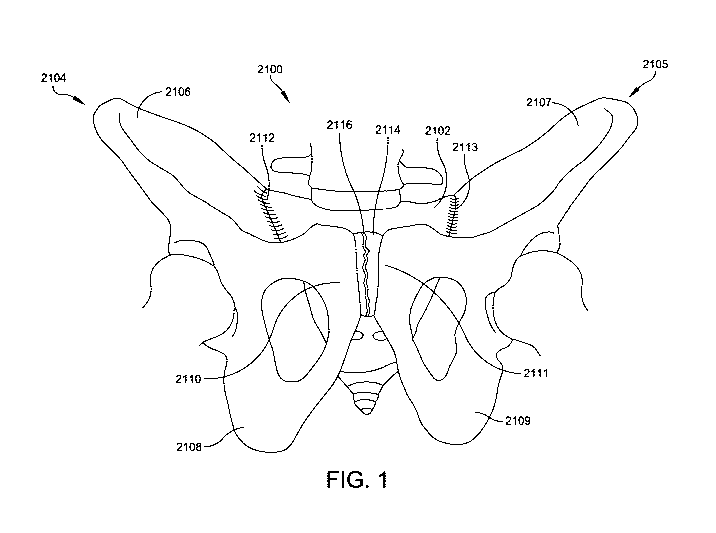
[0002] By way of example, the human pelvis 2100 is a complex junction of
multiple bones and soft tissues, as shown in FIG. 1. The sacrum 2102 bounds
the
posterior aspect of the pelvis with a pair of hip bones 2104, 2105 bounding
the
lateral and anterior aspects of the pelvis. Each hip bone is composed of three
parts including the ilium 2106, 2107; ischium 2108, 2109; and pubis 2110,
2111.
The sacrum is joined to each hip bone 2104, 2105 by strong ligaments at the
sacroiliac joint 2112, 2113. The hip bones 2104, 2105 are joined anteriorly at
the
cartilaginous pubic symphysis 2114.
[0003] Various conditions may cause the pelvis to become unstable. For
example, childbirth and traumatic injury may result in instability at the
sacroiliac
joint 2112, 2113 and/or the pubic symphysis 2114. For example, a traumatic
anterior-posterior compression fracture may result in a separation 2116
between
the hip bones at the pubic symphysis 2114, as shown in FIG. 1, and loosening
of
the sacroiliac joint 2112, 2113 leading to pelvic instability.
[0004] In another example, the human ankle 100 is a complex junction of
multiple bones and soft tissues, as shown in FIGS. 2-4. The ankle includes
joints
between the tibia 102, fibula 104, and talus 106. The joint between the tibia
102
and fibula 104 is a syndesmosis or slightly movable joint in which the bones
are
joined together by connective tissue. The syndesmosis between the tibia and
fibula includes the anterior inferior tibiofibular ligament (AITFL) 110, the
posterior
inferior tibiofibular ligament (PITFL) 112, and the interosseous ligament
(I0L) 114
(FIG. 4). The syndesmosis ligaments are often injured in high ankle sprains.
Other injury prone ligaments of the ankle joint include, among others, the
anterior
talofibular ligament (ATFL) 120, the posterior talofibular ligament (PTFL) 122
and
the deltoid ligament complex 124 including superficial and deep deltoid
ligaments.
CA 03083449 2020-05-25
WO 2019/108224
PCT/US2017/064178
-2-
[0005] What is needed is improved implants, instruments and methods to
stabilize bone fractures and/or reinforce ligaments.
CA 03083449 2020-05-25
WO 2019/108224 PCT/US2017/064178
-3-
Summary
[0007] This Summary is provided to introduce a selection of concepts in a
simplified form that are further described below in the Detailed Description.
This
Summary is not intended to identify key aspects or essential aspects of the
claimed subject matter. Moreover, this Summary is not intended for use as an
aid
in determining the scope of the claimed subject matter.
[0008] One embodiment provides a knotless returning and locking system for
bone fracture stabilization and soft tissue repair and reinforcement. The
system
comprises a returning and locking anchor having a body with a proximal end, a
distal end, and defining a longitudinal axis, the body forming an internal
passage
and a return feature, the internal passage having a threaded receiver located
at the
proximal end of the body and including a proximal portion, a mid portion, and
a
distal portion, the return feature located distal to the threaded receiver and
in
communication with the internal passage. The system also includes a threaded
set
screw having a proximal portion, a mid portion, and a distal portion, the
threaded
set screw configured for rotational insertion into the threaded receiver to
achieve a
progressively increasing interference fit about a flexible synthetic strand
passing
between the proximal portions and the mid portions of the threaded receiver
and
the threaded set screw and a progressively decreasing interference fit about
the
flexible synthetic strand passing between the mid portions and the distal
portions of
the threaded receiver and the threaded set screw. The progressively increasing
interference fit and the progressively decreasing interference fit combine to
provide
a locking feature that reversibly secures the flexible synthetic strand in
relation to
the returning and locking anchor.
[0009] Another embodiment provides a counter-torque driver for rotationally
driving an anchor into bone, the anchor having a proximal end, a distal end,
and a
driver feature, the driver feature comprising two opposing slots formed in the
proximal end of the anchor. The counter-torque driver comprises a longitudinal
body extending from a proximal end to a distal end and defining a longitudinal
axis,
the longitudinal body including an axial through hole extending from the
proximal
end to the distal end along the longitudinal axis. The counter-torque driver
also
CA 03083449 2020-05-25
WO 2019/108224 PCT/US2017/064178
-4-
includes two opposing tabs extending from the distal end of the body, the two
tabs
centered about the longitudinal axis and configured to engage with the two
opposing slots formed in the proximal end of the anchor. When the two opposing
tabs of the driver are engaged with the two opposing slots of the anchor and
the
driver is rotated, the suture anchor is rotationally driven into the bone.
When the
two opposing tabs of the driver are engaged with the two opposing slots of the
anchor and the driver is held stationary, each of the tabs provides a distal
facing
bearing surface to resist torsional forces generated when tensioning a
flexible
synthetic strand via a rotational input to a set screw inserted through the
axial
through hole of the driver into the anchor, thereby countering the torsional
forces to
maintain an original insertion alignment of the anchor within the bone.
[0010] Yet another embodiment provides an external construct for
stabilizing a
joint. The construct comprises a flexible synthetic strand having first and
second
opposing ends, a first fixation secured at the first end of the flexible
synthetic
strand, and a second fixation secured at the second end of the flexible
synthetic
strand. The second fixation comprises a returning and locking anchor inserted
into
a bone portion, where the returning and locking anchor has a body with a
proximal
end, a distal end, and defines a longitudinal axis, and where the body forms
an
internal passage having a threaded receiver located at the proximal end and a
return feature located distal to the threaded receiver and in communication
with the
internal passage, where (1) the second end of the flexible synthetic strand
enters
the returning and locking anchor through the axial passage at the proximal end
of
the body, routes around the return feature, and exits the returning and
locking
anchor through the axial passage at the proximal end of the body; (2) the
flexible
synthetic strand is tensioned between the first and the second fixations; and
(3) the
second end of the flexible synthetic strand is locked relative to the
returning and
locking anchor via a threaded set screw that is rotationally inserted into the
threaded receiver resulting in a continuous, uninterrupted length of the
flexible
synthetic strand extending externally across the joint between the first and
the
second fixations.
[0011] Additional objects, advantages and novel features of the technology
will
CA 03083449 2020-05-25
WO 2019/108224
PCT/US2017/064178
-5-
be set forth in part in the description which follows, and in part will become
more
apparent to those skilled in the art upon examination of the following, or may
be
learned from practice of the technology.
CA 03083449 2020-05-25
WO 2019/108224 PCT/US2017/064178
-6-
Brief Description of the Drawings
[0012] Non-limiting and non-exhaustive embodiments of the present
invention,
including the preferred embodiment, are described with reference to the
following
figures, wherein like reference numerals refer to like parts throughout the
various
views unless otherwise specified. Illustrative embodiments of the invention
are
illustrated in the drawings, in which:
[0013] FIG. 1 illustrates an anterior view of a human pelvis having an
anterior-posterior compression fracture;
[0014] FIGURE 2 illustrates a right view of a human ankle joint;
[0015] FIGURE 3 illustrates a front view of a human ankle joint;
[0016] FIGURE 4 illustrates a rear view of a human ankle joint;
[0017] FIGURES 5-7 illustrate respective top, front, and cross-sectional
views
of one embodiment of a returning and locking anchor;
[0018] FIGURE 8 illustrates a cross-sectional view of a receiver of a
suture
locking feature of the suture returning and locking anchor of FIGURES 5-7;
[0019] FIGURE 9 illustrates a cross-sectional view of the receiver of
FIGURE 8
having a set screw inserted therein to form an interference fit between a
suture and
the receiver and the set screw;
[0020] FIGURE 10 illustrates a front view of the set screw of FIGURE 9
without
threading;
[0021] FIGURE 11 illustrates the cross-sectional view of the set screw and
the
receiver of FIGURE 9, without threading;
[0022] FIGURES 12-14 illustrate respective exploded, front, and
cross-sectional views of another embodiment of a suture returning and locking
anchor;
[0023] FIGURES 15-18 illustrate respective side, perspective-exploded, and
cross-sectional views of one embodiment of an anchor driver engaging with the
returning and locking anchor of FIGURES 5-7;
[0024] FIGURES 19-22 show partial sectional anterior views of the pelvis of
CA 03083449 2020-05-25
WO 2019/108224 PCT/US2017/064178
-7-
FIG. 1 and illustrate the steps of an operative sequence for stabilizing the
compression fracture of FIG. 1 using embodiments of the disclosed devices;
[0025] FIGURE 23 provides a flowchart detailing the operative sequence
illustrated by FIGURES 19-22;
[0026] FIGURE 24 illustrates exemplary reinforcement constructs for the
deltoid
ligament complex and the posterior inferior tibiofibular ligament
(PITFL)/anterior
inferior tibiofibular ligament (AITFL) according to embodiments of the
disclosed
devices;
[0027] FIGURE 25 illustrates one embodiment of a ligament reinforcement
construct using a single suture returning and locking anchor to reinforce two
separate ligaments according to embodiments of the disclosed devices; and
[0028] FIGURE 26 illustrates one embodiment of an attachment construct for
soft tissue repair or tendon reattachment according to embodiments of the
disclosed devices.
CA 03083449 2020-05-25
WO 2019/108224 PCT/US2017/064178
-8-
Detailed Description
[0029] Embodiments are described more fully below in sufficient detail to
enable those skilled in the art to practice the system and method. However,
embodiments may be implemented in many different forms and should not be
construed as being limited to the embodiments set forth herein. The following
detailed description is, therefore, not to be taken in a limiting sense.
[0030] The technology discussed herein relates to apparatus and
corresponding methods of use for preparing ligament reinforcement and bone
fracture repair constructs. Embodiments include a number of suture returning
and
locking anchors, anchor drivers, and extra joint ligament reinforcement and/or
bone fracture repair constructs constructed via operative methods employing
the
devices and instruments described herein.
[0031] Combined Suture Returning and Locking Anchors
[0032] FIGS. 5-7 illustrate top, front, and cross-sectional exploded views
of one
embodiment of a suture returning and locking anchor 400. In FIGS. 5-7, the
anchor 400 includes an anchor body 402 having a proximal end 404, a distal end
406, and defining a longitudinal axis 408. An external bone thread 410 extends
around most of the body 402 except proximally where the thread runs out distal
to
the proximal end, and distally where the thread runs out at a tapered tip 411.
The
bone thread 410 includes a self-tapping flute 412 at the distal end. A set
screw
416 is configured for rotational insertion and locking within the proximal end
404,
as detailed further in relation to FIGS. 8-11 below.
[0033] The anchor 400 includes a suture return feature 413. In more detail
and
in this embodiment, the body 402 includes a first transverse hole 438 forming
opposed openings on opposite sides of the body 402 through which a suture may
be threaded to provide a suture return. While the external bone thread 410 is
engaged in a bone, a flexible synthetic strand such as, for example, a suture,
a
suture tape, a cable or another suitable flexible synthetic strand
(hereinafter a
"flexible strand," "flexible synthetic strand," or "suture") may be pulled
against a
proximal margin 440 of the hole 438 to allow the suture to be tensioned. The
body
further includes an axial hole or passage 441 extending from an opening at the
CA 03083449 2020-05-25
WO 2019/108224 PCT/US2017/064178
-9-
proximal end 404 toward the distal end 406. A second transverse hole 444
extends through the body 402 to form opposed openings on opposite sides of the
body 402. The second transverse hole 444 is offset proximally from the first
transverse hole 438 and communicates with the axial hole 441.
[0034] In use, a suture may be threaded into the axial hole 441 from the
proximal end 404, out one of the openings of the second transverse hole 444,
through the first transverse hole 438, in the other of the openings of the
second
transverse hole 444, and out the axial hole 441 so that the suture is routed
about
the proximal margin 440 within the proximal portion of the body 402.
[0035] The anchor body 402 may further contain relief grooves 446
connecting
the openings of the first and second transverse holes 438, 444 on each side of
the
body 402. The relief grooves 446 allow the suture to pass from the axial hole
441
to the first transverse hole 438 while projecting less, or not at all, from
the sides of
the body 402 to protect the suture from abrasion and to allow the suture to
slide
more easily while it is being routed and tensioned. In this embodiment, the
body
402 provides a tubular extension into a bone to protect the suture from
abrasion
from the bone as well as to protect the bone from abrasion or cutting from the
suture.
[0036] The anchor 400 also includes a suture locking feature detailed in
the
example of FIGS. 8-11. FIG. 8 provides an enlarged view of the internal
features of
a proximal portion 403 of the body 402, and FIG. 9 provides a cross-sectional
view
of the proximal portion 403 of the body 402 in receipt of the set screw 416.
In this
embodiment, the proximal portion 403 of the body 402 includes a receiver 430
having a tapered receiver thread 432, and the set screw 416 has a tapered
external thread 434. Both the receiver thread 432 and the set screw thread 434
are rounded knuckle threads. In addition, the receiver 430/receiver thread 432
and
the set screw 416/set screw thread 434 feature multiple discrete taper angles
that
transition proximally to distally to provide for progressive gripping and
releasing of
the suture 418 to provide a strong grip on the suture while reducing the risk
of
suture damage or severing.
[0037] To address the taper angles in greater detail, FIGS. 10-11
illustrate the
CA 03083449 2020-05-25
WO 2019/108224 PCT/US2017/064178
-10-
set screw 416 and the receiver 430 without their knuckle threading to better
illustrate the gradual transitions of their tapers. In this embodiment, the
set screw
416 is cylindrical at a proximal portion 450, has a relatively small angled
taper over
its mid portion 452, and has a relatively large angled taper over its distal
portion
454 which terminates in a rounded tip 464. The receiver 430 has a relatively
large
angled taper at a proximal portion 456, has a relatively small angled taper
over its
mid portion 458, and is cylindrical at its distal portion 460. When the set
screw 416
and the receiver 430 are mated, they provide progressively less clearance
between them from the proximal end of the anchor 400 to their mid portions and
progressively more clearance between them from their mid portions distally to
the
end of the set screw 416.
[0038] This opposing tapered configuration of the set screw 416 versus the
receiver 430 incorporates the principal of the Morse taper for mating
components.
That is, the opposing conical shapes of the set screw 416 and the receiver 430
are
closely matched in angle at their mid portions 452, 458, causing the
respective
surfaces of the set screw 416 and the receiver 430 to achieve an interference
fit
about the suture 418 over the mid portions 452, 458 of the set screw 416 and
the
receiver 430, with gradual transitions proximally leading into and distally
leading
out of the interference fit. This gradual transition of compression forces
applied to
the suture 418 disposed between the set screw 416 and the receiver 430 leads
to
an enhancement in suture fixation/locking strength, and simultaneously reduces
the risk of severing the suture 418 that is present with greater magnitudes of
compression force transition.
[0039] In one embodiment, the mid portions 452, 458 of the set screw 416
and
the receiver 430 are of the same length and aligned. In this embodiment, there
are
three zones or amounts of clearance between the set screw 416 and the receiver
430 progressing in three steps from a relatively large amount of clearance
proximally to a relatively small amount of clearance over their mid portions
to a
relatively large amount of clearance distally.
[0040] Alternatively, and as shown in the example of FIGS. 8-11, the set
screw
416 can be driven so that the beginning of its mid portion 452 is positioned
distal of
CA 03083449 2020-05-25
WO 2019/108224 PCT/US2017/064178
-11-
the beginning of the receiver mid portion 458, and the end of the set screw
mid
portion 452 is positioned proximal of the end of the receiver mid portion 458,
as
shown in FIG. 11. This arrangement results in five clearance zones 440, 442,
444,
446, and 448 for an even more gradual progression of gripping and releasing of
the
suture 418. Any number of taper angle steps may be provided on the set screw
416 and the receiver 430, and any arrangement of overlap or radius blending
may
be provided to produce any number of progressive clearance steps to transition
proximally to distally from no grip to maximum grip to no grip on the suture
418,
protecting the suture through the gradual increase and decrease of stress
placed
on the suture 418.
[0041] Referring to FIG. 11, the first zone 440 provides the most clearance
proximally and the clearance decreases distally at the angular difference
between
the cylindrical proximal portion 450 of the set screw 416 and the relatively
larger
angle of the proximal portion 456 of the receiver 430. The second zone 442
clearance decreases distally at the angular difference between the cylindrical
proximal portion 450 of the set screw 416 and the relatively smaller angle of
the
mid portion 458 of the receiver 430. The third zone 444 provides the least
clearance and corresponds to where the mid portions 452, 458 of the set screw
416 and the receiver 430 coincide. The fourth zone 446 clearance increases
distally at the angular difference between the relatively smaller angle of the
mid
portion 458 of the receiver 430 and the relatively larger angle of the distal
portion
454 of the set screw 316. The fifth zone 348 provides the most clearance
distally
and the clearance increases distally at the angular difference between the
relatively larger angle of the distal portion 454 of the set screw 316 and the
cylindrical portion 460 of the receiver 330.
[0042] In the illustrative example of FIGS. 8-11, the set screw 416 taper
is
cylindrical in the first proximal portion 450, 10 degrees per side in the
second mid
portion 452, and 20 degrees per side in the distal portion 454. The receiver
430
taper is 40 degrees per side in the first proximal portion 456, 10 degrees per
side in
a second mid portion 458, and cylindrical at a third distal portion 460. The
resulting
relief tapers corresponding to the five zones 440, 442, 444, 446, 448
illustrated in
CA 03083449 2020-05-25
WO 2019/108224 PCT/US2017/064178
-12-
FIG. 11, proximally to distally, are 20 degrees, 10 degrees, 0 degrees, 10
degrees,
and 20 degrees. In this embodiment, the proximal ends 461, 463 of the receiver
430 and the set screw 416 are chamfered and the distal end 464 of the set
screw
416 is rounded to further eliminate any sharp edges to further smooth the path
of
the suture and to provide easier starting of the screw.
[0043] While the embodiment of the suture locking feature of FIGS. 8-11
features opposing tapers on the set screw 416 and the receiver 430, it should
be
understood that the invention contemplates any appropriate tapering
configuration
that provides a gradual increase and decrease of compression forces applied,
proximally to distally, to the interference fit of the suture 418 between the
set screw
416 and the receiver 430. For example, the set screw 416 may be entirely
cylindrical through its proximal, mid, and distal portions, maintaining the
above
described configuration of the receiver 430. In another example, the proximal,
mid,
and distal portions 450, 452, 454 of the set screw 416 may be angled to form
an
egg-like or football shape, while the proximal, mid, and distal portions 456,
458,
460 of the receiver 430 remain cylindrical.
[0044] The locking feature discussed in relation to FIGS. 8-11 provides
both a
knotless and reversible mechanism for locking out the suture 418 relative to
the
returning and locking anchor 400. Because an interference fit between the
suture
418, the set screw 416, and the receiver 430 provides the compression force
required to secure the suture 418 in tension relative to the anchor 400, the
locking
feature provides a knotless fixation, thereby reducing the probability of bone
and/or
tissue abrasion and/or aggravation that is often caused by knotted fixations.
Moreover, because the locking mechanism protects the integrity of the suture
through the gradual increase and decrease of stress placed on the suture 418,
discussed above, the knotless fixation is truly reversible in that the set
screw 416
may be rotationally inserted to lock out the suture 418 relative to the anchor
400
without damaging the suture 418 and/or risking its structural integrity. As a
result, a
surgeon may lock and unlock the suture 418 relative to the anchor 400 multiple
times to achieve an optimal fixation while maintaining confidence in the
quality of
the ultimate knotless fixation.
CA 03083449 2020-05-25
WO 2019/108224 PCT/US2017/064178
-13-
[0045] The body 402 of the suture returning and locking anchor 400 further
includes a driver feature 458 in the form of opposing slots 462 (FIG. 16)
formed in
the proximal wall of the body 402 for receiving an anchor driver such that the
anchor driver does not block the receiver 430 from receiving the set screw 416
and
for providing counter-torque stabilization such that a set screw driver does
not
axially shift the body 402 during insertion of the set screw 416, as discussed
further
below in relation to 15-18.
[0046] FIGS. 12-14 illustrate exploded, front, and cross-sectional views of
another example of a suture returning and locking anchor 500 that is similar
to the
anchor 400. However, the anchor 500 of FIGS. 12-14 is a two-piece anchor
having
an axial through-hole 541 that extends through an entirety of a body 502 of
the
anchor 500.
[0047] In this embodiment, the anchor 500 includes the anchor body 502
having a proximal end 504, a distal end 506, and defining a longitudinal axis
508.
An external bone thread 510 extends around most of the body 502 except
proximally where the thread runs out. The bone thread 510 includes a self-
tapping
flute 512 at the distal end. A set screw 516 is configured for rotational
insertion
and locking according to the locking arrangement discussed above in relation
to
FIGS. 8-11.
[0048] The anchor 500 may provide a suture return function either
internally or
externally. In an internal configuration, the anchor 500 may incorporate a
removable suture return insert 550. The suture return insert 550 includes a
longitudinal body 552 centered about the longitudinal axis 508 and sized to
press
fit within the axial hole 541 extending through the anchor body 502. The
suture
return insert 550 has a proximal end 554, a closed distal end 556, and an
axial hole
or passage 558 extending distally from the proximal end 554. A first
transverse
hole 560 forms opposed openings on opposite sides of the insert body 552. The
first transverse hole 560 communicates with the axial hole 558 of the insert
body
552 such that when the proximal end 554 of the insert 500 is inserted into the
distal
end 506 of the anchor body 502, the first transverse hole 560 within the
insert body
552 aligns with a distal portion of a second transverse hole 538 within the
anchor
CA 03083449 2020-05-25
WO 2019/108224 PCT/US2017/064178
-14-
body 502 to form an internal suture return feature 513, as shown in FIG. 13,
which
is similar to the return feature 413 discussed above in relation to the anchor
400 of
FIGS. 5-7.
[0049] In use in the internal configuration, a suture may be threaded into
the
axial hole 541 of the anchor 500 from the proximal end, out one of the
openings of
the second transverse hole 538 in the anchor body 502, through the first
transverse hole 560 in the insert 550, in the other of the openings of the
second
transverse hole 538, and out the communicating axial holes 441, 558 of the
anchor
body 402 and the insert body 552 such that the suture is routed within the
proximal
portion of the anchor 500. The insert body 552 may further contain relief
grooves
562 connecting the openings of the first and second transverse holes 560, 538
on
each side of the anchor 500, when the insert 550 is disposed within the anchor
body 502. The relief grooves 562 allow the suture to pass from the axial holes
541,
558 to the first transverse hole 560 while projecting less, or not at all,
from the
sides of the anchor body 502 to protect the suture from abrasion and to allow
the
suture to slide more easily while it is being routed and tensioned.
[0050] In an external configuration, the return insert 550 is excluded and
the
suture return is formed by either the second transverse hole 538 or the distal
end
506 of the anchor body 502. In use in the external return configuration, the
suture
enters the axial hole 541 at the proximal end 504 of the anchor 500 and exits
the
axial hole 541 at either the second transverse hole 538 or the distal end of
the
anchor 500, with a return suture path outside the anchor body 502. In various
embodiments, the return suture path passes through a notch or recess formed in
the outer wall of the anchor body, through a relief groove in the bone that
projects
radially from the bone tunnel. Alternatively, the suture may exit the distal
end 506
of the anchor and continue on a path directly to another fixation point (e.g.,
continue along the longitudinal axis 508, without a return, within a bone
tunnel to
another locking anchor).
[0051] Counter-Torque Anchor Driver
[0052] FIGS. 15-18 illustrate an example of an anchor driver 570 for use
with,
for example, the anchor 400 of FIGS. 5-7. The anchor driver includes an
elongated
CA 03083449 2020-05-25
WO 2019/108224 PCT/US2017/064178
-15-
body 572 extending from a proximal end 574 to a distal end 576 and defining a
longitudinal axis 578. The distal end 576 of the driver includes opposed
clearance
slots 580, 582 opening distally and defining spaced apart driver legs 584,
586. The
distal ends of the driver legs 584, 586 form opposing tabs 588 that engage the
opposed slots 462 of the anchor 400. The driver tabs 588 and driver slots 580,
582
are sized so that with the tabs 588 fully engaged in the slots 462 of the
anchor, the
driver slots 580, 582 provide clearance 592, 594 between the driver 570 and
the
anchor 400 for the suture 418.
[0053] A portion of each tab 588 abuts the proximal end of the anchor 400
and
provides a distal facing bearing surface to resist forces (e.g., torsional
forces)
generated when tensioning the suture 418 via a rotational input from a set
screw
driver (not shown) to the set screw 416 to engage the locking mechanism
discussed above in relation to FIGS. 8-11. The anchor driver 570 includes an
axial
through hole 596 to allow passage of the set screw 416 and the set screw
driver
(not shown) for locking the suture 418.
[0054] In use, for example, the anchor 400 is driven into a bone by
engaging
the tabs 588 of the anchor driver 570 with the slots 462 in the anchor, as
shown in
FIG. 18, and rotating the anchor driver 570. A suture 418 is threaded through
the
anchor 400 and passed through the clearance 592, 594 outside of the driver
570, if
the anchor driver 570 has not already been removed. The suture is tensioned
and
then the set screw 416 is driven into the anchor 400 to lock the suture. If
the
anchor driver 570 is still engaged with the anchor 400, the set screw 416 may
be
inserted through the axial through hole 596 in the anchor driver 570. The
torsional
force resistance provided by the anchor driver 570 engagement with the slots
462
ensures that forces applied in locking the suture via the set screw 416 do not
affect
or alter the original insertion alignment of the anchor 400.
[0055] Constructs and Operative Sequences
[0056] FIGS. 19-26 illustrate a number of examples of embodiments of the
disclosed devices in use to stabilize or reinforce ligaments and/or bone
fractures.
In the example of FIGS. 19-22, the exemplary devices and methods are shown in
CA 03083449 2020-05-25
WO 2019/108224 PCT/US2017/064178
-16-
use in a stabilization construct reinforcing the pubic symphysis 2114 to
stabilize the
pelvis 2100 after an anterior-posterior compression fracture 2116.
[0057] Referring to FIGS. 19 and 20, a first anchor 2120 is inserted into
the
pubis 2110 of a first hip bone 2104 from superior to inferior. A flexible
strand 2122
is connected to the first anchor 2120 and extends from the trailing end of the
first
anchor. In the embodiments disclosed herein, the flexible strand may be a
suture,
a suture tape, a cable or another suitable synthetic flexible strand. In the
example
of FIGS. 19-22, the flexible strand 2122 is a braided high strength suture
tape.
[0058] A second anchor 2124 such as, for example, anchors 400 or 500
discussed above in relation to FIGS. 5-13, is inserted into the pubis 2111 of
a
second hip bone 2105 from superior to inferior. The position of the second
anchor
2124 is shown via the broken-out section view of FIG. 20, in which the second
anchor 2124 is shown in cross section. A suture threader or passer 2126
extends
into the proximal or trailing end of the second anchor 2124, around a return
feature
2128, and out the proximal or trailing end of the second anchor 2124. The
flexible
strand 2122 is then threaded through a loop of the passer 2126.
[0059] Referring to FIG. 21, the passer 2126 has been withdrawn from the
proximal end of the second anchor 2124 to pass the end of the flexible strand
2122
into the trailing end or proximal end of the second anchor 2124, around the
return
feature 2128, and out the trailing end of the second anchor 2124. A tension
instrument may then be used to pull the flexible strand 2122 to tension the
portion
of the flexible strand 2122 extending between the anchors 2120 and 2124 and
reduce the pubic symphysis. The flexible strand 2122 may then be locked
relative
to the second anchor 2124 to maintain the reduction in any appropriate manner.
In
this regard, a set screw may be advanced through a central cannulation in the
tension instrument before a set screw driver is advanced through the central
cannulation in the tension instrument and used to thread the set screw into
the
internal threads formed in the second anchor 2124 to lock the flexible strand
2122
relative to the second anchor at the desired tension. The tension instrument
may
then be released and removed. Once the flexible strand is locked, the excess
length of the flexible strand 2122 may be trimmed, as shown in FIG. 22.
CA 03083449 2020-05-25
WO 2019/108224 PCT/US2017/064178
-17-
[0060] A novel repair construct according to examples of the invention has
been shown with anchors inserted into the superior portion of the pubis to
create a
superior tension band. However, it will be understood that the anchors may be
inserted in other orientations and at other locations. For example, the
anchors
may be inserted in the superior portion of the pubis but directed anterior to
posterior or at some angle between superior-inferior and anterior-posterior.
Likewise, the anchors may be inserted inferior to the positions shown in the
illustrative example of FIGS. 19-22 to create an anterior tension band midway
between the superior and inferior aspects of the pubis. Multiple bands may be
applied at various levels as needed to achieve stability. Reinforcement/repair
of
the sacroiliac joint may be combined with the anterior reinforcement.
[0061] While FIGS. 19-22 detail an exemplary method and associated devices
for forming a fracture repair construct, similar methods and devices may be
used to
form ligament reinforcement constructs such as, for example, within the human
ankle 100 detailed in FIGS. 2-4 above.
[0062] In another exemplary method, and with reference to FIG. 23, there
may
be provided a method of at least one of reducing or stabilizing a joint. The
method
may include connecting 2202 a flexible strand to a first anchor. The method
may
include inserting 2204 the first anchor into a first bone. The method may
include
inserting 2206 a second anchor into a second bone adjacent the first bone with
a
joint there between. The method may include routing 2208 the flexible strand
into
an internal passage at the proximal end of the second anchor and around a
return
feature. The method may include tensioning 2210 the flexible strand to reduce
or
stabilize the joint. The method may include locking 2212 the suture to the
flexible
strand. In an embodiment, the routing of the flexible strand into the internal
passage at the proximal end of the second anchor and around the return feature
may include exiting the flexible strand from the internal passage out of the
proximal
end of the second anchor. In another embodiment, the routing of the flexible
strand into the internal passage at the proximal end of the second anchor and
around the return feature may include exiting the flexible strand from the
internal
CA 03083449 2020-05-25
WO 2019/108224 PCT/US2017/064178
-18-
passage out of a side aperture formed through the second anchor. In another
embodiment, the routing of the flexible strand into the internal passage at
the
proximal end of the second anchor and around the return feature may include
exiting the flexible strand from the internal passage out of a distal end of
the
second anchor. Locking the suture to the flexible strand may include a
reversible
configuration so as to further allow unlocking the flexible strand relative to
the
second anchor. Locking the suture to the flexible strand may include applying
a
screw.
[0063] FIG. 24 illustrates a first ligament reinforcement construct 2300
for
reinforcing the deltoid ligament complex 124 (FIG. 3). In this construct
embodiment, a suture anchor 2304 with a trailing suture 2306 has been has been
placed in the talus 106. A second suture returning and locking anchor 2308
such
as, for example, one of anchors 400 or 500 discussed above in relation to
FIGS.
5-13 has been placed in the medial malleolus of the tibia 102. In this
example, the
suture 2306 trailing from the anchor 2304 is threaded through the second
anchor
2308, tensioned, e.g., manually or using a tension instrument, and locked or
affixed with a set screw as discussed above in relation to FIGS. 8-11. FIG. 24
also
shows a separate and similar ligament reinforcement construct 2312 for
reinforcement of, for example, the posterior inferior tibiofibular ligament
(PITFL)
112 or the anterior inferior tibiofibular ligament (AITFL) 110 (FIGS. 2-4).
[0064] FIG. 25 illustrates another reinforcement construct 2400 for
reinforcing,
for example, the anterior talofibular ligament (ATFL) 120, the posterior
talofibular
ligament (PTFL) 122, or other ligaments. In the example of FIG. 25, two suture
anchors 2402, 2404 have been placed with suture 2406 to reinforce two separate
ligaments, but a single suture returning and locking anchor 2408 such as, for
example, the anchors 400 or 500 discussed above in relation to FIGS. 5-13, has
been placed in the fibula 104 to secure both ligaments to a common attachment
or
fixation point.
[0065] Beyond the reinforcement and repair constructs discussed above,
suture
ends from embodiments of the returning and locking anchors discussed above
CA 03083449 2020-05-25
WO 2019/108224 PCT/US2017/064178
-19-
may be used to attach other soft human or allograft tissues. FIG. 26
illustrates an
exemplary attachment construct 2500 in which a suture returning and locking
anchor 2504 such as, for example, one of the anchors 400 or 500 discussed
above
in relation to FIGS. 5-13 has been employed for the purpose of soft tissue
repair or
tendon reattachment. In this embodiment, a flexible strand such as a suture
2502
is passed through a tendon 2506 (e.g., Achilles tendon, rotator cuff tendon,
etc.),
allograft, or other soft tissue before being threaded through the anchor 2500,
which
is affixed with an appropriate bone 2508, tensioned, and locked, as discussed
above.
[0066] Notably, any combination of ordinary suture anchors, suture
returning
anchors, suture locking anchors, suture returning and locking anchors, and any
number of sutures per anchor may be combined to produce a variety of
constructs
with one-to-one or many-to-one relationships.
[0067] Although the above embodiments have been described in language that
is specific to certain structures, elements, compositions, and methodological
steps,
it is to be understood that the technology defined in the appended claims is
not
necessarily limited to the specific structures, elements, compositions and/or
steps
described. Rather, the specific aspects and steps are described as forms of
implementing the claimed technology. Since many embodiments of the technology
can be practiced without departing from the spirit and scope of the invention,
the
invention resides in the claims hereinafter appended.