Note: Descriptions are shown in the official language in which they were submitted.
CA 03084328 2020-06-02
WO 2019/116214
PCT/IB2018/059856
1
Vacuum deposition facility and method for coating a substrate
The present invention relates to a vacuum deposition facility for depositing,
on a substrate, coatings formed from metal or metal alloys such as for example
zinc and zinc-magnesium alloys, said facility being more particularly intended
for
coating steel strip, without being limited thereto. The present invention also
relates
to the method for coating a substrate thereof.
Various processes for depositing metal coatings, eventually composed of
alloys, on a substrate, such as a steel strip, are known. Among these, mention
may be made of hot-dip coating, electrodeposition and also the various vacuum
deposition processes, such as vacuum evaporation and magnetron sputtering.
It is known from W097/47782 a method for the continuous coating of a
steel substrate in which a metallic vapor spray, propelled at a speed greater
than
500m/s, comes in contact with the substrate. To improve the efficiency of this
method, the corresponding vacuum deposition facility comprises a deposition
chamber which inner walls are suited to be heated at a temperature high enough
to avoid condensation of metal or metal alloys vapors on them.
Nevertheless, it has been observed that zinc vapors tend to exit the
deposition chamber and to condensate outside of the deposition chamber in the
vacuum deposition facility, which significantly reduces the deposition yield
and
makes the cleaning of the vacuum deposition facility complicated.
The aim of the present invention is therefore to remedy the drawbacks of
the facilities and processes of the prior art by providing a vacuum deposition
facility that prevents condensation of metal or metal alloys vapors outside of
the
deposition chamber.
For this purpose, a first subject of the present invention is a vacuum
deposition facility for continuously depositing, on a running substrate,
coatings
formed from metal or metal alloy, the facility comprising a vacuum chamber
through which the substrate can run along a given path, wherein the vacuum
chamber further comprises:
CA 03084328 2020-06-02
WO 2019/116214
PCT/IB2018/059856
2
- a central casing comprising a substrate entry and a substrate exit
located on two opposite sides of the central casing and a vapor jet
coater, the inner walls of the central casing being suited to be heated at
a temperature above the condensation temperature of the metal or
metal alloy vapors,
- a vapor trap in the form of an external casing located at the substrate
exit of the central casing, comprising an inward opening adjacent to the
central casing and an outward opening located at the opposite side of
the vapor trap, the inner walls of the vapor trap being suited to be
maintained at a temperature below the condensation temperature of the
metal or metal alloy vapors.
The facility according to the invention may also have the optional features
listed below, considered individually or in combination:
- the vacuum deposition facility further comprises a second vapor trap
located at the substrate entry of the central casing,
- the length of the vapor trap in the running direction is comprised
between 0.5 time and 3.5 times the substrate width,
- the walls of the vapor trap around the inward opening are perpendicular
to the substrate path,
- the lower and upper walls of the vapor trap are converging outwards,
- the vapor trap has, in longitudinal cross-section, a trapezoid shape
pointing in a direction opposite to the central casing,
- the inner walls of the vapor trap are removable,
- the heat regulation of the vapor trap is a cooling circuit supplied with a
heat transfer fluid selected among water and nitrogen.
A second subject of the invention is a process for continuously depositing,
on a running substrate, coatings formed from metal or metal alloy, wherein the
process comprises:
- A first step in which metallic vapor is ejected towards at least one side
of
the running substrate and a first layer of metal or metal alloy is formed
on said side by condensation of a first part of the ejected vapor, this first
CA 03084328 2020-06-02
WO 2019/116214
PCT/IB2018/059856
3
step taking place in a central casing comprising a substrate entry and a
substrate exit located on two opposite sides of the central casing and
inner walls heated at a temperature above the condensation
temperature of the metal or metal alloy vapors,
- A second step in which a second layer of metal or metal alloy is formed
on said side by condensation of a second part of the ejected vapor, this
second step taking place in a vapor trap in the form of an external
casing located at the substrate exit of the central casing and comprising
inner walls maintained at a temperature below the condensation
temperature of the metal or metal alloy vapors.
The second step of the process according to the invention may optionally
further take place in a second vapor trap located at the substrate entry of
the
central casing.
A third subject of the invention is a kit for the assembling of a vacuum
deposition facility for continuously depositing, on a running substrate,
coatings
formed from metal or metal alloy, the kit comprising :
- a central casing comprising a substrate entry and a substrate exit
located on two opposite sides of the central casing and the vapor outlet
orifice of a vapor jet coater, the inner walls of the central casing being
suited to be heated at a temperature above the condensation
temperature of the metal or metal alloy vapors,
- a vapor trap in the form of an external casing suited to be located at
the
substrate exit of the central casing, comprising an inward opening
adjacent to the central casing and an outward opening located at the
opposite side of the vapor trap, the inner walls of the vapor trap being
suited to be maintained at a temperature below the condensation
temperature of the metal or metal alloy vapors.
As it will be explained, the invention is based on the addition of a vapor
trap
at the exit of the central casing so that the vapors exiting the central
casing
condensate both on the substrate and on the inner walls of the vapor trap
which,
CA 03084328 2020-06-02
WO 2019/116214
PCT/IB2018/059856
4
on one hand, increases the deposition yield and which, on the other hand,
suppress the condensation of vapors on the walls of the vacuum chamber.
Other characteristics and advantages of the invention will be described in
greater detail in the following description.
The invention will be better understood by reading the following description,
which is provided purely for purposes of explanation and is in no way intended
to
be restrictive, with reference to:
- Figure 1, which is a cross-section of an embodiment of a facility
according to the invention.
- Figure 2, which is a cutaway view of an embodiment of the vacuum
chamber according to the invention
It should be noted that the terms "lower", "beneath", "inward", "inwards",
"outward", "outwards", "upstream", "downstream",... as used in this
application
refer to the positions and orientations of the different constituent elements
of the
facility when the latter is installed on a vacuum deposition line.
The aim of the present invention is to deposit, on a substrate, coatings
formed from metal or metal alloys. The aim is in particular to obtain zinc or
zinc-
magnesium coatings. However, the process is not limited to these coatings, but
preferably encompasses any coating based on one single metal or on a metal
alloy whose elements have vapor pressures at the bath temperature not
differing
by more than 10%, as controlling their respective relative content is then
facilitated.
To give an indication, mention may thus be made of coatings made of zinc,
as main element, and additional element(s), such as chromium, nickel,
titanium,
manganese, magnesium, silicium and aluminum, considered individually or in
combination.
The thickness of the coating will preferably be between 0.1 and 20 pm. On
one hand, below 0.1 pm, there would be a risk that the corrosion protection of
the
substrate would be insufficient. On the other hand, it is unnecessary to go
beyond
20 pm in order to have the level of corrosion resistance which is required, in
CA 03084328 2020-06-02
WO 2019/116214
PCT/IB2018/059856
particular, in the automotive or construction field. In general, the thickness
may be
limited to 10 pm for automotive applications.
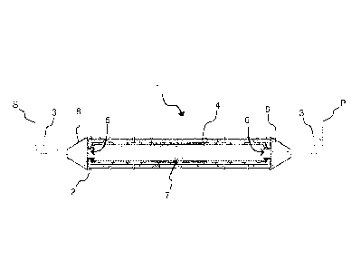
With reference to Figure 1, the facility 1 according to the invention first
5 comprises a vacuum chamber 2 and a means for running the substrate
through
the chamber.
This vacuum chamber 2 is a hermetically-sealable box preferably kept at a
pressure of between 10-8 and 10-3 bar. It has an entry lock and an exit lock
(these
not being shown) between which a substrate S, such as for example a steel
strip,
can run along a given path P in a running direction.
The substrate S may be made to run by any suitable means, depending on
the nature and the shape of said substrate. A rotary support roller 3 on which
a
steel strip can bear may in particular be used.
The vacuum chamber 2 comprises a central casing 4. This is a box
surrounding the substrate path P on a given length in the running direction,
typically 2 to 8 m long. Its walls delimit a cavity. It comprises two
apertures, i.e. a
substrate entry 5 and a substrate exit 6 located on two opposite sides of the
central casing. Preferably the central casing is a parallelepiped which width
is
slightly larger than the substrates to be coated.
The walls of the central casing are suited to be heated. The heating may be
made by any suitable means, such as for example an induction heater, heating
resistors, electron beam. The heating means are suited to heat the inner walls
of
the central casing at a temperature high enough to avoid condensation of metal
or
metal alloy vapors on them. Preferably, the walls of the central casing are
suited to
be heated above the condensation temperatures of the metal elements forming
the coating to be deposited, typically above 500 C, for example between 500 C
and 700 C so as to avoid the condensation of zinc vapors or zinc-magnesium
alloy
vapors. Thanks to these heating means, the inner walls of the central casing
do
not become clogged and the facility does not have to be frequently stopped for
cleaning.
With reference to Figure 2, the central casing 4 also comprises a vapor jet
coater 7, preferably located on one side of the central casing parallel to the
substrate path, beside the face of the substrate S which has to be coated.
This
CA 03084328 2020-06-02
WO 2019/116214
PCT/IB2018/059856
6
coater is suited to spray a metal or metal alloy vapor onto the running
substrate S.
It can advantageously consist of an extraction chamber provided with a narrow
vapor outlet orifice 71, the length of which is close to the width of the
substrate to
be coated.
The vapor outlet orifice 71 may have any suitable shape, such as a slot that
can be adjusted lengthwise and widthwise for example. The possibility of
adapting
its length to the width of the substrate to be coated makes it possible to
minimize
the loss of evaporated metal.
The coater is preferably a sonic vapor jet coater, that is to say a coater
capable of generating a vapor jet of sonic velocity. This type of coater is
also
usually referred to as a JVD (Jet Vapor Deposition) device. The reader may
refer
to the patent application W097/47782 for a fuller description of one variant
of this
type of device. The coater can be coupled to any kind of metallic vapor
generator,
such as, for example, an induction-heated evaporation crucible or an
electromagnetic levitation vapor generator.
Preferably, the central casing is surrounded by insulating panels
themselves preferably surrounded by cooling panels. This allows reducing heat
loss in the vacuum chamber 2 and improving the energy performance of the
central casing.
Thanks to the design of the central casing, in particular the heating means
and the vapor jet coater 7, metal or metal alloy vapor is ejected towards at
least
one side of the substrate and a first layer of metal or metal alloy is formed
on that
side by condensation of a first part of the ejected vapor, without
condensation of
vapor on the inner walls of the central casing.
The vacuum chamber 2 also comprises a vapor trap 8 in the form of an
external casing located at the substrate exit 6 of the central casing 4, i.e.
located
downstream of the central casing in the running direction of the substrate.
Preferably, the vacuum chamber 2 also comprises a second vapor trap 8 in
the form of an external casing located at the substrate entry 5 of the central
casing
4, i.e. located upstream of the central casing in the running direction of the
substrate.
Each vapor trap 8 is a box surrounding the substrate path on a given length
in the running direction, typically 0.2 to 7 m long, for example between 0.5
time
CA 03084328 2020-06-02
WO 2019/116214
PCT/IB2018/059856
7
and 3.5 time the substrate width. Its walls delimit a cavity. It comprises an
inward
opening 9 and an outward opening 10 located on two opposite sides of the vapor
trap and suited to let the substrate enter and exit the vapor trap. The inward
opening 9 is adjacent to the central casing while the outward opening 10 is at
the
opposite.
The walls of the vapor traps 8 are suited to be thermally regulated. The heat
regulation may be made by any suitable means, such as for example a cooling
circuit supplied with a heat transfer fluid such as, for example, water or
nitrogen.
The heat regulation means are suited to maintain the inner walls of the vapor
trap
at a temperature low enough to favor condensation of metal or metal alloys
vapors
on the inner walls, typically below 100 C. Thanks to these heat regulation
means,
the metal or metal alloys vapors escaping the central casing are trapped and
are
not released in the vacuum chamber, which would, in that case, become clogged.
Thanks to the vapor trap 8, the part of the ejected vapor that did not
condensate on the substrate in the central casing 4 and that exits the central
casing is trapped in a cavity of small size compared to the cavity of the
vacuum
chamber 2, which ease the cleaning of the facility. Moreover, that part of the
ejected vapor has some more time to condensate on the substrate in the form of
a
second layer of metal or metal alloy, which increases the deposition yield.
Each vapor trap 8 is in contact with the central casing 4. In particular, the
inward opening 9 of the first vapor trap, respectively of the second vapor
trap, is
aligned with the substrate entry 5 of the central casing, respectively with
the
substrate exit 6 of the central casing, so as to form a passage linking the
central
casing to each vapor trap.
According to one variant of the invention, the vapor trap is of rectangular
shape.
Preferably, the walls of the vapor trap around the inward opening are
perpendicular to the substrate path P. Thanks to this position, these walls
are as
much distant as possible from the aperture 5, 6 of the central casing which
reduces the risk of clogging of the aperture due to metal deposition on cold
walls
of the vapor trap located in the vicinity of the aperture. Thanks to this
position,
vapor entering the vapor trap also more preferably condensates on the
substrate
rather than on the walls, which further increase the deposition yield.
CA 03084328 2020-06-02
WO 2019/116214
PCT/IB2018/059856
8
Preferably, the lower and upper walls of the vapor trap are converging
outwards, i.e. the height of the outward wall is smaller than the height of
the
inward wall. Vapor is thus more efficiently trapped before it reaches the
outward
opening 10.
More preferably, the vapor trap 8 has, in longitudinal cross-section, a
trapezoid shape pointing in a direction opposite to the central casing. In
that
configuration, the trapezium base line is positioned vertically and adjacent
to the
central casing. Thanks to this position of the base line, the walls of the
vapor trap
around the aperture of the central casing are as much distant as possible from
the
aperture which further reduces the risk of clogging of the aperture due to
metal
deposition on cold walls of the vapor trap located in the vicinity of the
aperture. In
that configuration, the edges of the trapezium outwards converge so as to trap
as
much vapor as possible before the vapor exits through the outward opening 10.
According to one variant of the invention, the inner walls of the vapor trap 8
are removable so that cleaning of the facility is further eased. Instead of
stopping
the deposition line during a long time to clean the facility, the clogged
inner walls
can be rapidly removed and replaced by cleaned inner walls.
Tests have been performed on the vacuum deposition facility to assess the
efficiency of a facility comprising two vapor traps when evaporating zinc.
The quantity of zinc evaporated has been obtained by weighting the
evaporation crucible, which feeds the vapor jet coater, before and after the
test.
The quantity of zinc deposited has been obtained by contacting the vapor traps
with an acidic solution to dissolve zinc. The quantity dissolved was then
measured
by Inductively Coupled Plasma. The absence of zinc deposited in the vacuum
chamber has been assessed visually.
A first trial done on a 500mm-wide steel substrate, with a vapor outlet
orifice
71 10mm wider than the steel substrate on each side of the substrate, at a
pressure of 10-1 mBar, has shown that 1.835g of zinc had been deposited in the
vapor traps for 13.5Kg of zinc evaporated and that there was no zinc
deposition in
the vacuum chamber. This corresponds to a deposition yield of 99.99%.
A second trial done on a 300mm-wide steel substrate, in less favorable
conditions, i.e. with a vapor outlet orifice 50mm wider than the steel
substrate on
CA 03084328 2020-06-02
WO 2019/116214
PCT/IB2018/059856
9
each side of the substrate, at a pressure of 10-1 mBar, has shown that 4.915g
of
zinc had been deposited at the inward opening 9 of the vapor traps for 10.5Kg
of
zinc evaporated and that there was no zinc deposition in the vacuum chamber.
This corresponds to a deposition yield of 99.95%.
In comparison, a test performed on a facility without vapor traps in the same
conditions has shown a deposition yield of 99.5%. Despite this high figure,
such a
deposition yield would not be acceptable on an industrial line as this would
lead to
6 Kg of zinc deposited per production hour, that is to say 2 tons of zinc
deposited
after a 2-week production campaign. This deposition yield corresponds to a
build-
up yield of 0.5%, which is 10 to 50 times higher than the build-up yield
observed in
the case of the invention.
The facility according to the invention applies more particularly, but not
solely, to the treatment of metal strips, whether precoated or bare. Of
course, the
process according to the invention may be employed for any coated or uncoated
substrate, such as for example aluminum strip, zinc strip, copper strip, glass
strip
or ceramic strip.