Note: Descriptions are shown in the official language in which they were submitted.
CA 03084423 2020-04-21
WO 2019/105950
PCT/EP2018/082734
AEROSOL-GENERATING ARTICLE HAVING MOUTHPIECE WITH
UPSTREAM CAVITY
The present invention relates to an aerosol-generating article having a
mouthpiece with an
upstream cavity.
Filter cigarettes typically comprise a cylindrical rod of tobacco cut filler
surrounded by a
paper wrapper and a cylindrical filter axially aligned in an abutting end-to-
end relationship with
the wrapped tobacco rod. The cylindrical filter typically comprises a
filtration material
circumscribed by a paper plug wrap. Conventionally, the wrapped tobacco rod
and the filter are
joined by a band of tipping wrapper, normally formed of an opaque paper
material that
circumscribes the entire length of the filter and an adjacent portion of the
wrapped tobacco rod.
Smoking articles having a cavity at the mouth end of their filter section have
also been proposed.
A number of smoking articles in which tobacco is heated rather than combusted
have also
been proposed in the art. In heated smoking articles, an aerosol is generated
by heating an
aerosol generating substrate, such as tobacco. Known heated smoking articles
include, for
example, smoking articles in which an aerosol is generated by electrical
heating or by the transfer
of heat from a combustible fuel element or heat source to an aerosol forming
substrate. During
smoking, volatile compounds are released from the aerosol forming substrate by
heat transfer
from the heat source and entrained in air drawn through the smoking article.
As the released
compounds cool they condense to form an aerosol that is inhaled by the
consumer. Also known
are smoking articles in which a nicotine-containing aerosol is generated from
a tobacco material,
tobacco extract or other nicotine source, without combustion and in some cases
without heating,
for example through a chemical reaction.
It is known to incorporate one or more breakable capsules containing an
additive into the
mouthpiece of an aerosol-generating article, wherein the one or more breakable
capsules are
intended to be broken by the consumer through the application of a compressive
force to the
mouthpiece. The breakage of the one or more capsules releases the additive
contained within
the capsules into the mouthpiece so that it can be entrained in the smoke or
aerosol passing
through the mouthpiece. The consumer may choose to break the one or more
capsules to release
the additive into the mouthpiece before, during or after smoking. For example,
it has been
previously proposed to incorporate one or more breakable capsules containing
an additional
flavourant into the mouthpiece of a smoking article, so that the flavourant
can be released into
the mainstream smoke to provide a modified sensory experience to the consumer.
Breakable capsules are commonly formed with an inner core including the
additive and a
frangible outer shell. Upon the application of a force by the consumer, the
outer shell cracks and
breaks apart so that the inner core is released from the capsule. The breakage
of the outer shell
CA 03084423 2020-04-21
WO 2019/105950
PCT/EP2018/082734
-2-
typically generates an audible sound, which indicates to the consumer that the
capsule has been
broken and the additive released.
During smoking of a smoking article incorporating a breakable capsule, the
smoke drawn
through the mouthpiece from the aerosol-generating substrate will typically
contact the capsule
within the mouthpiece. It has been found that the capsule can be adversely
affected by the heat
and moisture of the smoke. In particular, it has been found that the outer
shell of the capsule can
become softened as a result of contact with the smoke, which can make it more
difficult for the
consumer to break the capsule in order to release the additive. It may also
become difficult for
the consumer to tell whether the capsule has been broken at all, since the
outer shell becomes
too soft to produce an audible sound upon breakage. The same problem can arise
in a heated
aerosol-generating article as a result of the aerosol passing through the
mouthpiece in contact
with the capsule.
It would be desirable to provide an aerosol-generating article incorporating a
novel
mouthpiece arrangement that provides a more reliable and stable means for
releasing an additive,
such as a flavourant, into the mouthpiece during smoking. In particular, it
would be desirable to
provide such an aerosol-generating article having a mouthpiece arrangement
that reduces the
deterioration of a capsule within the mouthpiece as a result of contact with
the mainstream smoke
or aerosol generated during use. It would be further desirable to provide such
an aerosol-
generating article that can be manufactured at high speed using existing
apparatus and methods
without the need for significant modification.
According to the invention there is provided an aerosol-generating article
comprising: an
aerosol-generating substrate; and a mouthpiece in axial alignment with the
aerosol-generating
substrate, the mouthpiece comprising an additive segment of filtration
material comprising one or
more breakable capsules, each breakable capsule comprising an outer shell and
an inner core
containing an additive. The additive segment of filtration material is spaced
downstream from the
aerosol-generating substrate to define an upstream cavity between the aerosol-
generating
substrate and the additive segment of filtration material, wherein the
upstream cavity is
substantially unfilled. The aerosol-generating article further comprises a
wrapper circumscribing
the additive segment of filtration material and the upstream cavity.
As used herein, the term "aerosol-generating substrate" describes a substrate
capable of
releasing, upon heating (including combustion), volatile compounds, which can
form an aerosol.
The aerosol generated from aerosol-generating substrates may be visible or
invisible and may
include vapours (for example, fine particles of substances, which are in a
gaseous state, that are
ordinarily liquid or solid at room temperature) as well as gases and liquid
droplets of condensed
vapours. As used herein, the term "aerosol" encompasses the aerosol produced
upon heating of
a substrate in a heated aerosol-generating article and the smoke produced upon
combustion of
a substrate in a combustible smoking article.
CA 03084423 2020-04-21
WO 2019/105950
PCT/EP2018/082734
-3-
As used herein, the terms "upstream" and "downstream" describe the relative
positions of
elements or portions of elements of an aerosol-generating article in relation
to the direction in
which a user draws on the aerosol-generating article during use. Aerosol-
generating articles
described herein comprise a downstream end and an opposed upstream end. In
use, the
.. consumer draws on the downstream end of the aerosol-generating article. The
downstream end,
which is also described as the mouth end, is downstream of the upstream end,
which may also
be described as the distal end.
As used herein, the term "substantially unfilled" describes a cavity which is
substantially free
from solid or liquid materials. Preferably, less than 5 percent of the
upstream cavity contains solid
or liquid material. More preferably, less than 2 percent of the upstream
cavity contains solid or
liquid material. Most preferably, the upstream cavity is completely unfilled
so that the upstream
cavity contains no solid or liquid material. The aerosol therefore passes
through the upstream
cavity in a substantially unrestricted manner.
Aerosol-generating articles according to the present invention comprise a
mouthpiece
incorporating an upstream cavity between the aerosol-generating substrate and
the additive
segment including the one or more capsules. The provision of this upstream
cavity
advantageously improves the stability of the one or more capsules by
significantly reducing the
adverse effects of the aerosol on the capsules, as described above. This is
due to the fact that
the aerosol has to pass through the upstream cavity before it reaches the
additive segment, which
means that the aerosol is cooler when it comes into contact with the one or
more capsules. There
will also typically be some condensation of the aerosol within the upstream
cavity, which means
that the moisture content of the aerosol is reduced before it reaches the
additive segment.
As a result of the upstream cavity, the aerosol is therefore significantly
cooler and has a
lower moisture content by the time it reaches the one or more capsules within
the additive
segment than if the aerosol had passed directly from the aerosol-generating
substrate into the
additive segment. The aerosol therefore has a lesser effect on the outer shell
of the one or more
capsules. In particular, the softening of the outer shell during use of the
aerosol-generating article
is reduced and preferably minimised so that the one or more capsules within
the additive segment
are found to more reliably break upon the application of a compressive force
by the consumer.
In addition, the one or more capsules retain the ability to generate an
audible sound upon
breakage so that the consumer can more reliably detect the breakage of the one
or more capsules
during use.
The novel mouthpiece arrangement of the present invention can be readily
incorporated
into an aerosol-generating article without significantly impacting the
manufacturing apparatus and
techniques. The mouthpiece components themselves need not be significantly
modified and the
apparatus for assembling the mouthpiece components can be readily adjusted to
provide the
CA 03084423 2020-04-21
WO 2019/105950
PCT/EP2018/082734
-4-
novel arrangement with the upstream cavity, without significantly impacting
the speed of the
assembly process.
The upstream cavity preferably has a length of at least about 3 millimetres,
more preferably
at least about 4 millimetres, most preferably at least about 5 millimetres.
This ensures that the
upstream cavity provides sufficient space for the aerosol to cool and dry to
the desired extent
before reaching the additive segment. Preferably, the upstream cavity has a
length of less than
about 30 millimetres, more preferably less than about 25 millimetres. However,
in certain
embodiments, for example, embodiments in which the upstream cavity is defined
by a plug wrap
as described below, the upstream cavity preferably has a length of less than
about 10 millimetres,
more preferably less than about 7 millimetres. The "length" of the upstream
cavity refers to the
dimension of the upstream cavity in the longitudinal direction of the aerosol-
generating article.
The length of the upstream cavity preferably corresponds to at least about 15
percent of the
total length of the mouthpiece, more preferably at least about 20 percent of
the total length of the
mouthpiece.
The cross-sectional area of the upstream cavity preferably corresponds to at
least about 30
percent of the cross-sectional area of the mouthpiece, more preferably at
least about 50 percent
of the cross-sectional area of the mouthpiece.
In some embodiments of the present invention, the upstream cavity extends from
the
downstream end of the aerosol-generating substrate to the upstream end of the
additive segment.
In such embodiments, there is no intervening material required between the
downstream end of
the aerosol-generating substrate and the upstream end of the additive segment.
In alternative embodiments, the mouthpiece comprises one or more intermediate
segments
of filtration material between the aerosol-generating substrate and the
additive filter segment. For
example, an intermediate segment of filtration material may be provided
adjacent the aerosol-
generating substrate so that the upstream cavity is provided between the
intermediate segment
of filtration material and the additive segment. Alternatively or in addition,
an intermediate
segment of filtration material may be provided adjacent the additive segment.
Preferably the
wrapper of the aerosol-generating articles according to the invention
circumscribes any
intermediate segments of filtration material that are provided between the
aerosol-generating
substrate and the additive segment.
The provision of one or more intermediate segments of filtration material may
advantageously provide further cooling and drying of the aerosol before it
reaches the additive
segment, so that the effect of the aerosol on the one or more capsules can be
further reduced.
The upstream cavity of the mouthpiece of aerosol-generating articles according
to the
invention may be defined by any suitable means.
In certain preferred embodiments of the present invention, the wrapper
circumscribing the
additive segment and the upstream cavity is a plug wrap and the plug wrap
defines the upstream
CA 03084423 2020-04-21
WO 2019/105950
PCT/EP2018/082734
-5-
cavity. The plug wrap therefore extends upstream of the additive segment to
define the upstream
cavity. In such embodiments, the plug wrap preferably has a basis weight of at
least about 50
grams per square metre, more preferably at least about 70 grams per square
metre. This
provides a relatively stiff plug wrap that maintains the structural rigidity
of the upstream cavity and
helps to prevent collapse of the upstream cavity during manufacture, or during
use. For example,
the plug wrap may have a basis weight of between about 50 grams per square
metre and about
120 grams per square metre, or between about 70 grams per square metre and
about 110 grams
per square metre.
The use of the plug wrap to define the upstream cavity may simplify the
manufacturing
process, since no additional components are required to be incorporated into
the mouthpiece.
In embodiments in which the plug wrap defines the upstream cavity, the length
of the
upstream cavity is typically limited in order to retain the structural
integrity of the mouthpiece.
Furthermore, in such embodiments, the upstream cavity will not significantly
contribute to the RTD
of the mouthpiece. The desired level of RTD must therefore be provided by the
additive segment
and any other mouthpiece components downstream of the upstream cavity. In
such
embodiments, the upstream cavity therefore preferably has a length of no more
than 7 millimetres,
for example a length of between about 5 millimetres and about 7 millimetres.
In such embodiments, the length of the upstream cavity preferably corresponds
to less than
about 25 percent of the overall length of the mouthpiece, more preferably less
than about 20
percent of the overall length of the mouthpiece. The length of the upstream
cavity in these
embodiments is therefore preferably between about 15 percent and about 25
percent of the
overall length of the mouthpiece.
In alternative preferred embodiments, the mouthpiece comprises a hollow tube
segment
between the substrate and the filter segment, wherein the hollow tube segment
defines the
upstream cavity. The use of a hollow tube segment to define the upstream
cavity may
advantageously make the upstream cavity more resistant to collapse or
deformation during
manufacture and subsequent use of the aerosol-generating article. In some
cases, the hollow
tube segment may additionally contribute to the overall RTD of the mouthpiece.
The hollow tube segment may be formed from any suitable material. For example,
the
hollow tube segment may be formed from an annular shaped segment of filtration
material, such
as cellulose acetate, having a hollow core extending from the upstream end of
the annular shaped
segment of filtration material to the downstream end of the annular shaped
segment of filtration
material. Such segments may be referred to as a hollow acetate tube.
Preferably, the filtration material of the annular shaped segment comprises
fibres of
between approximately 2.1 denier per filament (dpf) and approximately 12 dpf,
more preferably
between approximately 3.0 denier per filament (dpf) and approximately 10 dpf.
Preferably, the
filtration material of the annular shaped segment comprises fibres of between
approximately
CA 03084423 2020-04-21
WO 2019/105950
PCT/EP2018/082734
-6-
30000 total denier (td) and approximately 50000 td, more preferably between
35000 total denier
(td) and approximately 45000 td.
In a preferred embodiment, the filtration material of the annular shaped
segment comprises
fibres of approximately 40000 td. Preferably, the hollow tube segment
comprises one or more
plasticisers. Suitable plasticisers include triacetin, triethyl citrate and
triethylenglycol di-acetate.
Preferably, the plasticiser is present in the annular shaped segment in an
amount of between
about 8 and about 25 percentage weight, more preferably between about 10 and
about 22
percentage weight. This can help the hollow tube segment to maintain its
structural rigidity in the
mouthpiece.
Preferably, where the hollow tube is an annular shaped segment of filtration
material such
as a hollow acetate tube, the wall thickness of the hollow tube segment is at
least about 0.3
millimetres, more preferably at least about 0.5 millimetres. Alternatively or
in addition, the wall
thickness of the hollow tube segment in such embodiments is less than about
1.2 millimetres,
more preferably less than about 1.1 millimetres. In some preferred
embodiments, the wall
thickness of the hollow tube segment is between about 0.5 millimetres and
about 1.1 millimetres.
In some other preferred embodiments, the hollow tube segment is formed from a
paper
material. More preferably, the hollow tube segment is formed from a plurality
of overlapping paper
layers, such as a plurality of parallel wound paper layers or a plurality of
spirally wound paper
layers. Forming the hollow tube segment from a plurality of overlapping paper
layers can help to
improve resistance to collapse or deformation.
Preferably, each hollow tube segment comprises at least two paper layers.
Alternatively,
or in addition, each hollow tube segment preferably comprises fewer than
eleven paper layers.
Preferably, at least one of the paper layers is made from a paper with a basis
weight of at
least about 100 grams per square metre.
Preferably, where the hollow tube segment is formed of paper layers, the wall
thickness of
the hollow tube segment is at least about 100 micrometres. More preferably,
the wall thickness
of the hollow tube segment is at least about 200 micrometres. Alternatively,
or in addition, the
wall thickness of the hollow tube segment in such embodiments is less than
about 300
micrometres. Preferably, the wall thickness of the hollow tube segment is less
than about 270
micrometres. In some preferred embodiments, the wall thickness of the hollow
tube segment is
from about 100 micrometres to about 300 micrometres, preferably from 200
micrometres to 270
micrometres.
Where the upstream cavity is defined by a hollow tube segment, as described
above, the
length of the upstream cavity may be significantly greater than where the
upstream cavity is
defined by a plug wrap. For example, the upstream cavity may be up to 30
millimetres in length,
or up to 25 millimetres in length. This is due to the structural rigidity
provided by the hollow tube
segment, which reduces the risk of collapse of the upstream cavity.
CA 03084423 2020-04-21
WO 2019/105950
PCT/EP2018/082734
-7-
In such embodiments, the length of the upstream cavity may correspond to up to
about 85
percent of the overall length of the mouthpiece, or up to about 70 percent of
the overall length of
the mouthpiece. The length of the upstream cavity in these embodiments is
therefore preferably
between about 15 percent and about 85 percent of the overall length of the
mouthpiece.
The additive segment of the mouthpiece of aerosol-generating articles
according to the
present invention comprises a segment of filtration material containing one or
more breakable
capsules. The additive segment preferably has a length of at least about 8
millimetres, more
preferably at least about 10 millimetres, most preferably about 12 millimetres
long. Preferably,
the additive segment has a length of less than about 16 millimetres, more
preferably less than
about 14 millimetres.
In some embodiments of the present invention, for example where the upstream
cavity is
defined by the plug wrap, the length of the additive segment may be greater
than the length of
the upstream cavity. For example, the length of the additive segment may be at
least 1.5 times
the length of the upstream cavity, more preferably at least 2 times the length
of the upstream
cavity.
In other embodiments of the present invention, for example where the upstream
cavity is
defined by a hollow tube segment, the length of the additive segment may be
lower than or
substantially the same as the length of the upstream cavity. For example, the
length of the
additive segment may be between about 0.25 times and about 1 times the length
of the upstream
cavity.
The length of the additive segment preferably corresponds to at least about 20
percent of
the overall length of the mouthpiece, more preferably at least about 30
percent. Preferably, the
length of the additive segment corresponds to less than about 85 percent of
the overall length of
the mouthpiece, more preferably less than about 60 percent.
The additive segment preferably comprises a plug of fibrous filtration
material, such as
cellulose acetate tow or paper. A filter plasticiser may be applied to the
fibrous filtration material
in a conventional manner, by spraying it onto the separated fibres.
The additive segment may include a single breakable capsule. For example, in
one
preferred embodiment, the additive segment comprises a single breakable
capsule within a plug
of cellulose acetate tow. Where a single breakable capsule is provided, the
breakable capsule is
preferably substantially spherical with a diameter of between about 2
millimetres and about 5
millimetres. The single capsule is preferably provided approximately centrally
along the length of
the additive segment.
The additive segment may alternatively comprise a plurality of breakable
capsules
dispersed through the segment. The plurality of breakable capsules may all
contain the same
additive, or the breakable capsules may contain two or more different
additives.
CA 03084423 2020-04-21
WO 2019/105950
PCT/EP2018/082734
-8-
The additive contained in the one or more breakable capsules may include at
least one
flavourant comprising at least one of menthol, linalool, thymol, eucalyptol,
methyl salicylate, and
combinations thereof. Additionally, or alternatively, the at least one
flavourant may comprise at
least one of lemon oil, peppermint oil, parsley oil, champignon essence, green
tea extract, oolong
.. tea extract, mugwort drawing-extract, apple extract, kaki-fruit extract,
ginger essence, and
combinations thereof. Suitable flavourants are described in US-6426089-131.
The at least one flavourant may comprise a diluent. The diluent may comprise
at least one
of palm oil and a medium-chain triglyceride.
Many naturally occurring flavourants can be obtained either by extraction from
a natural
source or by chemical synthesis if the structure of the compound is known. The
flavourants can
be extracted from a part of a plant or an animal by physical means, by
enzymes, or by water or
an organic solvent, and thus include any extractive, essence, hydrolysate,
distillate, or absolute
thereof. Plants that can be used to provide flavourants include, but are not
limited to, those
belonging to the families, Lamiaceae (for example, mints), Apiaceae (for
example, anise, fennel),
Lauraceae (for example, laurels, cinnamon, rosewood), Rutaceae (for example,
citrus fruits),
Myrtaceae (for example, anise myrtle), and Fabaceae (for example, liquorice).
Non-limiting
examples of sources of flavourants include mints such as peppermint and
spearmint, coffee, tea,
cinnamon, clove, ginger, cocoa, vanilla, chocolate, eucalyptus, geranium,
agave, juniper, lemon
balm, basil, cinnamon, lemon basil, chive, coriander, lavender, sage, tea,
thyme and caraway.
The term "mints" is used to refer to plants of the genus Mentha. Suitable
types of mint leaf may
be taken from plant varieties including but not limited to Mentha piperita,
Mentha arvensis, Mentha
niliaca, Mentha citrata, Mentha spicata, Mentha spicata crispa, Mentha
cordifolia, Mentha
longifolia, Mentha pulegium, Mentha suaveolens, and Mentha suaveolens
variegate.
The additive contained in the one or more breakable capsules may provide one
or more
sensory effects other than a flavour sensation, such as a cooling or a warming
sensation, a
tingling sensation, a numbing sensation, effervescence, increased salivation,
cough suppression,
and combinations thereof. These sensory effects may be provided by one or more
flavourants,
including the flavourants listed above. Additionally, or alternatively, the
additive may comprise at
least one non-flavourant material which provides one or more of these sensory
effects without
providing a flavour sensation. For example, suitable compounds that produce a
cooling effect and
can be used as an active material include, but are not limited to, the family
of carboxamide
compounds, such as the Wilkinson-Sword (WS) compounds WS-3 (N-Ethyl-p-menthane-
3-
carboxamide), WS-23 (2-lsopropyl-N,2,3-trimethylbutyramide), WS-5 [Ethyl 3-(p-
menthane-3-
carboxamido)acetate], WS-27 (N-Ethyl-2,2-diisopropylbutanamide),
WS-14 [N-
([ethoxycarbonyl]methyl)-p-menthane-3-carboxamide], and WS-116 (N-(1,1-
Dimethy1-2-
hydroxyethyl)-2,2-diethylbutanamide). A suitable compound that provides a
cough suppression
effect is benzonatate.
CA 03084423 2020-04-21
WO 2019/105950
PCT/EP2018/082734
-9-
The one or more breakable capsules are preferably provided at least about 2
millimetres
from the upstream end of the additive segment, more preferably at least about
4 millimetres. This
maximises the separation of the one or more capsules from the aerosol-
generating substrate
which in turn maximises the reduction in temperature and moisture content of
the aerosol before
it reaches the capsules. In addition, the positioning of the one or more
capsules away from the
upstream end of the additive segment ensures that the additive is effectively
dispersed through
the additive segment after it has been released from the one or more capsules
and does not leak
into the upstream cavity.
The one or more breakable capsules in the additive segment are preferably
provided at
least about 5 millimetres from the downstream end of the aerosol-generating
substrate, more
preferably at least about 8 millimetres from the downstream end of the aerosol-
generating
substrate and most preferably at least about 10 millimetres from the
downstream end of the
aerosol-generating substrate. For example, the one or more breakable capsules
in the additive
segment may be provided at a distance of between about 5 millimetres and about
12 millimetres
from the downstream end of the aerosol-generating substrate.
The mouthpiece of aerosol-generating articles according to the invention may
include only
the additive segment downstream of the upstream cavity. Alternatively, the
mouthpiece may
further comprise a downstream segment of filtration material downstream of the
additive segment.
Preferably, the downstream segment of filtration material are in an abutting
end-to-end
relationship with the additive segment.
Where present, the downstream segment of filtration material preferably
comprises one or
more additional breakable capsules, which may be the same as the one or more
breakable
capsules in the additive segment, or different.
Alternatively or in addition to the provision of one or more additional
breakable capsules
within the downstream segment of filtration material, the downstream segment
of filter material
may optionally incorporate a downstream recess. Preferably, the downstream
recess provides a
mouth end recess to the mouthpiece. Where present, the recess may have a
length of between
about 3 millimetres and about 8 millimetres, most preferably about 5
millimetres.
The downstream segment of filtration material preferably has a length of at
least about 8
millimetres, more preferably at least about 9 millimetres, most preferably
about 10 millimetres
long. Preferably, the downstream segment has a length of less than about 14
millimetres, more
preferably less than about 12 millimetres. The length of the downstream
segment of filtration
material may be approximately equal to the length of the additive segment.
Alternatively, the
additive segment may be at least about 1 millimetre longer than the downstream
segment of
filtration material, or at least about 2 millimetres longer. Alternatively,
the additive segment may
be at least 1 millimetre shorter than the downstream segment of filtration
material, or at least 2
millimetres longer.
CA 03084423 2020-04-21
WO 2019/105950
PCT/EP2018/082734
-10 -
The downstream segment of filtration material may be formed of the same
filtration material
as the additive segment, or a different filtration material. In one preferred
embodiment, both the
additive segment and the downstream segment of filtration material are formed
of plugs of
cellulose acetate tow.
The downstream segment of filtration material may be selected to provide a
required
resistance to draw (RTD). Preferably, the downstream segment of filtration
material has an RTD
of at least about 5 mm WG (water gauge). Preferably, the downstream segment of
filtration
material has an RTD of less than about 120 mm WG, more preferably less than
about 80 mm
WG. RTD is measured in accordance with ISO 6565:2002.
Preferably, the mouthpiece of aerosol-generating articles according to the
present invention
further comprises one or more ventilation zones provided over the additive
segment. Preferably,
the one or more ventilation zones are provided upstream of the one or more
capsules in the
additive segment. The provision of an upstream ventilation zone introduces
cooler air into the
aerosol upstream of the one or more capsules. This advantageously provides an
additional
cooling effect on the aerosol to further minimise the impact of the aerosol on
the breakability of
the outer shell. In addition, the air introduced into the mouthpiece through
the one or more
ventilation zones dilutes the aerosol, thereby reducing the moisture content.
This further
minimises the impact of the aerosol on the outer shell.
The one or more ventilation zones are preferably provided at least about 1
millimetre
upstream of the one or more capsules in the additive segment, more preferably
at least about 2
millimetres upstream of the one or more capsules. This ensures that the
cooling air is introduced
into the mouthpiece sufficiently upstream of the one or more capsules that the
cooling air can be
mixed into the aerosol.
The one or more ventilation zones are preferably provided at least about 2
millimetres from
the upstream end of the additive segment, more preferably at least about 3
millimetres from the
upstream end of the additive segment.
The ventilation level of the additive segment is preferably between about 20
percent and
about 80 percent, as measured in accordance with ISO 9512:2002.
The one or more ventilation zones may be provided by one or more
circumferential rows of
perforations in the wrapper or wrappers circumscribing the additive segment.
For example, an
on-line laser perforation process may be used to form the required ventilation
zones in the
wrapper.
Alternatively or in addition to the one or more ventilation zones provided
over the additive
segment, as described above, the mouthpiece may comprise one or more
ventilation zones
provided over the upstream cavity. The provision of one or more ventilation
zones over the
upstream cavity introduces air into the upstream cavity during smoking. This
advantageously
increases the turbulence of the aerosol within the upstream cavity and
increases the residence
CA 03084423 2020-04-21
WO 2019/105950
PCT/EP2018/082734
-11-
time of the aerosol within the cavity. As a result, the aerosol has more time
to cool before reaching
the one or more breakable capsules in the additive segment.
As described above, the mouthpiece of aerosol-generating articles according to
the present
invention comprises a wrapper circumscribing the upstream cavity and the
additive segment. The
wrapper is preferably a plug wrap that circumscribes the additive cavity and
circumscribes or
defines the upstream cavity. Where the plug wrap defines the upstream cavity,
as described
above, the plug wrap is preferably a stiff plug wrap with a relatively high
basis weight, as
described. Where a downstream segment of filtration material is provided
downstream of the
additive segment, the plug wrap preferably also circumscribes the downstream
segment of
filtration material to combine the mouthpiece components. Similarly, where one
or more
intermediate segments of filtration material are provided between the aerosol-
generating
substrate and the additive segment, the plug wrap preferably circumscribes the
intermediate
segments of filtration material to combine all of the mouthpiece components.
Preferably, the wrapper does not extend about any part of the aerosol-
generating
substrate. Preferably, the wrapper extends between the downstream end of
the aerosol
generating substrate and the downstream end of the mouthpiece. Utilising a
wrapper which does
not extend about any part of the aerosol-generating substrate advantageously
simplifies the
construction of the aerosol-generating article, since it allows the mouthpiece
to be formed
separately from the aerosol-generating substrate and then subsequently
attached thereto later in
the manufacturing process. Additionally, by utilising a wrapper which does not
extend about any
part of the aerosol-generating substrate it is possible to construct the
mouthpiece and the aerosol-
generating substrate with the same external diameter, which facilitates
connecting the
mouthpiece and the aerosol-generating substrate together (for example, with a
tipping wrapper).
To connect the mouthpiece to the aerosol-generating substrate, aerosol-
generating
articles according to the present invention may include a tipping wrapper
circumscribing the
mouthpiece and at least a portion of the aerosol-generating substrate. The
tipping wrapper may
comprise paper having a basis weight of less than about 70 grams per square
metre, preferably
less than about 40 grams per square metre. The tipping wrapper preferably has
a basis weight
of more than about 20 grams per square metre.
The mouthpiece of aerosol-generating articles according to the invention
preferably has
an overall length of between about 20 millimetres and about 35 millimetres, as
measured between
the downstream end of the aerosol-generating substrate and the mouth end of
the aerosol-
generating article. For example, the mouthpiece may have an overall length of
about 27
millimetres.
Preferably, the aerosol-generating substrate of aerosol-generating articles
according to
the present invention comprises a wrapped rod of tobacco which can be
combusted to form
smoke. Alternatively, the aerosol-generating substrate may be a source of
tobacco material,
CA 03084423 2020-04-21
WO 2019/105950
PCT/EP2018/082734
-12-
tobacco extract, or other nicotine source, which can be heated, without
combustion, to generate
an aerosol.
The aerosol-generating substrate may have a length of between about 45
millimetres and
about 65 millimetres. For example, the aerosol-generating substrate may have a
length of about
56 millimetres.
Aerosol generating articles according to the present invention may be filter
cigarettes or
other smoking articles in which the aerosol generating substrate comprises a
tobacco material
that is combusted to form smoke. Therefore, in any of the embodiments
described above, the
aerosol generating substrate may comprise a tobacco rod.
Alternatively, aerosol generating articles according to the present invention
may be articles
in which a tobacco material is heated to form an aerosol, rather than
combusted. In one type of
heated aerosol generating article, a tobacco material is heated by one or more
electrical heating
elements to produce an aerosol. In another type of heated aerosol-generating
article, an aerosol
is produced by the transfer of heat from a combustible or chemical heat source
to a physically
separate tobacco material, which may be located within, around or downstream
of the heat
source. The present invention further encompasses aerosol-generating articles
in which a
nicotine-containing aerosol is generated from a tobacco material, tobacco
extract, or other
nicotine source, without combustion, and in some cases without heating, for
example through a
chemical reaction.
The aerosol-generating article may have an overall length of between about
40mi11imetres
and about 90 millimetres, as measured between the upstream end of the aerosol-
generating
article and the mouth end of the aerosol-generating article. For example, the
aerosol-generating
article may have an overall length of about 83 millimetres.
The aerosol-generating article may have an external diameter (including any
tipping
wrapper that may be present) of between about 4 millimetres and about 9
millimetres. For
example, the aerosol-generating article may have a diameter of about 7.8
millimetres. In other
preferred embodiments, the aerosol-generating article may have a diameter of
less than about
7.1 millimetres, or less than about 6 millimetres. The present invention finds
particular application
in mouthpieces for "thin" or "slim" aerosol-generating article having a
diameter of less than about
7.1 millimetres. In such aerosol-generating articles the deterioration of
capsules in the
mouthpiece as a result of contact with the aerosol during use can be
particularly problematic.
The invention will now be further described, by way of example only, with
reference to the
accompanying drawings in which:
Figure 1 shows a perspective view of an aerosol-generating article in
accordance with the
present invention; and
Figure 2 shows a longitudinal cross-sectional view of the aerosol-generating
article of
Figure 1.
CA 03084423 2020-04-21
WO 2019/105950
PCT/EP2018/082734
-13-
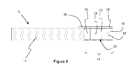
Figures 1 and 2 illustrate an aerosol-generating article 10 in accordance with
the present
invention. The aerosol-generating article 10 comprises a wrapped tobacco rod
12 of tobacco cut
filler which is attached at one end to an axially aligned mouthpiece 14. A
band of tipping paper
16 circumscribes the mouthpiece 14 and a portion of the wrapped tobacco rod 12
to join together
the two components of the aerosol-generating article 10.
As shown in Figure 2, the mouthpiece 14 comprises a first filter segment 18
and a second
filter segment 20. The first filter segment 18 is provided at the mouth end of
the mouthpiece 14
and comprises a wrapped plug of cellulose acetate tow containing a centrally
positioned capsule
22. The first filter segment 18 has a length of 10 millimetres. The second
filter segment 20 is
provided upstream of the first filter segment 18 and the downstream end of the
second filter
segment 20 abuts the upstream end of the first filter segment 18. The second
filter segment 20
comprises a wrapped plug of cellulose acetate tow containing a centrally
positioned capsule 24.
Each of the capsules 22,24 comprises an inner core of a flavourant additive
and a frangible
outer shell.
As shown in Figure 2, the second filter segment 20 is spaced apart from the
wrapped
tobacco rod 12 in the longitudinal direction and an upstream cavity 26 is
provided between the
second filter segment 20 and the wrapped tobacco rod 12. The upstream cavity
26 is unfilled and
has a length of 5 millimetres.
The upstream cavity 26 is defined by a combining plug wrap 28 which
circumscribes the
first filter segment 18 and the second filter segment 20 and extends upstream
of the second filter
segment 20 by 5 millimetres. The combining plug wrap 28 therefore does not
extend over the
wrapped tobacco rod 12. The tipping wrapper 16 overlies the combining plug
wrap 28 to connect
the mouthpiece 14 and the wrapped tobacco rod 12, as shown in Figure 2.
The combining plug wrap 28 is formed of a sheet of a paper material having a
basis weight
of at least 70 grams per square metre such that the combining plug wrap 28 has
a relatively high
stiffness.
The aerosol-generating article 10 further comprises a ventilation zone 30 at a
location
along the second filter segment 20, upstream of the capsule 24. The
ventilation zone 30
comprises a row of perforations extending through the tipping wrapper 16 and
the combining plug
wrap 28.
During smoking of the aerosol-generating article 10, the mainstream smoke
generated
from the tobacco in the wrapped rod 12 passes into the upstream cavity 26
before passing through
the second filter segment 20 and coming into contact with the capsule 24. The
smoke continues
downstream and passes through the first filter segment 18 in contact with the
capsule 22. The
mainstream smoke cools down as it passes through the upstream cavity 26 and
the effect of the
mainstream smoke on the capsules 22,24 is therefore minimised. The capsules
22,24 retain their
CA 03084423 2020-04-21
WO 2019/105950 PCT/EP2018/082734
-14-
frangibility during smoking and can still be broken by the consumer after
smoking to produce an
audible sound.