Note: Descriptions are shown in the official language in which they were submitted.
COMMUNICATION METHOD AND APPARATUS
TECHNICAL FIELD
[0001] The present invention relates to the communications field, and in
particular,
to communication method and apparatus.
BACKGROUND
[0002] Development of mobile services has higher requirements for a data
rate and
a capacity in wireless communication. To support a higher data rate and a
larger user
capacity, multi-beam communication is performed in a next-generation
communications system (for example, NR (new radio)). Before communicating with
a
terminal, a base station first needs to perform uplink synchronization and
downlink
synchronization. In a downlink synchronization process, the base station sends
a
downlink synchronization signal through a plurality of transmit beams, and the
terminal
receives and detects the downlink synchronization signal through one or more
receive
beams, and determines an optimal pair of downlink transmit beam and receive
beam, a
.. downlink time, and system information. The uplink synchronization is
completed with
the help of a random access process. The terminal first sends a random access
signal,
and the base station detects the random access signal, to obtain an optimal
pair of
uplink transmit beam and receive beam, an uplink time, and the like, and
implements
uplink synchronization between the base station and the terminal.
[0003] In a current new radio (NR) communications system, there is no
suitable
method for determining a frequency position of a random access resource.
Therefore,
when the terminal sends the random access signal, the terminal shoots in the
dark on a
random access resource, and beams may not match when the base station receives
the
random access signal, leading to relatively low efficiency of the random
access process.
1
Date recue / Date received 2021 -1 1-08
SUMMARY
[0004] Embodiments of the present invention provide communication method
and
apparatus, thereby determining a frequency position of a random access
resource in a
next-generation communications system.
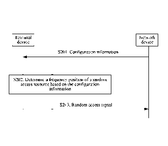
[0005] According to a first aspect, an embodiment of the present invention
provides
a random access signal sending method, including: receiving, by a terminal
device,
configuration information from a network device, where the configuration
information
includes at least one of an initial frequency offset, a random access resource
configuration period, an uplink channel bandwidth, a bandwidth of a random
access
resource, a time period of a random access resource, a time period of the
random access
resource, and a frequency index of the random access resource; determining, by
the
terminal device, a frequency position of the random access resource based on
the
configuration information; and sending a random access signal to the network
device at
the frequency position of the random access resource. Optionally, the time
period is
also referred to as a slot.
[0006] The random access resource is a time-frequency resource used for
transmitting a random access preamble, and the random access resource is a
time-frequency resource set including a time domain resource and a frequency
domain
resource. The random access resource occupies a particular time in time domain
and
occupies a particular bandwidth in frequency domain. A random access resource
configuration pattern represents position distribution of all available random
access
resources in a specified time-frequency resource set. The random access
resource
configuration period is a time length of the time-frequency resource set, and
the time
length may be represented through a quantity of system frames, subframes,
slots,
mini-slots, or OFDM (orthogonal frequency division multiplexing) symbols. The
random access resource configuration pattern periodically appears. The
frequency
position of the random access resource represents an absolute position of the
random
access resource in frequency domain, and the frequency position of the random
access
resource uses an RB (resource block) or an RB group (resource block group) as
a
2
Date recue / Date received 2021 -1 1-08
granularity. For example, with a given bandwidth of the random access
resource, the
frequency position of the random access resource may be represented through a
starting
RB position or a middle RB position of the random access resource. The initial
frequency offset represents a frequency starting position of an initial
available random
access resource in the random access resource configuration pattern, for
example, is
represented through a starting RB position. The uplink channel bandwidth
represents a
system bandwidth for sending uplink data, and the bandwidth may be represented
through a quantity of RBs. The bandwidth of the random access resource
represents a
bandwidth size occupied by the random access resource in frequency domain. For
example, the bandwidth of the random access resource may be represented
through a
quantity of RBs. The time period of the random access resource represents a
time
length of the random access resource in time domain, and the time length may
be
represented through a quantity of subframes, slots, or OFDM symbols. Also, the
time
period of the random access resource represents an absolute time position of
the
random access resource, including a system frame number, a subframe number in
a
system frame, a slot number in a subframe, an OFDM symbol in a slot, or a time
position in an OFDM symbol (where a basic time unit is used as a granularity);
or
represents a relative position of the random access resource within the random
access
resource configuration period, to be specific, the random access resource
exists on T
time positions within the random access resource configuration period, where
the time
period of the random access resource refers to relative positions 0, 1, ...,
and T-1. The
frequency index of the random access resource represents an index of the
random
access resource in frequency domain. The terminal device selects a random
access
preamble from a random access preamble set and sends the random access
preamble at
the determined frequency position of the random access resource. For a method
for
selecting the random access preamble, refer to descriptions in the prior art,
and this
application imposes no limitation thereon.
[0007] The terminal device may be directly notified by the network
device of
values of various parameters in the configuration information, or the network
device
sends indexes of the parameters to the terminal device. The parameters in the
3
Date recue / Date received 2021 -1 1-08
configuration information may be carried in one message, or may be
respectively
carried in a plurality of messages. For example, the network device sends the
time
period of the random access resource through at least one of RRC (radio
resource
control) signaling, SI (system information), RMSI (remaining minimum system
information), NR SIB I (new radio system information block type 1), MAC CE
(media
access control control element) signaling, DCI (downlink control information),
a PBCH
(physical broadcast channel), and a PDCCH order (physical downlink control
channel
order). The time period of the random access resource may be an absolute time,
or may
be an index of the time period (for example, a system frame number, a subframe
number in a system frame, a slot number in a subframe, or an OFDM symbol in a
slot).
[0008] The random access resource configuration period (PRACH
configuration
period/PRACH period/PRACH density) is also referred to as a random access
period.
Optionally, the random access resource is also referred to as PRACH. The
random
access resource configuration period includes a plurality of random access
resources in
a dimension of time, frequency, preamble, or sequence, and these resources
constitute a
random access resource configuration pattern. The random access resource
configuration period is also a time interval at which the random access
resource
configuration pattern recurs. A random access resource within a random access
resource
configuration period is associated with all actually transmitted downlink
signals in a
downlink signal set. It may be understood that the random access resource
associated
with the downlink signals recurs within the random access resource
configuration
period.
[0009] Based on the foregoing descriptions, the terminal device
determines the
frequency position of the random access resource based on at least one of the
initial
frequency offset, the random access resource configuration period, the uplink
channel
bandwidth, the bandwidth of the random access resource, the time period of the
random
access resource, and the frequency index of the random access resource that
are
configured by the network device, and the terminal device sends the random
access
signal to the network device at the determined frequency position. In this
way, the
terminal device is prevented from shooting in the dark on a random access
resource
4
Date recue / Date received 2021 -1 1-08
when sending the random access signal, thereby improving efficiency of a
random
access process.
[0010] In a possible design, the configuration information further
includes a
frequency hopping offset.
[0011] Random access resources in the random access resource configuration
pattern are distributed at equal intervals in frequency domain, and the
frequency
hopping offset represents a frequency position difference between two random
access
resources adjacent to each other within a same time period.
[0012] In a possible design, the determining, by the terminal device a
frequency
position of the random access resource based on the configuration information
specifically includes:
tRA ITRA dmod2 =0
when F RB = f, ,õ, + N RA X f RA ; or
Ltõ / TRA j mod 2 =1 F =N ¨NRAx(fRA +1)
RB RB Lan
when , where
Lj represents a rounding down operation; mod represents a modulo
operation; FRB is the frequency position of the random access resource, and
uses an
RB as a granularity; fsfaõ is the initial frequency offset, and may be
represented
through a starting RB position of the initial available random access resource
in the
random access resource configuration pattern; TRA is the random access
resource
configuration period; NRB is the uplink channel bandwidth; N, is the bandwidth
of
the random access resource; t, is the time period of the random access
resource; and
f, is the frequency index of the random access resource.
[0013] Based on the foregoing descriptions, the terminal device sends
the random
access signal to the network device through frequency hopping. In this way,
the
terminal device can implement frequency diversity and improve transmission
reliability
of the random access signal.
[0014] In a possible design, the determining, by the terminal device, a
frequency
position of the random access resource based on the configuration information
5
Date recue / Date received 2021 -1 1-08
specifically includes:
when
LtR, T RA j mod 2 d
= 0 fRii mod 2 = 0
an
FRB f start N RA x LfR, /
when
LtRA / T RA j mod 2 d
= 0 fRA mod 2 = 1
an
F RB = N RB f stolli ¨ N RA X 1L f RA I 2 j+
when
LtRA / T RA j mod 2 = 1 d fRA mod 2 = 0
an
FRB = N RB ¨ fstort¨ N RA X (L f RA I 2 j+
; or
when
It IT jmod2=1 and f mod 2 = 1 FRB f start N RA x LfRA / 2
RA RA
where
L j represents a rounding down operation, mod represents a modulo
operation, FR, is the frequency position of the random access resource, fsta,
is the
initial frequency offset, TRA is the random access resource configuration
period, NRR
is the uplink channel bandwidth, NRA is the bandwidth of the random access
resource,
tRA is the time period of the random access resource, and LA is the frequency
index
.. of the random access resource.
[0015] In a possible design, the determining, by the terminal device, a
frequency
position of the random access resource based on the configuration information
specifically includes:
L' / T j mod 2 = 0 FRB = fsfort+NRAx f
when L RA RA RA ; or
It IT jmod2=1
when RB ( kJ f start f offset N RAx fRA) mod N RB , where
Lj represents a rounding down operation, mod represents a modulo
operation, FRB is the frequency position of the random access resource, fstart
is the
initial frequency offset, TRA is the random access resource configuration
period, NRR
is the uplink channel bandwidth, 1VRA is the bandwidth of the random access
resource,
6
Date recue / Date received 2021 -1 1-08
tõ is the time period of the random access resource, fRA is the frequency
index of
the random access resource, and f is the frequency hopping offset.
[0016] In a possible design, in all of the foregoing formulas, TRA is an
absolute
time length of the random access resource configuration period, and t, is an
absolute
time of the random access resource. For example, the absolute time length of
the
random access resource configuration period is one of 5 ms, 10 ms, 20 ms, 40
ms, 80
ms, 160 ms, 320 ms, and 640 ms.
[0017] In a possible design, in all of the foregoing formulas, AA is a
frequency
index of the random access resource in an initial access uplink channel
bandwidth part;
or f, is a frequency index of the random access resource in an uplink channel
bandwidth; or fs,,õ is a preset value 0.
[0018] In a possible design, the configuration information further
includes a
mapping relationship between at least one actually sent downlink signal and a
random
access resource in a random access resource configuration pattern.
[0019] The at least one actually sent downlink signal is a signal sent by
the network
device for downlink synchronization, and the downlink signal may be at least
one of a
synchronization signal block (SS block) and a channel state information
reference
signal (CSI-RS). The SS block may correspond to one or more OFDM symbols. The
SS
block includes at least one of the following: a primary synchronization signal
(PSS), a
secondary synchronization signal (SSS), a physical broadcast signal (PBCH),
and a
demodulation reference signal (DMRS). The SS block may also be referred to as
an
SS/PBCH block. A plurality of signals in the SS block or the SS/PBCH block may
be
sent through a same antenna port. The mapping relationship is also referred to
as an
association relationship, and the at least one actually sent downlink signal
may have an
association relationship with a plurality of random access resources, or the
at least one
actually sent downlink signal has a mapping relationship with only one random
access
resource. Based on different mapping relationships, the terminal device
determines the
7
Date recue / Date received 2021 -1 1-08
random access resource in different methods.
[0020] In a possible design, the configuration information further
includes a format
of the random access preamble and/or at least one actually sent downlink
signal.
[0021] In a possible design, the configuration information further
includes a frame
structure type, uplink/downlink configuration information, or a duplex mode.
[0022] The frame structure type includes a TDD frame or an FDD frame.
The
uplink/downlink configuration information includes an uplink slot, a downlink
slot, a
quantity of undetermined slots, and period information. The duplex mode
includes full
duplex, TDD, or FDD.
[0023] According to a second aspect, this application provides a random
access
signal receiving method, including:
sending, by a network device, configuration information to a terminal
device, where the configuration information includes at least one of an
initial frequency
offset, a random access resource configuration period, an uplink channel
bandwidth, a
bandwidth of a random access resource, and a frequency index of the random
access
resource; determining, by the network device, a frequency position of the
random
access resource based on the configuration information; and receiving, by the
network
device, a random access signal from the terminal device at the frequency
position of the
random access resource.
[0024] The terminal device may be directly notified by the network device
of
values of various parameters in the configuration information, or the network
device
sends indexes of the parameters to the terminal device. The parameters in the
configuration information may be carried in one message, or may be carried in
a
plurality of messages. For example, the network device sends a time period of
the
random access resource through at least one of RRC signaling, SI, RMSI, NR
SIB1,
MAC CE signaling, DCI (downlink control information), a PBCH, and a PDCCH
order.
The time period of the random access resource may be an absolute time, or may
be an
index of the time period (for example, a system frame number, a subframe
number in a
system frame, a slot number in a subframe, or an OFDM symbol in a slot).
[0025] Based on the foregoing descriptions, the network device determines
the
8
Date recue / Date received 2021 -1 1-08
frequency position of the random access resource based on at least one of the
initial
frequency offset, the random access resource configuration period, the uplink
channel
bandwidth, the bandwidth of the random access resource, and the frequency
index of
the random access resource. In this way, the network device can receive, on
the random
access resource, the random access signal sent by the terminal device, thereby
avoiding
a beam mismatch problem and improving transmission efficiency of the random
access
signal.
[0026] In a possible design, the configuration information further
includes a
frequency hopping offset.
[0027] In a possible design, the determining, by the network device, a
frequency
position of the random access resource based on the configuration information
specifically includes:
tRA ITRA jmod2= 0 FRB =f0n +N4 xf
whenR RA ; or
LtR, / T RA j mod 2 =1 F = N ¨ftõ
RB ¨NRA x(fRA +1)
RB ,
when , where
L j represents rounding down, mod represents a modulo operation, FRB
is the frequency position of the random access resource, fstaõ is the initial
frequency
offset, TRA is the random access resource configuration period, NBB is the
uplink
channel bandwidth, Nit, is the bandwidth of the random access resource, tBA is
the
time period of the random access resource, and fRA is the frequency index of
the
random access resource.
[0028] In a possible design, the determining, by the network device, a
frequency
position of the random access resource based on the configuration information
specifically includes:
when
LtRA / TRA j mod 2 = 0 and fRA mod 2 = 0
FRB fstari N4 xL fit, /2];
when
tR, / T RA j mod 2 and
= 0 fR, mod 2 = 1
9
Date recue / Date received 2021 -1 1-08
FRB= NRB¨ Lan ¨ NRA x (L LA 1 2 +1).
when
LtRA I TR!, d
j mod 2 = 1 fRA mod 2 = 0
an
FRB = NRB¨ fstan ¨ N4 x (L fRA 12 j+1)
; or
when
tRA ITRA jmod2=1 and fRA mod 2 = 1 FRB = fst,õ N RAxLfRA 2d
where
L j represents rounding down, mod represents a modulo operation, FRB
is the frequency position of the random access resource, fstaõ is the initial
frequency
offset, TRA is the random access resource configuration period, NRB is the
uplink
channel bandwidth, Nit., is the bandwidth of the random access resource, t, is
the
time period of the random access resource, and fit, is the frequency index of
the
random access resource.
[0029] In a possible design, the determining, by the network device, a
frequency
position of the random access resource based on the configuration information
specifically includes:
LtRA / TRA j mod 2 = 0
1 5 when FRB = fskin+ NRA x f
RA ; or
t ITRA jmod2=1 r (f
when - RB =(f start f offset + N RA x LA) mod N
RB , where
L j represents rounding down, mod represents a modulo operation, FRB
is the frequency position of the random access resource, fsfart is the initial
frequency
offset, TRA is the random access resource configuration period, NRB is the
uplink
channel bandwidth, N RA is the bandwidth of the random access resource, t, is
the
time period of the random access resource, fRA is the frequency index of the
random
access resource, and foffiet is the frequency hopping offset.
[0030] In a possible design, the determining, by the network device, a
frequency
position of the random access resource based on the configuration information
Date recue / Date received 2021 -1 1-08
specifically includes:
tRA /TRA dmod2 = 0
when FRB = fskin+ NRAx fRA ; or
tRA ITRA G, dmod2 =1
when RB kJ start f offset + f,,) mod N,
where
L j represents rounding down, mod represents a modulo operation, FR,
is the frequency position of the random access resource, fstart is the initial
frequency
offset, TRA is the random access resource configuration period, NRB is the
uplink
channel bandwidth, N RA is the bandwidth of the random access resource, tRA is
the
time period of the random access resource, fRA is the frequency index of the
random
access resource, and foffiet is the frequency hopping offset.
[0031] In a possible design, the configuration information further includes
a
mapping relationship between at least one actually sent downlink signal and a
random
access resource in the random access resource configuration pattern.
[0032] In a possible design, the configuration information further
includes a format
of a random access preamble corresponding to the random access signal and/or
at least
one actually sent downlink signal.
[0033] In a possible design, the configuration information further
includes at least
one of a system frame structure, uplink/downlink configuration information,
and a
duplex mode that are corresponding to a random access signal.
[0034] According to a third aspect, this application provides a random
access signal
sending method, including:
determining, by a terminal device, a frequency position of a random access
resource based on a subcarrier offset of the random access resource and a
resource
block position of the random access resource; and sending, by the terminal
device, a
random access signal to a network device at the frequency position of the
random
access resource.
[0035] The frequency position of the random access resource represents
an absolute
position of the random access resource in frequency domain, and uses a
subcarrier or an
11
Date recue / Date received 2021 -1 1-08
RE (resource element) as a granularity. The resource block position of the
random
access resource represents a position of a resource block to which the random
access
resource belongs, and the resource block position of the random access
resource is a
coarse-grained frequency position, and cannot accurately represent the
frequency
position of the random access resource. For example, the resource block
position of the
random access resource represents a starting RB position or a middle RB
position of
the random access resource. The subcarrier offset represents a subcarrier
offset relative
to the resource block position of the random access resource, the subcarrier
offset may
be a positive value or a negative value, and the subcarrier offset may also be
referred to
as an RE offset.
[0036] Based on the foregoing descriptions, the terminal device
determines the
frequency position of the random access resource based on the resource block
position
and the subcarrier offset of the random access resource. In this way, the
terminal device
can use frequency resources through a subcarrier or an RE as a granularity,
thereby
improving utilization of the frequency resources.
[0037] In a possible design, the determining, by a terminal device, a
frequency
position of a random access resource based on a subcarrier offset of the
random access
resource and a resource block position of the random access resource
specifically
includes:
Fsc= F x N + M, where sc is the frequency position of the random
access resource, and uses a subcarrier or an RE as a granularity; FRB is the
resource
block position of the random access resource, and uses an RB or an RB group as
a
granularity; N : is a quantity of subcarriers included in one RB; and M is the
subcarrier offset.
[0038] In a possible design, the subcarrier offset is the same as an offset
of at least
one actually sent downlink signal; or
the subcarrier offset is related to a frequency index and/or a carrier
frequency of an initial available random access resource in a random access
resource
configuration pattern; or
12
Date recue / Date received 2021 -1 1-08
the subcarrier offset is indicated through indication information; or
the subcarrier offset is a prestored or preconfigured value.
[0039] The indication information includes at least one of RRC
signaling, SI, RMSI,
NR SIB1, MAC CE signaling, DCI (downlink control information), a PBCH, and a
PDCCH order. For example, the network device indicates, through the RRC
signaling,
a manner of obtaining the subcarrier offset, and then indicates a specific
offset through
the DCI.
[0040] In a possible design, before the determining, by a terminal
device, a
frequency position of a random access resource based on a subcarrier offset
and a
resource block position of the random access resource, the method further
includes:
receiving, by the terminal device, configuration information from the
network device, where the configuration information includes at least one of
an initial
frequency offset, a random access resource configuration period, an uplink
channel
bandwidth, a bandwidth of the random access resource, a time period of a
random
access resource, a time period of the random access resource, and a frequency
index of
the random access resource; and determining, by the terminal device, the
resource
block position of the random access resource based on the configuration
information.
[0041] In a possible design, before the determining, by a terminal
device, a
frequency position of a random access resource based on a subcarrier offset
and a
resource block position of the random access resource, the method further
includes:
receiving, by the terminal device, the resource block position of the random
access resource from the network device.
[0042] In a possible design, the configuration information further
includes a
frequency hopping offset.
[0043] The terminal device may be directly notified by the network device
of
values of various parameters in the configuration information, or the network
device
sends indexes of the parameters to the terminal device. The parameters in the
configuration information may be carried in one message, or may be carried in
a
plurality of messages. For example, the network device sends a time period of
the
random access resource through at least one of RRC signaling, SI, RMSI, NR
SIB1,
13
Date recue / Date received 2021 -1 1-08
MAC CE signaling, DCI (downlink control information), a PBCH, and a PDCCH
order.
The time period of the random access resource may be an absolute time, or may
be an
index of the time period (for example, a system frame number, a subframe
number in a
system frame, a slot number in a subframe, or an OFDM symbol in a slot).
[0044] In a possible design, the determining, by the terminal device, the
resource
block position of the random access resource based on the configuration
information
specifically includes:
tRA ITRA jmod2=0 FRB= f,õ, A R N x f
when L RA ; or
/ T j mod 2 =1 FRB =N Lan RB ¨ ¨NRAx(f + 1)
when Lt RA RA RA , where
L j represents rounding down, mod represents a modulo operation, FRB
is the resource block position of the random access resource, Lori is the
initial
frequency offset, TRA is the random access resource configuration period, NRB
is the
uplink channel bandwidth, Nit., is the bandwidth of the random access
resource, tRA
is the time period of the random access resource, and ft4 is the frequency
index of the
random access resource.
[0045] In a possible design, the determining, by the terminal device,
the resource
block position of the random access resource based on the configuration
information
specifically includes:
when
LtR, / T RA j mod 2 = 0 and fRA mo d 2 = 0
FRB = ftõ +NRAxLfRAI 21
when
LtR, / T RA j mod 2 and
= 0 fR, mod 2 = 1
FRB
when
Li RA T RA j mod 2 = 1 and fRA mod 2 = 0
FRB = N RB ¨ ¨ N RA X (Lf RA I 2 j+
; or
when
tRA ITRA and jmod2=1 f mod 2 = 1 FRB = La, +
NRAxLfRAI 2
RA
14
Date recue / Date received 2021 -1 1-08
where
L j represents rounding down, mod represents a modulo operation, FRB
is the resource block position of the random access resource, fstaõ is the
initial
frequency offset, TRA is the random access resource configuration period, NRB
is the
uplink channel bandwidth, Nõ is the bandwidth of the random access resource,
tRA
is the time period of the random access resource, and fRA is the frequency
index of the
random access resource.
[0046] In a possible design, the determining, by the terminal device,
the resource
block position of the random access resource based on the configuration
information
specifically includes:
It IT dmod2 =0 FRB =f0õ +NRA xf
when LRA ; or
It ITRA jmod2=1
when L FRB (../ start f offset + N RA x fRA) mod
N RB , where
L j represents rounding down, mod represents a modulo operation, FRB
is the resource block position of the random access resource, fsta, is the
initial
frequency offset, TRA is the random access resource configuration period, NRB
is the
uplink channel bandwidth, N, is the bandwidth of the random access resource,
IRA
is the time period of the random access resource, ft, is the frequency index
of the
random access resource, and f is the frequency hopping offset.
[0047] In a possible design, the configuration information further
includes a
mapping relationship between at least one actually sent downlink signal and a
random
access resource in a random access resource configuration pattern.
[0048] In a possible design, the configuration information further
includes a format
of a random access preamble corresponding to the random access signal and/or
at least
one actually sent downlink signal.
[0049] In a possible design, the configuration information further includes
at least
Date recue / Date received 2021 -1 1-08
one of a frame structure, uplink/downlink configuration information, and a
duplex
mode.
[0050]
According to a fourth aspect, an embodiment of the present invention
provides a random access signal receiving method, including:
determining, by a network device, a frequency position of a random access
resource based on a subcarrier offset and a resource block position of the
random
access resource; and receiving, by the network device, a random access signal
from a
terminal device at the frequency position of the random access resource.
[0051] In a
possible design, the determining, by a network device, a frequency
position of a random access resource based on a subcarrier offset and a
resource block
position of the random access resource specifically includes:
F SC =F xNRB +M , where F
SC 1713 'SC is
the frequency position of the random
access resource, FRB is the resource block position of the random access
resource,
NBRBc is a quantity of subcarriers in a resource block RB, and M is the
subcarrier offset.
[0052] In a possible design, the subcarrier offset is the same as an offset
of at least
one actually sent downlink signal; or
the subcarrier offset is related to a frequency index and/or a carrier
frequency of an initial available random access resource in a random access
resource
configuration pattern; or
the subcarrier offset is indicated through indication information, and the
indication information is not used to indicate an offset of the at least one
actually sent
downlink signal; or
the subcarrier offset is a prestored or preconfigured value.
[0053] The
indication information includes at least one of RRC signaling, SI, RMSI,
NR SIB1, MAC CE signaling, DCI, a PBCH, and a PDCCH order. For example, the
network device indicates, through the RRC signaling, a manner of obtaining the
subcarrier offset, and then indicates a specific offset through the DCI.
[0054] In a
possible design, before the determining, by a network device, a
frequency position of a random access resource based on a subcarrier offset
and a
16
Date recue / Date received 2021 -1 1-08
resource block position of the random access resource, the method further
includes:
sending, by the network device, configuration information to the terminal
device, where the configuration information includes at least one of an
initial frequency
offset, a random access resource configuration period, an uplink channel
bandwidth, a
bandwidth of the random access resource, a time period of a random access
resource, a
time period of the random access resource, and a frequency index of the random
access
resource.
[0055] In a possible design, before the determining, by a network
device, a
frequency position of a random access resource based on a subcarrier offset
and a
resource block position of the random access resource, the method further
includes:
determining, by the network device, the resource block position of the
random access resource based on the configuration information, where the
configuration information includes at least one of an initial frequency
offset, a random
access resource configuration period, an uplink channel bandwidth, a bandwidth
of the
random access resource, a time period of a random access resource, a time
period of the
random access resource, and a frequency index of the random access resource;
and
sending, by the network device, the resource block position of the random
access
resource to the terminal device.
[0056] In a possible design, the configuration information further
includes a
frequency hopping offset.
[0057] The terminal device may be directly notified by the network
device of
values of various parameters in the configuration information, or the network
device
sends indexes of the parameters to the terminal device. The parameters in the
configuration information may be carried in one message, or may be carried in
a
plurality of messages. For example, the network device sends a time period of
the
random access resource through at least one of RRC signaling, SI, RMSI, NR
SIB1,
MAC CE signaling, DCI (downlink control information), a PBCH, and a PDCCH
order.
The time period of the random access resource may be an absolute time, or may
be an
index of the time period (for example, a system frame number, a subframe
number in a
system frame, a slot number in a subframe, or an OFDM symbol in a slot).
17
Date recue / Date received 2021 -1 1-08
[0058] In a possible design, the determining, by the network device, the
resource
block position of the random access resource based on the configuration
information
specifically includes:
tRA IT jmod2=0 FRB = f,õ, N x f
when RA RA RA ; or
LtRA / TRA j mod 2 = FRB =N ¨ -N x (f +1),
when RA where
L j represents rounding down, mod represents a modulo operation, FRB
is the resource block position of the random access resource, fõõ is the
initial
frequency offset, TRA is the random access resource configuration period, NRB
is the
uplink channel bandwidth, NRA is the bandwidth of the random access resource,
tRA
is the time period of the random access resource, and fRA is the frequency
index of the
random access resource.
[0059] In a possible design, the determining, by the network device, the
resource
block position of the random access resource based on the configuration
information
specifically includes:
when LtRA / T RA j mod 2 = 0
and AA mod 2 = 0
FRB = fmõ + N RAHJR, I 21
when
Lt RA I T RA j mod 2 and
= 0 fR, mod 2 = 1
FRB = N RB ¨ ¨ N RA X (Lf RA I 2 j+
when
Li RA T RA j mod 2 = 1 and fRA mod 2 = 0
F RB = N RB¨ fmõ¨ N RAX(LfRA I 2 j+ 1)
; or
when
L' IT j mod 2 = 1 and f mod 2 = 1 FRB = ftõ + N x LfR, / 2
"
where
Lj represents rounding down, mod represents a modulo operation, FRB
is the resource block position of the random access resource, f,õ is the
initial
18
Date recue / Date received 2021 -1 1-08
frequency offset, TRA is the random access resource configuration period, NRB
is the
uplink channel bandwidth, NRA is the bandwidth of the random access resource,
tRA
is the time period of the random access resource, and LA is the frequency
index of the
random access resource.
[0060] In a possible design, the determining, by the network device, the
resource
block position of the random access resource based on the configuration
information
specifically includes:
/ TRA j mod 2 = 0 FRB = f,õ, A RN x f
when RA ; or
when L
tRA ITRA jmod2=1
( f start f offset N x fRA) mod NRR, where
L j represents rounding down, mod represents a modulo operation, FRB
is the resource block position of the random access resource, fsta, is the
initial
frequency offset, TRA is the random access resource configuration period, NRB
is the
uplink channel bandwidth, NRA is the bandwidth of the random access resource,
tRA
is the time period of the random access resource, fRA is the frequency index
of the
random access resource, and f is the frequency hopping offset.
[0061] In a possible design, in all of the foregoing formulas, TRA is an
absolute
time length of the random access resource configuration period, and tRA is an
absolute
time of the random access resource. For example, the absolute time length of
the
random access resource configuration period is one of 5 ms, 10 ms, 20 ms, 40
ms, 80
ms, 160 ms, 320 ms, and 640 ms.
[0062] In a possible design, in all of the foregoing formulas, fRA is a
frequency
index of the random access resource in an initial access uplink channel
bandwidth part;
or fR is a frequency index of the random access resource in an uplink channel
bandwidth; or fsta, is a preset value 0.
19
Date recue / Date received 2021 -1 1-08
[0063] In a possible design, the configuration information further
includes a
mapping relationship between at least one actually sent downlink signal and a
random
access resource in a random access resource configuration pattern.
[0064] In a possible design, the configuration information further
includes a format
of a random access preamble corresponding to the random access signal and/or
at least
one actually sent downlink signal.
[0065] In a possible design, the configuration information further
includes at least
one of a frame structure, uplink/downlink configuration information, and a
duplex
mode.
[0066] According to a fifth aspect, this application provides a random
access signal
sending apparatus, including a receiving unit, a processing unit, and a
sending unit. The
receiving unit is configured to receive configuration information from a
network device,
where the configuration information includes at least one of an initial
frequency offset,
a random access resource configuration period, an uplink channel bandwidth, a
bandwidth of the random access resource, a time period of a random access
resource, a
time period of the random access resource, and a frequency index of the random
access
resource. The processing unit is configured to determine a frequency position
of the
random access resource based on the configuration information. The sending
unit is
configured to send a random access signal to the network device at the
frequency
position of the random access resource.
[0067] In a possible design, the configuration information further
includes a
frequency hopping offset.
[0068] In a possible design, that the processing unit is configured to
determine a
frequency position of the random access resource based on the configuration
information specifically includes:
ItRA ITRA dmod2 =0 FRB = +NRA xf
when RA ; or
/TRA j mod 2 =1 FRB =N ¨ fs,õ,¨NRAx(fRA +1),when where
L j represents rounding down, mod represents a modulo operation, FRB
Date recue / Date received 2021 -1 1-08
is the frequency position of the random access resource, fstaõ is the initial
frequency
offset, TRA is the random access resource configuration period, NRB is the
uplink
channel bandwidth, NK, is the bandwidth of the random access resource, t, is
the
time period of the random access resource, and AA is the frequency index of
the
.. random access resource.
[0069] In a possible design, that the processing unit is configured to
determine a
frequency position of the random access resource based on the configuration
information specifically includes:
when
LtRA / TRA j mod 2 and
= 0 ft, mod 2 = 0
FRB = fõõ+ NRAxLfRA I
when
Lt RA TRA j mod 2 and
= 0 fRA mod 2 = 1
FRB = NRB ¨ Lan ¨ NRA x (L LA 1 2 +1)
when
LtRA / TR!, and fi j mod 2 = 1 t, mod
2 = 0
FRB = NRB ¨ Lan ¨ NRA x (L fRA 12 +1)
; or
when RA
/TRA j mod 2 = 1 and f mod 2 = 1 FRB = Lori+ N4 xLfRA
RA
where
L j represents rounding down, mod represents a modulo operation, FRB
is the frequency position of the random access resource, fsfart is the initial
frequency
offset, TRA is the random access resource configuration period, NRB is the
uplink
.. channel bandwidth, NR,, is the bandwidth of the random access resource, t,
is the
time period of the random access resource, and AA is the frequency index of
the
random access resource.
[0070] In a possible design, that the processing unit is configured to
determine a
frequency position of the random access resource based on the configuration
21
Date recue / Date received 2021 -1 1-08
information specifically includes:
tRA /TRA jmod2= 0
when FRB = fskin+ NRAx fRA ; or
tRA ITRA G, dmod2 =1
when RB kJ start f offset + .. f,,) mod N,
where
L j represents rounding down, mod represents a modulo operation, FR,
is the frequency position of the random access resource, fstart is the initial
frequency
offset, TRA is the random access resource configuration period, NRB is the
uplink
channel bandwidth, N RA is the bandwidth of the random access resource, tRA is
the
time period of the random access resource, fRA is the frequency index of the
random
access resource, and foffiet is the frequency hopping offset.
[0071] In a possible design, the configuration information further includes
a
mapping relationship between at least one actually sent downlink signal and a
random
access resource in a random access resource configuration pattern.
[0072] In a possible design, the configuration information further
includes a format
of a random access preamble corresponding to the random access signal and/or
at least
one actually sent downlink signal.
[0073] In a possible design, the configuration information further
includes at least
one of a system frame structure, uplink/downlink configuration information,
and a
duplex mode that are corresponding to the random access preamble.
[0074] According to a sixth aspect, this application provides a random
access signal
receiving apparatus, including a sending unit, a processing unit, and a
receiving unit.
The sending unit is configured to send configuration information to a terminal
device,
where the configuration information includes at least one of an initial
frequency offset,
a random access resource configuration period, an uplink channel bandwidth, a
bandwidth of a random access resource, a time period of the random access
resource,
and a frequency index of the random access resource. The processing unit is
configured
to determine a frequency position of the random access resource based on the
configuration information. The receiving unit is configured to receive a
random access
22
Date recue / Date received 2021 -1 1-08
signal from a terminal device at the frequency position of the random access
resource.
[0075] In a possible design, the configuration information further
includes a
frequency hopping offset.
[0076] In a possible design, that the processing unit is configured to
determine a
frequency position of the random access resource based on the configuration
information specifically includes:
RB = fsfort+N xf
when RA RA It IT j mod 2 = 0 F RA RA ; or
LtRA / Tk4 j mod 2 =1 F =N RB ¨ N RA x(f +1)
RB Lan
when RA , where
L j represents rounding down, mod represents a modulo operation, FRB
is the frequency position of the random access resource, fstaõ is the initial
frequency
offset, TRA is the random access resource configuration period, NRB is the
uplink
channel bandwidth, NRA is the bandwidth of the random access resource, tRA is
a
time period of the random access resource, and LA is the frequency index of
the
random access resource.
[0077] In a possible design, that the processing unit is configured to
determine a
frequency position of the random access resource based on the configuration
information specifically includes:
when
LtR, / T RA j mod 2 and
= 0 fRA mod 2 = 0
FRB fstari NRAXLfRA I 21
when tR, / T RA j mod 2 = 0
and fR, mod 2 = 1
FRB = NRB ¨ Lan ¨ NRA X (Lf RA I 2 j+ 1)
when
Li RA I TRA j mod 2 = 1 and fit, mod 2 = 0
FRB = NRB¨ Lan ¨ NRAx(LfRAI 2 j+1)
; or
when
/T j mod 2 = 1 and f mod 2 = 1 F RB fstart N RA XL f RA I 2 j
RA RA RA
where
23
Date recue / Date received 2021 -1 1-08
L j represents rounding down, mod represents a modulo operation, FR,
is the frequency position of the random access resource, fstaõ is the initial
frequency
offset, TRA is the random access resource configuration period, NRB is the
uplink
channel bandwidth, NRA is the bandwidth of the random access resource, t, is a
.. time period of the random access resource, and fRA is the frequency index
of the
random access resource.
[0078] In a possible design, that the processing unit is configured to
determine a
frequency position of the random access resource based on the configuration
information specifically includes:
Ltõ / j mod 2 = 0
when FRB =f0n +N4 x f
RA ; or
ItRA ITRA dmod2 =1
when L RB kJ start f offset + f,,)mod N where
L j represents rounding down, mod represents a modulo operation, FRB
is the frequency position of the random access resource, fstart is the initial
frequency
offset, TRA is the random access resource configuration period, NRB is the
uplink
channel bandwidth, NRA is the bandwidth of the random access resource, tRA is
a
time period of the random access resource, LA is the frequency index of the
random
access resource, and foffiet is the frequency hopping offset.
[0079] In a possible design, the configuration information further
includes a
mapping relationship between at least one actually sent downlink signal and a
random
access resource in a random access resource configuration pattern.
[0080] In a possible design, the configuration information further
includes a format
of a random access preamble corresponding to the random access signal and/or
at least
one actually sent downlink signal.
[0081] In a possible design, the configuration information further
includes at least
one of a system frame structure, uplink/downlink configuration information,
and a
24
Date recue / Date received 2021 -1 1-08
duplex mode that are corresponding to the random access preamble.
[0082] According to a seventh aspect, this application provides a random
access
signal sending apparatus, including a processing unit and a sending unit.
[0083] The processing unit is configured to determine a frequency
position of a
random access resource based on a subcarrier offset and a resource block
position of
the random access resource. The sending unit is configured to send a random
access
signal to a network device at the frequency position of the random access
resource.
[0084] In a possible design, that the processing unit is configured to
determine a
frequency position of a random access resource based on a subcarrier offset
and a
resource block position of the random access resource specifically includes:
FSC FRB x N :BC M F
, where "sr is the frequency position of the random
access resource, FRB is the resource block position of the random access
resource,
N: is a quantity of subcarriers in a resource block RB, and M is the
subcarrier offset.
[0085] In a possible design, the subcarrier offset is the same as an
offset of at least
one actually sent downlink signal; or
the subcarrier offset is related to a frequency index and/or a carrier
frequency of an initial random access resource in a random access resource
configuration pattern corresponding to the random access resource; or
the subcarrier offset is indicated through the following indication
information:
at least one of radio resource control RRC signaling, system information SI,
remaining minimum system information RMSI, a new radio system information
block
type 1 NR SIB1, MAC CE signaling, downlink control infolmation DCI, a physical
broadcast channel PBCH, and a PDCCH order.
[0086] In a possible design, the apparatus further includes a receiving
unit. The
receiving unit is configured to receive configuration information from the
network
device, where the configuration information includes at least one of an
initial frequency
offset, a random access resource configuration period, an uplink channel
bandwidth, a
bandwidth of the random access resource, a time period of a random access
resource, a
Date recue / Date received 2021 -1 1-08
time period of the random access resource, and a frequency index of the random
access
resource.
[0087] The processing unit is further configured to determine the
resource block
position of the random access resource based on the configuration information.
[0088] Also, in a possible design, the apparatus further includes a
receiving unit,
configured to receive the resource block position of the random access
resource from
the network device.
[0089] In a possible design, the configuration information further
includes a
frequency hopping offset.
[0090] In a possible design, that the processing unit is configured to
determine the
resource block position of the random access resource based on the
configuration
information specifically includes:
tRA ITRA R jm0d2=0 FRB = Lan + NRAx f
when A ; or
j mod 2 =1 FRB =N ¨ Lan¨N4 x (f + 1)
when Lt RA / T RA RA ; where
L j represents rounding down, mod represents a modulo operation, FRB
is the resource block position of the random access resource, Lori is the
initial
frequency offset, TRA is the random access resource configuration period, NRB
is the
uplink channel bandwidth, Nit., is the bandwidth of the random access
resource, tRA
is the time period of the random access resource, and 4,4 is the frequency
index of the
random access resource.
[0091] In a possible design, that the processing unit is configured to
determine the
resource block position of the random access resource based on the
configuration
information specifically includes:
when
LtRA / T RA j mod 2 = 0 and 4,4 mod 2 = 0
FRB = fmõ + NRA xLfRA I 21
when
LtRA / T RA j mod 2 = 0 and fR, mod 2 = 1
26
Date recue / Date received 2021 -1 1-08
F RB = N RB ¨ fstolli ¨ N RA X (Lf RA I 2 j+
when
Li RA T RA j mod 2 = 1 and fRA mod 2 = 0
FRB = NRB ¨ fs,õ ¨ N RA X (Lf RA I 2 j+
; or
when
tRA ITRA and jmod2=1 f mod 2 = 1
FRB = fs,õ + NR, H /2]
RA
where
L j represents rounding down, mod represents a modulo operation, FRB
is the resource block position of the random access resource, fstaõ is the
initial
frequency offset, TRA is the random access resource configuration period, NRB
is the
uplink channel bandwidth, N4 is the bandwidth of the random access resource,
tRA
is the time period of the random access resource, and fRA is the frequency
index of the
random access resource.
[0092] In a possible design, that the processing unit is configured to
determine the
resource block position of the random access resource based on the
configuration
information specifically includes:
LtRA / TR,4 j mod 2 = 0
1 5 when FRB = Lan N RA X f RA ; or
tRA ITRA jmod2=1
when RR= (f start foffset NRAx fRA)mod N RB ,
where
L j represents rounding down, mod represents a modulo operation, FRB
is the resource block position of the random access resource, fstart is the
initial
frequency offset, TRA is the random access resource configuration period, NRB
is the
uplink channel bandwidth, N4 is the bandwidth of the random access resource,
tRA
is the time period of the random access resource, fRA is the frequency index
of the
random access resource, and foffiet is the frequency hopping offset.
[0093] In a possible design, the configuration information further
includes a
mapping relationship between at least one actually sent downlink signal and a
random
27
Date recue / Date received 2021 -1 1-08
access resource in a random access resource configuration pattern.
[0094] In a possible design, the configuration information further
includes a format
of a random access preamble corresponding to the random access signal and/or
at least
one actually sent downlink signal.
[0095] In a possible design, the configuration information further includes
at least
one of a frame structure, uplink/downlink configuration information, and a
duplex
mode.
[0096] According to an eighth aspect, this application provides a random
access
signal receiving apparatus, including a processing unit and a receiving unit.
[0097] The processing unit is configured to determine a frequency position
of a
random access resource based on a resource block position and a subcarrier
offset of
the random access resource. The receiving unit is configured to receive a
random
access signal from a terminal device at the frequency position of the random
access
resource.
[0098] In a possible design, that the processing unit is configured to
determine a
frequency position of a random access resource based on a subcarrier offset
and a
resource block position of the random access resource specifically includes:
F =F xNRB+M F
, where
SC RB sr 'sc is
the frequency position of the random
access resource, FRB is the resource block position of the random access
resource,
N: is a quantity of subcarriers in a resource block RB, and M is the
subcarrier offset.
[0100] In a possible design, the subcarrier offset is the same as an
offset of at least
one actually sent downlink signal;
the subcarrier offset is related to a frequency index and/or a carrier
frequency of an initial random access resource in a random access resource
configuration pattern corresponding to the random access resource; or
the subcarrier offset is indicated through the following indication
information:
at least one of radio resource control RRC signaling, system information SI,
remaining minimum system information RMSI, a new radio system information
block
28
Date recue / Date received 2021 -1 1-08
type 1 NR SIB1, MAC CE signaling, downlink control infounation DCI, a physical
broadcast channel PBCH, and a PDCCH order.
[0101] The indication information is not used to indicate an offset of
the at least
one actually sent downlink signal.
[0102] In a possible design, the apparatus further includes a sending unit.
The
sending unit is configured to send configuration information to the terminal
device,
where the configuration information includes at least one of an initial
frequency offset,
a random access resource configuration period, an uplink channel bandwidth, a
bandwidth of the random access resource, a time period of a random access
resource, a
time period of the random access resource, and a frequency index of the random
access
resource.
[0103] Also, in a possible design, the apparatus further includes a
sending unit. The
processing unit is further configured to determine the resource block position
of the
random access resource, where the configuration information includes at least
one of an
initial frequency offset, a random access resource configuration period, an
uplink
channel bandwidth, a bandwidth of the random access resource, a time period of
a
random access resource, a time period of the random access resource, and a
frequency
index of the random access resource. The sending unit is configured to send
the
resource block position of the random access resource to the terminal device.
[0104] In a possible design, the configuration information further includes
a
frequency hopping offset.
[0105] In a possible design, that the processing unit is configured to
determine the
resource block position of the random access resource based on the
configuration
information specifically includes:
t IT jmod2=0 FRB =f,õ,+NRAxf
when L it, RA RA ; or
j mod 2=1 FRB =NRB ¨Lan ¨NRAx(f +1)
when Lt RA / T RA RA ; where
Lj represents rounding down, mod represents a modulo operation, FR,
is the resource block position of the random access resource, f,õ is the
initial
29
Date recue / Date received 2021 -1 1-08
frequency offset, TRA is the random access resource configuration period, NRB
is the
uplink channel bandwidth, NRA is the bandwidth of the random access resource,
tRA
is the time period of the random access resource, and LA is the frequency
index of the
random access resource.
[0106] In a possible design, that the processing unit is configured to
determine the
resource block position of the random access resource based on the
configuration
information specifically includes:
when
LtR, / T RA j mod 2 and
= 0 fRii mod 2 = 0
F RB Lori N xLfRA/
when LtR, / T RA j mod 2 = 0
and fRA mod 2 = 1
FRB = NRB ¨ fmõ ¨ N RA X (Lf RA I 2 j+
when
Li RA T RA j mod 2 and
= 1 fRA mod 2 = 0
FRB = NRB ¨ fmõ ¨ N RA X (Lf RA I 2 j+
; or
when
tRA ITRA and jmod2=1 f mod 2 = 1 FRB = ftõ + NRA x
LfRA /2]
RA
where
Lj represents rounding down, mod represents a modulo operation, FR,
is the resource block position of the random access resource, fstart is the
initial
frequency offset, TRA is the random access resource configuration period, NRB
is the
uplink channel bandwidth, NRA is the bandwidth of the random access resource,
tRA
.. is the time period of the random access resource, and fRA is the frequency
index of the
random access resource.
[0107] In a possible design, that the processing unit is configured to
determine the
resource block position of the random access resource based on the
configuration
information specifically includes:
Date recue / Date received 2021 -1 1-08
LtRA ITRA j mod 2 = 0
when F RB = Lan + N RA X f RA ; or
when LtRA /T j mod 2 = 1 , FRB = + +N4 f,,)
mod Nõ, where
L j represents rounding down, mod represents a modulo operation, FR,
is the resource block position of the random access resource, fsta, is the
initial
frequency offset, TRA is the random access resource configuration period, NRB
is the
uplink channel bandwidth, _AIR", is the bandwidth of the random access
resource, tRA
is the time period of the random access resource, f, is the frequency index of
the
random access resource, and foffiet is the frequency hopping offset.
[0108] In a possible design, the configuration information further
includes a
mapping relationship between at least one actually sent downlink signal and a
random
access resource in a random access resource configuration pattern.
[0109] In a possible design, the configuration information further
includes a format
of a random access preamble corresponding to the random access signal and/or
at least
one actually sent downlink signal.
[0110] In a possible design, the configuration information further includes
at least
one of a frame structure, uplink/downlink configuration information, and a
duplex
mode.
[0111] According to a ninth aspect, this application provides a random
access
signal sending apparatus. The apparatus includes a processor and a memory. The
memory is configured to store a program, and the processor invokes the program
stored
in the memory to perform the method provided in the first aspect of this
application.
[0112] According to a tenth aspect, this application provides a random
access signal
receiving apparatus. The apparatus includes a processor and a memory. The
memory is
configured to store a program, and the processor invokes the program stored in
the
memory to perform the method provided in the second aspect of this
application.
[0113] According to an eleventh aspect, this application provides a
random access
signal sending apparatus. The apparatus includes a processor and a memory. The
31
Date recue / Date received 2021 -1 1-08
memory is configured to store a program, and the processor invokes the program
stored
in the memory to perform the method provided in the third aspect of this
application.
[0114] According to a twelfth aspect, this application provides a random
access
signal receiving apparatus. The apparatus includes a processor and a memory.
The
memory is configured to store a program, and the processor invokes the program
stored
in the memory to perform the method provided in the fourth aspect of this
application.
[0115] According to a thirteenth aspect, this application provides a
computer-readable storage medium, where the computer-readable storage medium
includes a program designed for performing the foregoing aspects.
[0116] According to a fourteenth aspect, an embodiment of this application
provides a computer program product. The computer program product includes an
instruction. When executed by a computer, the computer program product enables
the
computer to perform a procedure in the method according to either the first
aspect or
the fourth aspect.
BRIEF DESCRIPTION OF DRAWINGS
[0117] To describe the technical solutions in the embodiments of the
present
invention more clearly, the following briefly describes the accompanying
drawings
required for describing the embodiments of the present invention.
[0118] FIG 1 is a network architectural diagram of a communications
system
according to an embodiment of the present invention;
[0119] FIG 2a is a schematic flowchart of a random access signal sending
method
according to an embodiment of the present invention;
[0120] FIG 2b is a schematic diagram of a random access resource
configuration
pattern according to an embodiment of the present invention;
[0121] FIG 2c is another schematic diagram of a random access resource
configuration pattern according to an embodiment of the present invention;
[0122] FIG 2d is a schematic diagram of frequency hopping sending
according to
an embodiment of the present invention;
32
Date recue / Date received 2021 -1 1-08
[0123] FIG 2e is a position distribution diagram of sending a downlink
signal
according to an embodiment of the present invention;
[0124] FIG 3a is another schematic flowchart of a random access signal
sending
method according to an embodiment of the present invention;
[0125] FIG 3b is a schematic diagram of a frequency domain position of a
random
access resource according to an embodiment of the present invention;
[0126] FIG 4 is another schematic flowchart of a random access signal
sending
method according to an embodiment of the present invention;
[0127] FIG 5 is a schematic structural diagram of a random access signal
sending
apparatus according to an embodiment of the present invention;
[0128] FIG 6 is a schematic structural diagram of a random access signal
receiving
apparatus according to an embodiment of the present invention;
[0129] FIG 7 is another schematic structural diagram of a random access
signal
sending apparatus according to an embodiment of the present invention;
[0130] FIG 8 is another schematic structural diagram of a random access
signal
receiving apparatus according to an embodiment of the present invention; and
[0131] FIG 9 is a schematic structural diagram of an apparatus according
to an
embodiment of the present invention.
DESCRIPTION OF EMBODIMENTS
[0132] Embodiments of this application may be applied to a wireless
communications system. It should be noted that the wireless communications
system
mentioned in the embodiments of this application includes but is not limited
to a
narrowband Internet of things (NB-IoT) system, a global system for mobile
communications (GSM), an enhanced data rate for GSM evolution (EDGE) system, a
wideband code division multiple access (WCDMA) system, a code division
multiple
access 2000 (CDMA2000) system, a time division-synchronization code division
multiple access (TD-SCDMA) system, a long term evolution (LTE) system, an NR
(new radio) communications system, and three main application scenarios of a
33
Date recue / Date received 2021 -1 1-08
next-generation 5G mobile communications system: enhanced mobile broadband
(eMBB), URLLC, and massive machine-type communications (mMTC).
[0133] In the embodiments of this application, a terminal device
(terminal device)
includes but is not limited to a mobile station (MS, Mobile Station), a mobile
terminal
device (Mobile Terminal), a mobile telephone (Mobile Telephone), a handset
(handset),
portable equipment (portable equipment), and the like. The terminal device may
communicate with one or more core networks through a radio access network
(RAN).
For example, the terminal device may be a mobile telephone (or referred to as
a
"cellular" telephone), or a computer having a wireless communication function,
or the
terminal device may be a portable, pocket-sized, handheld, computer built-in,
or
in-vehicle mobile apparatus or device.
[0134] FIG 1 is a schematic architectural diagram of a communications
system
according to this application.
[0135] As shown in FIG 1, the communications system 01 includes a
network
device 101 and a terminal device 102. When the communications system 01
includes a
core network, the network device 101 may further be connected to the core
network.
The network device 101 may further communicate with an intemet protocol (IP)
network 200, for example, the Internet (interne , a private IP network, or
another data
network. The network device provides a service for a terminal device within a
coverage
area. For example, referring to FIG 1, the network device 101 provides
wireless access
for one or more terminal devices within the coverage area of the network
device 101. In
addition, network devices may further communicate with each other.
[0136] The network device 101 may be a device that is configured to
communicate
with the terminal device, and may be, for example, a base transceiver station
(BTS) in a
GSM system or CDMA system, or may be a NodeB (NB) in a WCDMA system, or
may be an evolved NodeB (eNB or eNodeB) in an LTE system or a network side
device in a future 5G network. Also, the network device may be a relay
station, an
access point, a vehicle-mounted device, or the like. In a terminal
device¨to¨terminal
device (D2D) communications system, the network device may also be a terminal
device playing a role of a base station. The terminal device may include
various
34
Date recue / Date received 2021 -1 1-08
handheld devices, vehicle-mounted devices, wearable devices, and computing
devices
that have a wireless communication function, or other processing devices
connected to
a wireless modem, and various forms of user equipments (UE), mobile stations
(MS),
and the like.
[0137] In an NR communications system, formats of a random access preamble
are
classified into two types. When a sequence length is 839, the random access
preamble
has four formats, which are a format 0 to a format 3 respectively, as shown in
Table 1.
Table 1
Random access Sequence length Subcarrier spacing Time length
preamble format
0 839 1.25 kHz 1 ms
1 839 1.25 kHz 3 ms
2 839 1.25 kHz 3.5 ms
3 839 5 kHz 1 ms
[0138] When the sequence length is 127 or 139, the random access preamble
has
ten formats, as shown in Table 2.
Table 2
Random access Sequence length Subcarrier spacing Quantity of
preamble format OFDM symbols
AO 127 or 139 15 x 2" kHz 1
Al 127 or 139 15 x 2' kHz 2
A2 127 or 139 15 x 2u kHz 4
A3 127 or 139 15x2u kHz 6
B1 127 or 139 15 x 2u kHz 2
Date recue / Date received 2021 -1 1-08
Random access Sequence length Subcarrier spacing Quantity of
preamble format OFDM symbols
B2 127 or 139 15 x 2" kHz 4
B3 127 or 139 15 x 2' kHz 6
B4 127 or 139 15 x 2' kHz 12
CO 127 or 139 15 x 2' kHz 1
C2 127 or 139 15 x 2' kHz 4
10139] Herein, u=1, 2 or 3. In addition, bandwidth allocation of a random
access
resource corresponding to the random access preamble and a quantity of guard
subcarriers are further defined in the NR communications system, as shown in
Table 3.
Table 3
Sequence Subcarrier Uplink Quantity of RBs Quantity of
length spacing on a subcarrier allocated to a guard
random access spacing random access subcarriers of a
channel signal frequency band
839 1.25 15 6 25
839 1.25 30 3 25
839 1.25 60 2 313
839 5 {15, 30, 60} {24, 12, 6} 25
139 15 {15,30} {12,6} 5
139 15 60 3 5
139 30 {15, 30, 60} {24, 12, 6} 5
139 60 {60, 120} {12,6} 5
139 120 {60, 120} {24, 12} 5
36
Date recue / Date received 2021 -1 1-08
[0140] Although the random access preamble having a plurality of formats
and
sizes of allocated bandwidths have been defined in the NR communications
system,
there is no suitable method for determining a frequency position of the random
access
resource. To resolve the foregoing problem, an embodiment of the present
invention
.. provides a random access signal sending method, including: determining, by
a terminal
device, a frequency position of a random access resource based on at least one
of an
initial frequency offset, a random access resource configuration period, an
uplink
channel bandwidth, a time period of a random access resource, a time period of
the
random access resource, and a frequency index of the random access resource
that are
configured by a network device. In this way, the terminal device is prevented
from
shooting in the dark on a frequency position of a random access resource, and
further,
the network device can receive the random access signal on the corresponding
random
access resource, thereby improving efficiency of a random access process.
[0141] It should be understood that, the described configuring
information by the
network device may be configuring a piece of index information, and looking up
a table
based on an index to obtain specific information, or may be directly
configuring a piece
of specific information.
[0142] FIG 2a is a schematic flowchart of a random access signal sending
method
according to an embodiment of the present invention. In this embodiment of the
present
invention, the method includes the following steps.
[0143] S201. A network device sends configuration information to a
terminal
device, and the terminal device receives the configuration information from
the
network device.
[0144] Specifically, the configuration information includes at least one
of an initial
frequency offset, a random access resource configuration period, an uplink
channel
bandwidth, a bandwidth of a random access resource, a time period of a random
access
resource, a time period of the random access resource, and a frequency index
of the
random access resource. The random access resource is a time-frequency
resource used
for transmitting a random access preamble. The random access resource occupies
a
particular time in time domain and occupies a particular bandwidth in
frequency
37
Date recue / Date received 2021 -1 1-08
domain. A random access resource configuration pattern represents distribution
of time
periods and frequency positions of all available random access resources in a
specified
time-frequency resource set. The random access resource configuration period
is a time
length within which the time-frequency resource set periodically recurs, and
the
random access resource configuration period may be represented through a
quantity of
system frames, subframes, slots, or OFDM symbols. The random access resource
configuration pattern periodically recurs. The uplink channel bandwidth
represents a
system bandwidth used by the terminal device to perform uplink sending, and a
size of
the uplink channel bandwidth may be represented through a quantity of RBs. The
bandwidth of the random access resource represents a size of a frequency
resource
occupied by the random access resource in frequency domain, and the bandwidth
may
be represented through a quantity of RBs. The time period of the random access
resource represents a time length occupied by the random access resource in
time
domain, and the time length may be represented through a quantity of
subframes, slots,
or OFDM symbols. Also, the time period of the random access resource
represents an
absolute time position of the random access resource, including a system frame
number,
a subframe number in a system frame, a slot number in a subframe, an OFDM
symbol
in a slot, or a time position in an OFDM symbol (where a basic time unit is
used as a
granularity); or represents a relative position of the random access resource
within the
.. random access resource configuration period, to be specific, the random
access
resource exists on T time positions within the random access resource
configuration
period, where the time period of the random access resource refers to relative
positions
0, 1, ..., and T-1. The frequency index of the random access resource
represents an
index of the random access resource in frequency domain.
[0145] The terminal device may be directly notified by the network device
of
values of various parameters in the configuration information, or the network
device
sends indexes of the parameters to the terminal device. The parameters in the
configuration information may be carried in one message, or may be carried in
a
plurality of messages. For example, the network device sends a time period of
the
random access resource through at least one of RRC signaling, SI, RMSI, NR
SIB1,
38
Date recue / Date received 2021 -1 1-08
MAC CE signaling, DCI (downlink control information), a PBCH, and a PDCCH
order.
The time period of the random access resource may be an absolute time, or may
be an
index of the time period (for example, a system frame number, a subframe
number in a
system frame, a slot number in a subframe, or an OFDM symbol in a slot).
[0146] For the random access resource configuration pattern, a time length
of the
random access resource configuration pattern is K slots in a subcarrier
spacing
corresponding to the random access preamble, where K is a positive integer.
Optionally,
the time length of the random access resource configuration pattern is
determined based
on at least one actually transmitted downlink signal. When the at least one
actually
transmitted downlink signal is larger and more random access resources are
associated
with the at least one actually transmitted downlink signal, the time length of
the random
access resource configuration pattern is longer. Otherwise, an actual length
of the
random access resource configuration pattern is shorter. Optionally, the
random access
resource configuration period is at least one of 0.125 ms, 0.25 ms, 0.5 ms, 2
ms, 1 ms, 5
ms, 10 ms, 20 ms, 40 ms, 80 ms, 160 ms, and 320 ms, where 0.125 ms is one slot
corresponding to 120 kHz, 0.25 ms is one slot corresponding to 60 kHz or two
slots
corresponding to 120 kHz. The network device may directly notify the terminal
device
of the time length of the random access resource configuration period, for
example,
directly notify the terminal device of 0.125 ms. Also, the network device may
notify the
terminal device of an index of the time length. For example, an index of 0.125
ms is 1,
an index of 0.25 ms is 2, and so on. When the network device configures the
time
length of the random access resource configuration period as 0.125 ms, the
network
device notifies the terminal device of the index 1 of 0.125 ms. Optionally,
the random
access resource configuration period and the time length of the random access
resource
configuration pattern are both configured by the network device. Optionally,
the
random access resource configuration period and the time length of the random
access
resource configuration pattern are separately obtained based on a random
access
resource configuration index. Optionally, the random access resource
configuration
period is obtained based on a random access resource configuration index, and
the time
length of the random access resource configuration pattern is obtained based
on the
39
Date recue / Date received 2021 -1 1-08
configuration information of the network device. Optionally, the time length
of the
random access resource configuration pattern is obtained based on a random
access
resource configuration index, and the random access resource configuration
period is
obtained based on the configuration information of the network device.
[0147] The configuration information may be indicated through at least one
of RRC
(Radio Resource Control) signaling, SI (system information), RMSI (remaining
minimum system information), NR SIB I (new radio system information block type
1),
MAC CE (media access control-control element) signaling, DCI (downlink control
information), a PBCH (physical broadcast channel), and a PDCCH order (physical
downlink control channel order).
[0148] For example, FIG 2b is a schematic diagram of a random access
resource
configuration pattern according to an embodiment of the present invention. The
random
access resource configuration pattern represents position distribution of all
available
random access resources in a time-frequency resource set including the random
access
resource configuration period and the uplink channel bandwidth. All the
available
random access resources in the time-frequency resource set corresponding to
the
random access resource configuration pattern (hereinafter briefly referred to
as a
time-frequency resource set) are numbered according to a specific rule, where
a number
of each random access resource is an index of the random access resource, and
the
random access resources correspond to different indexes. The numbering rule of
the
random access resources in the time-frequency resource set may be: first
frequency
domain and then time domain (a numbering method shown in FIG 2b), or first
time
domain and then frequency domain. Also, numbering is performed in another
manner.
Each random access resource in the time-frequency resource set corresponds to
one
index in frequency domain (that is, a frequency index of the random access
resource). A
method for numbering the random access resources in frequency domain may be:
performing incremental numbering at a fixed step based on frequency magnitude,
or
performing decremental numbering at a fixed step based on frequency magnitude,
or
performing numbering in another manner. This is not limited in this
embodiment. The
initial frequency offset is a frequency position of an initial available
random access
Date recue / Date received 2021 -1 1-08
resource (a random access resource whose index is 0) in the time-frequency
resource
set, for example, the frequency position is represented through a difference
between a
starting frequency of the random access resource 0 and a minimum frequency of
the
uplink channel bandwidth. For another example, the initial frequency offset is
fixed to
0. In this case, the network device does not need to notify the terminal
device. For
another example, for a rule of numbering indexes and frequency indexes of the
random
access resources, refer to FIG 2c, where F is an even number greater than 1.
[0149] In a possible implementation, the configuration information
further includes
a frequency hopping offset.
[0150] Specifically, the frequency hopping offset represents a frequency
offset
between two random access resources adjacent to each other within a same time
period
in a time-frequency resource set corresponding to the random access resource.
For
example, referring to FIG 2b, the frequency hopping offset represents a
frequency
offset between the random access resource 0 and a random access resource 1. It
may be
understood that frequency hopping offsets between any two random access
resources
that are adjacent to each other in the time-frequency resource set in
frequency domain
are equal.
[0151] In a possible implementation, the network device may indicate the
initial
frequency offset f,õ and/or the frequency hopping offset foffie, based on the
following system information (SI):
prach-FreqOffset INTEGER(0, NOoptional
prach-HoppingOffset INTERGER(0, N2)optional
where prach-FreqOffset is the initial frequency offset with a value range of
0 to Ni; and prach-HoppingOffset is the frequency hopping offset with a value
range of
0 to N2, where both Ni and N2 are positive integers.
[0152] In another possible implementation, the frequency hopping offset
foffi, is
determined based on indication information of the network device and/or at
least one of
the bandwidth N, of the random access resource, a subcarrier spacing SCSBwp of
an
initial active uplink band, and a subcarrier spacing SCSuL of the uplink
channel
41
Date recue / Date received 2021 -1 1-08
bandwidth. For example, when the indication information of the network device
is X,
foffiõ = X x N Rõ, , fogse, = N RA xLN RR I X j, foffi, = X x SCS Bõ , or
foff,, = X x SCS
UL -
[0153] S202. The terminal device determines a frequency position of the
random
access resource based on the configuration information.
[0154] Specifically, the frequency position of the random access resource
represents an absolute position of the random access resource in frequency
domain, the
frequency position of the random access resource uses an RB or an RB group as
a
granularity, and a starting frequency of the random access resource is aligned
with a
starting frequency of an RB. For example, when a bandwidth of the random
access
resource is a fixed value, the frequency position of the random access
resource may be
represented through a frequency position of a starting RB or a frequency
position of a
middle RB of the random access resource.
[0155] In a possible implementation, the terminal device determines the
frequency
position of the random access resource based on the initial frequency offset,
the time
period of the random access resource, the random access resource configuration
period,
the bandwidth of the random access resource, the uplink channel bandwidth, and
a
value N configured by the network device or a standard preset constant N. For
example,
when N=2, the frequency position of the random access resource may be
determined
based on the following first formula.
[0156] First formula:
tRA ITRA R jm012=0 FRB = Lon + NRAx f
when A ; or
j mod 2 =1 FRB =N ¨ Lon ¨NRAx(f +1)
when Lt RA / T RA RA ; where
Lrepresents a rounding down operator; mod represents a modulo
operator; FR, is the frequency position of the random access resource; f,õ is
the
initial frequency offset; TRA is the random access resource configuration
period; NRB
is the uplink channel bandwidth, may be understood as a channel bandwidth in
which
an uplink random access process is performed, and may be an initial active
uplink
42
Date recue / Date received 2021 -1 1-08
bandwidth part (initial active uplink bandwidth part); Nit, is the bandwidth
of the
random access resource; t, is the time period of the random access resource;
and
LA is the frequency index of the random access resource. As shown in the
following
figure, in another implementation, the initial frequency offset fsfaõ is fixed
to 0, and
does not need to be configured.
[0157] FIG 2d shows a frequency hopping manner according to an
embodiment of
the present invention. The terminal device sends random access signals within
different
random access resource configuration periods through frequency hopping. FIG 2c
may
show another manner of sending a random access signal through frequency
hopping.
The terminal device performs frequency hopping sending within a random access
time,
to be specific, performs frequency hopping by selecting a frequency with a
step size of
1 based on a frequency index 0, a frequency index 1, a frequency index 2, and
the like.
Optionally, the terminal device may also perform frequency hopping sending
within a
subframe, perform frequency hopping sending within a semi-static uplink or
downlink
UL/DL period, or perform frequency hopping sending within a slot. This is not
limited
in this embodiment. Optionally, the frequency hopping manners in FIG 2c and
FIG 2d
may be combined.
[0158] In this embodiment of the present invention, T4 may be understood
as the
absolute time length of the random access resource configuration period. In
this case,
t, may be understood as the absolute time of the random access resource. Also,
Tit,
may be understood as a quantity of random access resources in time within the
random
access resource configuration period. In this case, t, may be understood as an
index
of a relative time or a logical time of the random access resource within N
random
access resource configuration periods. Also, Tit, may be understood as a
quantity of
random access resources in time and frequency within the random access
resource
configuration period. In this case, tõ may be understood as an index of a
relative or
logical resource of the random access resource within N random access resource
43
Date recue / Date received 2021 -1 1-08
configuration periods, where N>1. For example, TRA and/or tRA are one or more
indexes of an absolute time or a logical time within a frame, a subframe, a
slot, or an
OFDM symbol.
[0159] In another possible implementation, the terminal device
determines the
frequency position of the random access resource based on the time period of
the
random access resource, the random access resource configuration period, the
frequency index of the random access resource, the initial frequency offset,
the uplink
channel bandwidth, the bandwidth of the random access resource, and a value N
configured by the network device or a preset constant N. For example, when
N=2, the
frequency position of the random access resource may be determined based on
the
following second formula.
[0160] Second formula:
when
LtR, / T RA j mod 2 and
= 0 ft, mod 2 = 0
FRB = fmõ + N RAxLfRA I 21
when LtRA / T RA j mod 2 = 0
and fRA mod 2 = 1
FRB = N RB ¨ Lan¨ N RA X (Lf RA I 2 j+
when
Li RA T RA j mod 2 = 1 and fRA mod 2 = 0
FRB = NRB ¨ fmõ ¨ N RA X (Lf RA I 2 j+
; or
when
t ITRA and jmod2=1 f mod 2 = 1 F fs
RB = ,õ + NRA xLfRA /2]
RA
where
Lrepresents a rounding down operator, mod represents a modulo
operator, FR, is the frequency position of the random access resource, f,õ is
the
initial frequency offset, TRA is the random access resource configuration
period, NRB
is the uplink channel bandwidth, N, is the bandwidth of the random access
resource,
t, is the time period of the random access resource, and fRA is the frequency
index
44
Date recue / Date received 2021 -1 1-08
of the random access resource.
[0161] In another possible implementation, the terminal device
determines the
frequency position of the random access resource based on the time period of
the
random access resource, the random access resource configuration period, the
bandwidth of the random access resource, the initial frequency offset, the
frequency
index of the random access resource, the frequency hopping offset, and a value
N
configured by the network device or a preset constant N. For example, when
N=2, the
frequency position of the random access resource may be determined based on
the
following third formula.
[0162] Third formula:
t IT =0 RB = fs,õ,+N RAx fR,
when L RA RAjmod2 F ; or
t IT = G,
when L RA RAdmod2 1 RB (..1 start + f offset + ,,xf,A)modN, where
Lrepresents a rounding down operator, mod represents a modulo
operator, FR, is the frequency position of the random access resource, fstart
is the
.. initial frequency offset, TRA is the random access resource configuration
period, NRB
is the uplink channel bandwidth, NRA is the bandwidth of the random access
resource,
tRA is the time period of the random access resource, fRA is the frequency
index of
the random access resource, and foffiet is the frequency hopping offset.
[0163] In this embodiment of the present invention, the frequency index
fRA of
the random access resource may be understood as a logical frequency index of
the
random access resource in time. fRA is in a one-to-one correspondence with a
physical
frequency of the random access resource. In a possible implementation, fRA
increases
with an increasing quantity of physical frequency positions of the random
access
resource. In another implementation, the physical frequency position
corresponding to
the random access resource whose index is fRA is determined based on a preset
rule, a
Date recue / Date received 2021 -1 1-08
pattern, and a formula. In an implementation, fk, is an index of an uplink
carrier
frequency, an uplink channel bandwidth, an initial access uplink channel
bandwidth
part, or a logical frequency of an uplink channel bandwidth part. For example,
f4 is
an index of an initial access uplink channel bandwidth part of the random
access
resource. For another example, f, is an index of at least one initial access
uplink
channel bandwidth part in an uplink carrier of the random access resource, to
be
specific, if the uplink carrier (and/or a corresponding uplink channel
bandwidth)
includes a plurality of initial access uplink channel bandwidth parts, random
access
resources on the plurality of initial access uplink channel bandwidth parts
may be
indexed together. For another example, fm is an index of at least one initial
access
uplink channel bandwidth part in an uplink carrier of the random access
resource, to be
specific, if the uplink carrier or an uplink channel bandwidth includes a
plurality of
initial access uplink channel bandwidth parts, random access resources on the
plurality
of initial access uplink channel bandwidth parts may be indexed together. For
another
example, there are a plurality of uplink carriers in a cell, and f, is a
logical
frequency index of each of all uplink random access resources.
[0164] In this embodiment of the present invention, if the random access
resource
has only one frequency, that is, the index f4 =0, it may be considered that
the
frequency position of the random access resource is determined without using
the
index.
[0165] In another possible implementation, the configuration information
further
includes a mapping relationship between at least one actually sent downlink
signal and
a random access resource in a random access resource configuration pattern.
[0166] Specifically, the actually sent downlink signal is a signal used
by the
network device to perform downlink synchronization sending, and the downlink
signal
includes but is not limited to any one of an SS/PBCH block, a DMRS, and a CSI-
RS.
FIG 2e is a position distribution diagram of downlink signals actually sent by
the
network device. The downlink signal is an SS/PBCH block, and eight SS/PBCH
blocks
46
Date recue / Date received 2021 -1 1-08
constitute a downlink signal group. A rectangular box in FIG 2e represents all
available
time-frequency resources of the network device that are used to send a
downlink signal.
It may be learned that, the network device has a total of 64 available time-
frequency
resources for sending a downlink signal, where a gray rectangular box
represents
time-frequency resources occupied by the actually sent downlink signals, and
there are
16 downlink signals actually sent by the network device.
[0167] The SS/PBCH block includes an SS (synchronization signal) and a
PBCH,
and the SS includes a PSS (primary synchronization signal) and an SSS
(secondary
synchronization signal). The SS/PBCH block may further have other names, for
example, an SS block.
[0168] The network device determines the frequency position of the
random access
resource based on the mapping relationship between the at least one actually
sent
downlink signal and the random access resource in the random access resource
configuration pattern.
[0169] Optionally, when the at least one actually sent downlink signal and
a
plurality of random access resources in the random access resource
configuration
pattern have a mapping relationship, the terminal device determines the
frequency
position of the random access resource based on an index of the random access
resource, the initial frequency offset, the frequency index of the random
access resource,
the uplink channel bandwidth, and the bandwidth of the random access resource,
and
for example, determines the frequency position of the random access resource
based on
the following fourth formula.
[0170] Fourth formula:
when nRo mod 2 = 0 , FR, = fsi,õ+ N RA X fR,4R ; or
when nRo mod 2 =1, FRB= NRB¨ Lan¨ NRAx(fRAR +1) , where
mod represents a modulo operator, FR, is the frequency position of the
random access resource, fstaõ is the initial frequency offset, foffse, is the
frequency
hopping offset, nRo is the index of the random access resource, tR,4R
represents the
47
Date recue / Date received 2021 -1 1-08
time period of the random access resource, and may be represented through a
quantity
of slots, subframes, or OFDM symbols, fil:f is the frequency index of the
random
access resource, N, is the bandwidth of the random access resource, and Nõ,,
represents the uplink channel bandwidth, which, for example, is represented
through a
quantity of RBs.
[0171] Also, the terminal device determines the frequency position of
the random
access resource based on the initial frequency offset, the time period of the
random
access resource, the frequency hopping offset, the bandwidth of the random
access
resource, the frequency index of the random access resource, and the uplink
channel
bandwidth, and for example, determines the frequency position of the random
access
resource based on the following fifth formula.
[0172] Fifth formula:
FR, = (fstõt +t,R f
x.. offset +N, x ti:1) mod NR, , where
mod represents a modulo operator, F is the frequency position of the
random access resource, fstart is the initial frequency offset, n Ro is an
index of the
random access resource, t is the time period of the random access resource,
and
may be represented through a quantity of slots, subframes, or OFDM symbols /I
uffset
represents the frequency hopping offset, N,, is the bandwidth of the random
access
resource, and N represents the uplink channel bandwidth, which, for example,
is
represented through a quantity of RBs.
[0173] Also, the terminal device determines the frequency position of
the random
access resource based on the time period of the random access resource, the
initial
frequency offset, the bandwidth of the random access resource, the frequency
index of
the random access resource, and the uplink channel bandwidth, and for example,
determines the frequency position of the random access resource based on the
following sixth formula.
[0174] Sixth formula:
48
Date recue / Date received 2021 -1 1-08
when tRAR mod 2 = 0, FRB = fst,õ+NRAx fRAR ; or
when tRAR mod 2 = 1 , FRB = N RB ¨ fstan¨NRAx(fRAR0 +.,
where
mod represents a modulo operator, FR, is the frequency position of the
random access resource, fstaõ is the initial frequency offset, n Ro is an
index of the
random access resource, tRAR represents the time period of the random access
resource,
and may be represented through a quantity of slots, subframes, or OFDM
symbols,
RO
f RA is the frequency index of the random access resource, NRA is the
bandwidth of
the random access resource, and NR, represents the uplink channel bandwidth,
which,
for example, is represented through a quantity of RBs.
[0175] Also, the terminal device determines the frequency position of the
random
access resource based on the time period of the random access resource, the
initial
frequency offset, the frequency index of the random access resource, the
frequency
hopping offset, and the uplink channel bandwidth, and for example, determines
the
frequency position of the random access resource based on the following
seventh
formula.
[0176] Seventh formula:
when tx,,R mod 2 = 0 , FRB = fsfaõ + N RA x f RARO ; or
= (fstart + tRAR x n mod NRB , where
when tRAR mod 2 = 1, F + N RA X i
RB set
mod represents a modulo operator, F is the frequency position of the
.. random access resource, fsta, is the initial frequency offset, foffie, is
the frequency
hopping offset, n Ro is an index of the random access resource, tRAR
represents the
time period of the random access resource, and may be represented through a
quantity
of slots, subframes, or OFDM symbols, f:4 is the frequency index of the
random
access resource, Nit, is the bandwidth of the random access resource, and NRB
represents the uplink channel bandwidth, which, for example, is represented
through a
49
Date recue / Date received 2021 -1 1-08
quantity of RBs.
[0177] For another example, when the at least one actually sent downlink
signal
and a random access resource in the random access resource configuration
pattern have
a mapping relationship, the terminal device determines the frequency position
of the
random access resource based on any one of the foregoing first to third
formulas.
[0178] In a possible implementation, the frequency position of the
random access
resource is determined based on a format of the random access preamble and the
at
least one actually transmitted downlink signal.
[0179] Specifically, when the random access preamble has a length of
839, the
random access preamble is defined to have four formats, which are a format 0
to a
format 3 respectively. When the random access preamble has a length of 127 or
139,
the random access preamble is defined to have ten formats, which are AO, Al,
A2, A3,
Bl, B2, B3, B4, CO, and C2 respectively.
[0180] For example, when the format of the random access preamble is any
one of
AO, Al, B 1, and CO, the terminal device determines the frequency position of
the
random access resource based on the first formula or the second formula. When
the
format of the random access preamble is none of AO, Al, B 1, and CO, the
terminal
device determines the frequency position of the random access resource based
on the
third formula.
[0181] For another example, when the format of the random access preamble
is any
one of AO, Al, B 1, and CO, and the quantity of actually sent downlink signals
is less
than or equal to M, the terminal device determines the frequency position of
the
random access resource based on the first formula or the second formula.
Otherwise,
the terminal device determines the frequency position of the random access
resource
based on the third formula. M is an integer greater than 0, and a value of M
may be
configured by the network device, or may be a predefined value.
[0182] In this embodiment of the present invention, the index n Ro of
the random
access resource may be a logical index of the random access resource in the
random
access resource configuration period or in a random access resource
configuration
Date recue / Date received 2021 -1 1-08
pattern of the random access resource configuration period. The index n Ro of
the
random access resource may also be an absolute time or a frequency index of
the
random access resource in the random access resource configuration period or
in a
random access resource configuration pattern of the random access resource
configuration period. The index n Ro of the random access resource may also be
jointly
represented by the frequency index fRA of the random access resource and the
time
index tR, of the random access resource.
[0183] In a possible implementation, the frequency position of the
random access
resource is determined based on a frame structure type or a duplex mode.
[0184] Specifically, frame structures used by the terminal device include a
TDD
(time division duplex) frame or an FDD (frequency division duplex) frame. The
duplex
mode includes full duplex, time division duplex, or frequency division duplex.
[0185] For example, when the terminal device uses the FDD frame or the
frequency
division duplex to send the random access signal, the terminal device
determines the
frequency position of the random access resource based on the first formula or
the
second formula. When the terminal device uses the TDD frame or the time
division
duplex to send the random access signal, the terminal device determines the
frequency
position of the random access resource based on the third formula. When the
terminal
device uses the full duplex to send the random access signal, the terminal
device
determines the frequency position of the random access resource based on the
sixth
formula.
[0186] In an implementation, the terminal device determines the
frequency position
of the random access resource based on the time period of the random access
resource,
uplink/downlink configuration information, the initial frequency offset, the
bandwidth
of the random access resource, the frequency index of the random access
resource, and
the uplink channel bandwidth. The uplink/downlink configuration information
includes
at least one of an uplink slot, a downlink slot, information about a quantity
of
undetermined slots, and period information TDL/UL. For example, the frequency
position
51
Date recue / Date received 2021 -1 1-08
of the random access resource is determined based on the following eighth
formula.
[0187] Eighth formula:
when LtRA / j mod 2 = 0 , F =f RB son +N4 xf RA ; or
¨f ¨N x(f
when LtR, / j mod 2 = 1, F =N RB RB start RA RA +1) ,
where
L j represents a rounding down operator, mod represents a modulo
operator, FR, is the frequency position of the random access resource, La, is
the
initial frequency offset, Twui. represents the uplink/downlink configuration
information, Nit., is the bandwidth of the random access resource, NRB
represents the
uplink channel bandwidth, which, for example, is represented through a
quantity of
RBs, t, represents the time period of the random access resource, and fRA is
the
frequency index of the random access resource.
[0188] In a possible implementation, the terminal device determines the
frequency
position of the random access resource based on the time period of the random
access
resource, uplink/downlink configuration information, the frequency index of
the
random access resource, the initial frequency offset, and the bandwidth of the
random
access resource, and for example, determines the frequency position of the
random
access resource based on the following ninth formula.
[0189] Ninth formula:
when Li RA I TDLIul, j mod 2 = 0 and fRA mod 2 = 0
FRB = fstõ+NRAxLfRAI 21
when LtRA / j mod 2 = 1 and fRA mod 2 = 1
FRB = N RB ¨ fstolli¨ N RAX(Lf RAI 2 j+1)
when Li RA I TDLIul, j mod 2 = 0 and fit4 mod 2 = 0
FRB = N RB ¨ fstort¨ N RAX(LfRA 1 2 j+1)
; or
when LtRA / j mod 2 = 1 and fRA mod 2 = 1
52
Date recue / Date received 2021 -1 1-08
FRB= fs,õ+ N RAxLfyi I 2 where
mod represents a modulo operator, L j represents a rounding down
operator, FR, is the frequency position of the random access resource, fstaõ
is the
initial frequency offset, Tw, represents the uplink/downlink configuration
information, Nit, is the bandwidth of the random access resource, NRB
represents the
uplink channel bandwidth, which, for example, is represented through a
quantity of
RBs, t, represents the time period of the random access resource, and f, is
the
frequency index of the random access resource.
[0190] In a possible implementation, the terminal device determines the
frequency
position of the random access resource based on the time period of the random
access
resource, uplink/downlink configuration information, the initial frequency
offset, the
bandwidth of the random access resource, the frequency index of the random
access
resource, the frequency hopping offset, and the uplink channel bandwidth, and
for
example, determines the frequency position of the random access resource based
on the
following tenth formula.
[0191] Tenth formula:
when Li, / j mod 2 = 0 , F =f RB
so +N4 x ; or
when Li, / Twin j mod 2 = 1 , FRB = (
>tart f offset N LA) mod NR, ,
where
mod represents a modulo operator, L j represents a rounding down
operator, FR, is the frequency position of the random access resource, La, is
the
initial frequency offset, TDLIUL represents the uplink/downlink configuration
information, NRA is the bandwidth of the random access resource, NRB
represents the
uplink channel bandwidth, which, for example, is represented through a
quantity of
RBs, t, represents the time period of the random access resource, ft, is the
53
Date recue / Date received 2021 -1 1-08
frequency index of the random access resource, and foffõ is the frequency
hopping
offset.
[0192] In an implementation, the terminal device determines the
frequency position
of the random access resource based on the time period of the random access
resource,
a time period configured by the network device or a preset time period, the
initial
frequency offset, the bandwidth of the random access resource, and the
frequency index
of the random access resource. The time period T configured by the network
device or
the preset time period T is an absolute time, to be specific, a quantity of
OFDM
symbols, a quantity of slots, a quantity of subframes, a quantity of frames,
and a
quantity of milliseconds, such as 0.125 ms, 0.25 ms, 0.5 ms, 2 ms, 1 ms, 5 ms,
10 ms,
ms, 40 ms, 80 ms, 160 ms, and 320 ms. Optionally, T is a quantity of random
access
resources in a random access resource configuration pattern, or T is a
quantity of
downlink signals associated with the random access resource. For example, the
terminal device determines the frequency position of the random access
resource based
15 on the following eleventh formula.
[0193] Eleventh formula:
when Ltõ / T j mod 2 = 0 , F =f RB stat+r x ; or
¨RR
when Ltõ / T j mod 2 = 1 , F =N f RB RB start ¨N4 x (f, +1) , where
mod represents a modulo operator, L j represents a rounding down
20 operator, FR, is the frequency position of the random access resource,
f,, is the
initial frequency offset, T represents the quantity of random access resources
in the
random access resource configuration pattern, NRA is the bandwidth of the
random
access resource, NRB represents the uplink channel bandwidth, which, for
example, is
represented through a quantity of RBs, t, represents the time period of the
random
access resource, and f, is the frequency index of the random access resource.
[0194] For another example, the terminal device determines the frequency
position
of the random access resource based on the following twelfth formula.
54
Date recue / Date received 2021 -1 1-08
[0195] Twelfth formula:
mod 2 = 0 FRB = La, + N L' 2]
when Ltõ / T] mod 2 = 0 and - f RA
when LtRA / 71 mod 2 = 1 and fRA mo d 2 = 1
FRB = N RB ¨ fstolli¨ N RA X 1L f RA I 2 j+
when LtR, / 71 mod 2 = 0 and fRA mod 2 = 0
FRB = NRB ¨ ftõ ¨ N RA X (Lf RA I 2 j+
; or
f RB = ftart R,4 RA
when LtRAITjmod 2 = 1 and mod 2 =1 F + N xLf / 2 RA
where
mod represents a modulo operator, L j represents a rounding down
operator, FRB is the frequency position of the random access resource, fõõ is
the
initial frequency offset, T represents the quantity of random access resources
in the
random access resource configuration pattern, NRA is the bandwidth of the
random
access resource, NRB represents the uplink channel bandwidth, which, for
example, is
represented through a quantity of RBs, t, represents the time period of the
random
access resource, and fRA is the frequency index of the random access resource.
[0196] For another example, the terminal device determines the frequency
position
of the random access resource based on the following thirteenth formula.
[0197] Thirteenth formula:
= f +N xf
when LtR, / T j mod 2 = 0 , F RB >fart RA RA =
or
when LtR, / T j mod 2 = 1 , F RB = (Lan+ foffõ +N RAx fRA) mod NRB, where
mod represents a modulo operator, L L represents a rounding down
operator, FRB is the frequency position of the random access resource, f,, is
the
initial frequency offset, T represents the quantity of random access resources
in the
random access resource configuration pattern, NRA is the bandwidth of the
random
Date recue / Date received 2021 -1 1-08
access resource, N represents the uplink channel bandwidth, which, for
example, is
represented through a quantity of RBs, t, represents the time period of the
random
access resource, f, is the frequency index of the random access resource, and
foffse,
is the frequency hopping offset.
[0198] S203. The terminal device sends a random access signal to the
network
device, and the network device receives the random access signal from the
terminal
device.
[0199] Specifically, the terminal device selects one random access
preamble from a
random access preamble set; maps the selected random access preamble to the
frequency position of the random access resource determined in S202, to
generate a
random access signal; and sends the random access signal to the network
device. A rule
used by the terminal device to select a to-be-sent random access preamble is
not limited
in this embodiment.
[0200] It should be noted that before receiving the random access signal
sent by the
terminal device, the network device needs to determine the frequency position
of the
random access resource based on the configuration information. For a method
used by
the network device to determine the frequency position of the random access
resource
based on the configuration information, refer to the method that is used by
the terminal
device to determine the frequency position of the random access resource based
on the
configuration information and that is described in S202. Details are not
described
herein again.
[0201] It should be noted that some parameters may be obtained based on
other
parameters. For example, the random access resource configuration period, the
format
of the random access preamble, a subcarrier spacing of the random access
preamble,
and the bandwidth of the random access resource may be obtained based on at
least one
of the index of the random access resource and a subcarrier spacing of a
message 3. For
another example, the bandwidth of the random access resource may be determined
based on at least one of the format of the random access preamble, a
subcarrier spacing
of the random access preamble, and a subcarrier spacing of a message 3. For
another
56
Date recue / Date received 2021 -1 1-08
example, the initial frequency offset and the frequency hopping offset are
determined
based on at least one of a subcarrier spacing of the random access preamble, a
subcarrier spacing of a message 3, and a quantity of random access resources
within a
same time period.
[0202] Based on the embodiment shown in FIG 2a, the terminal device
determines
the frequency position of the random access resource based on at least one of
the initial
frequency offset, the random access resource configuration period, the uplink
channel
bandwidth, the bandwidth of the random access resource, the time period of the
random
access resource, and the frequency index of the random access resource that
are
configured by the network device, and the terminal device sends the random
access
signal to the network device at the determined frequency position. In this
way, the
terminal device is prevented from shooting in the dark on a random access
resource
when sending the random access signal, thereby improving efficiency of a
random
access process.
[0203] FIG 3a is a schematic flowchart of a random access signal sending
method
according to an embodiment of the present invention. In this embodiment of the
present
invention, the method includes the following steps.
[0204] S301. A network device sends configuration information to a
terminal
device, and the terminal device receives the configuration information from
the
network device.
[0205] The configuration information includes at least one of an initial
frequency
offset, a random access resource configuration period, an uplink channel
bandwidth, a
bandwidth of a random access resource, a time period of a random access
resource, a
time period of the random access resource, and a frequency index of the random
access
resource. The random access resource is a time-frequency resource used for
transmitting a random access preamble. The random access resource occupies a
particular time in time domain and occupies a particular bandwidth in
frequency
domain. A random access resource configuration pattern represents a time
length within
which a specified time-frequency resource set periodically recurs, and the
random
access resource configuration period may be represented through a quantity of
system
57
Date recue / Date received 2021 -1 1-08
frames, subframes, slots, or OFDM symbols. The uplink channel bandwidth
represents
a system bandwidth used by the terminal device to perform uplink sending, and
a size
of the uplink channel bandwidth may be represented through a quantity of RBs.
The
bandwidth of the random access resource represents a size of a frequency
resource
.. occupied by the random access resource in frequency domain, and the
bandwidth may
be represented through a quantity of RBs. The time period of the random access
resource represents a time length occupied by the random access resource in
time
domain, and the time length may be represented through a quantity of
subframes, slots,
or OFDM symbols. The frequency index of the random access resource represents
a
.. number of the random access resource in frequency domain.
[0206] In a possible implementation, the configuration information
further includes
a bandwidth of an initial active uplink bandwidth part (initial active uplink
bandwidth
part). Referring to FIG 3b, the initial frequency offset includes a starting
resource block
position of an initial active uplink bandwidth part in the uplink channel
bandwidth and
a starting resource block position of a random access resource in the initial
active
uplink bandwidth part. The two starting resource block positions may be based
on
different subcarrier spacings. Optionally, the starting resource block
position of the
random access resource in the initial active uplink bandwidth part in FIG 3b
is fixed to
0. Optionally, the starting resource block position of the initial active
uplink bandwidth
part in the uplink channel bandwidth in FIG 3b is a fixed value, for example,
is fixed to
any one of a same center frequency, a same starting frequency, and a same
ending
frequency.
[0207] S302. The terminal device determines a resource block position of
the
random access resource based on the configuration information.
[0208] The resource block position of the random access resource is only a
resource
position at which the random access resource is in an initial active uplink
bandwidth
part. The terminal device further needs to determine an absolute frequency
position of
the random access resource jointly based on a frequency position at which the
initial
active uplink bandwidth part is in the uplink channel bandwidth, a resource
position in
the initial active uplink bandwidth part, a subcarrier offset, and a frequency
position on
58
Date recue / Date received 2021 -1 1-08
an uplink channel.
[0209] The random access resource is a time-frequency resource used for
transmitting a random access preamble. The random access resource occupies a
particular time in time domain and occupies a particular bandwidth in
frequency
domain. A random access resource configuration pattern represents position
distribution
of all available random access resources in a specified time-frequency
resource set. The
random access resource configuration period is a time length of the time-
frequency
resource set, and the random access resource configuration period may be
represented
through a quantity of system frames, subframes, slots, or OFDM symbols. The
random
access resource configuration pattern periodically recurs, and a repetition
period is the
random access resource configuration period. The uplink channel bandwidth
represents
a system bandwidth used by the terminal device to perform uplink sending. A
size of
the uplink channel bandwidth may be represented through a quantity of RBs. The
bandwidth of the random access resource represents a size of a frequency
resource
occupied by the random access resource in frequency domain, and the bandwidth
may
be represented through a quantity of RBs. The time period of the random access
resource represents a time length occupied by the random access resource in
time
domain, and the time length may be represented through a quantity of
subframes, slots,
or OFDM symbols. The frequency index of the random access resource represents
an
index of the random access resource in frequency domain. Identical random
access
resources have a same frequency index.
[0210] For the random access resource configuration pattern, a time
length of the
random access resource configuration pattern is K slots in a subcarrier
spacing
corresponding to the random access preamble, where K is a positive integer.
Optionally,
the time length of the random access resource configuration pattern is
determined based
on at least one actually transmitted downlink signal. When the at least one
actually
transmitted downlink signal is larger and more random access resources are
associated
with the at least one actually transmitted downlink signal, the time length of
the random
access resource configuration pattern is longer. Otherwise, an actual length
of the
random access resource configuration pattern is shorter. Optionally, the
random access
59
Date recue / Date received 2021 -1 1-08
resource configuration period is at least one of 0.125 ms, 0.25 ms, 0.5 ms, 2
ms, 1 ms, 5
ms, 10 ms, 20 ms, 40 ms, 80 ms, 160 ms, and 320 ms, where 0.125 ms is one slot
corresponding to 120 kHz, 0.25 ms is one slot corresponding to 60 kHz or two
slots
corresponding to 120 kHz. Optionally, the random access resource configuration
period
and the time length of the random access resource configuration pattern are
both
configured by the network device. Optionally, the random access resource
configuration period and the time length of the random access resource
configuration
pattern are separately obtained based on a random access resource
configuration index.
[0211] Optionally, the random access resource configuration period is
obtained
based on a random access resource configuration index, and the time length of
the
random access resource configuration pattern is obtained based on the
configuration
information of the network device.
[0212] Optionally, the time length of the random access resource
configuration
pattern is obtained based on a random access resource configuration index, and
the
random access resource configuration period is obtained based on the
configuration
information of the network device.
[0213] The configuration information may be indicated through at least
one of RRC
signaling, SI, RMSI, NR SIBO, NR SIB1, MAC CE signaling, DCI, a PBCH, and a
PDCCH order.
[0214] In a possible implementation, the configuration information further
includes
a frequency hopping offset.
[0215] Specifically, for explanations and descriptions of the frequency
hopping
offset, refer to the foregoing descriptions. Details are not described herein
again.
[0216] In another possible implementation, the initial frequency offset
foffi, is
determined based on indication information of the network device and/or the
bandwidth
NRõ, of the random access resource. For example, when the indication
information of
the network device is X, fõrn, = X xAIRA or foffs e, =NR4 x LN1, / X
[0217] Method 1: The terminal device may determine the resource block
position
of the random access resource based on the following fourteenth formula.
Date recue / Date received 2021 -1 1-08
[0218] Fourteenth formula:
tRA IT jmod2=0 FRB = f,õ, N x f
when RA RA RA ; or
j mod 2 =1 FRB =N Lan RB ¨ ¨N1 x (f +1)
when Lt RA / T RARA , where
represents a rounding down operation, mod represents a modulo
operation, FR, is the resource block position of the random access resource,
fõõ is
the initial frequency offset, TRA is the random access resource configuration
period,
NRB is the uplink channel bandwidth, NRA is the bandwidth of the random access
resource, tRA is the time period of the random access resource, and AA is the
frequency index of the random access resource.
[0219] Method 2: The terminal device determines the resource block position
of the
random access resource based on the following fifteenth formula.
[0220] Fifteenth formula:
when
LtRA / TRA j mod 2 and
= 0 AA mod 2 = 0
FRB = fmõ + N RA XLf RA I 2
when tRA TRA j mod 2 = 0
and fRA mod 2 = 1
FRB = NRB¨ fs,õ ¨ NRAx(LfRA I 2 j+ 1)
when
Lt RA I TRA j mod 2 = 1 and fRA mod 2 = 0
FRB = NRB ¨fmõ ¨ N RA X (Lf RA I 2 j+
; or
when t IT j mod 2 = 1 and f mod 2 = 1 F RB = fs,õ + NRA x fRA / 2
RA RA RA
where
represents a rounding down operator, mod represents a modulo
operator, FR, is the resource block position of the random access resource,
f,õ is
the initial frequency offset, TRA is the random access resource configuration
period,
NRB is the uplink channel bandwidth, NRA is the bandwidth of the random access
61
Date recue / Date received 2021 -1 1-08
resource, t, is the time period of the random access resource, and fõ,,, is
the
frequency index of the random access resource.
[0221] Method 3: The terminal device determines the resource block
position of the
random access resource based on the following sixteenth formula.
[0222] Sixteenth formula:
tRA ITRA jmod2= 0 FRB = f,õ, A RN x f
when L RA ; or
tRA ITRA jmod2=1
when L RB =(f start f offset +N4 x f,,) mod N,
where
Lrepresents a rounding down operator, mod represents a modulo
operator, FR, is the resource block position of the random access resource,
fstart is
the initial frequency offset, TRA is the random access resource configuration
period,
NRB is the uplink channel bandwidth, NRA is the bandwidth of the random access
resource, t, is the time period of the random access resource, fRA is the
frequency
index of the random access resource, and f is the frequency hopping offset.
[0223] Method 4: The configuration information further includes a
mapping
relationship between at least one actually sent downlink signal and a random
access
resource in a random access resource configuration pattern.
[0224] Specifically, the actually sent downlink signal is a signal used
by the
network device to perform downlink synchronization sending, and the downlink
signal
includes but is not limited to any one of an SS/PBCH block, a DMRS, and a CSI-
RS.
[0225] The network device determines the resource block position of the
random
access resource based on the mapping relationship between the at least one
actually
sent downlink signal and the random access resource in the random access
resource
configuration pattern.
[0226] For example, when the at least one actually sent downlink signal
and a
plurality of random access resources in the random access resource
configuration
pattern have a mapping relationship, the terminal device determines the
resource block
position of the random access resource based on the following seventeenth
formula.
62
Date recue / Date received 2021 -1 1-08
[0227] Seventeenth formula:
when nRo mod 2 = 0 , FRB = fsfarf+NRAx fRAR ; or
when nRo mod 2 = 1 , FRB= NRB¨ fsfan¨ NRAx(fRAR +1) , where
mod represents a modulo operator, FRB is the resource block position of
the random access resource, fõõ is the initial frequency offset, foffiet is
the
frequency hopping offset, n Ro is an index of the random access resource, t,R
represents the time period of the random access resource, and may be
represented
through a quantity of slots, subframes, or OFDM symbols, fitT is the frequency
index of the random access resource, Nim is the bandwidth of the random access
resource, and NRB represents the uplink channel bandwidth, which, for example,
is
represented through a quantity of RBs.
[0228] Method 5: The terminal device determines the resource block
position of the
random access resource based on the following eighteenth formula.
[0229] Eighteenth formula:
FRB (fstart + t RAR X %set + N RA x fRAnmod N RB , where
mod represents a modulo operator, FRB is the resource block position of
the random access resource, f,, is the initial frequency offset, n Ro is the
index of
the random access resource, t represents the time period of the random
access
resource, and may be represented through a quantity of slots, subframes, or
OFDM
symbols, foff,, represents the frequency hopping offset, NRA is the bandwidth
of the
random access resource, and NRB represents the uplink channel bandwidth,
which, for
example, is represented through a quantity of RBs.
[0230] Method 6: The terminal device determines the resource block
position of the
random access resource based on the following nineteenth formula.
[0231] Nineteenth formula:
63
Date recue / Date received 2021 -1 1-08
when tRAR mod 2 = 0, FRB = fsi,õ+N RAx fRAR ; or
when tRAR mod 2 = 1, FRB= fsian¨NRAx(fRAR0 +.,
It where
mod represents a modulo operator, F is the resource block position of
the random access resource, fstaõ is the initial frequency offset, n Ro is an
index of
the random access resource, tR,4R represents the time period of the random
access
resource, and may be represented through a quantity of slots, subframes, or
OFDM
symbols, f:4 is the frequency index of the random access resource, NRA is the
bandwidth of the random access resource, and NRR represents the uplink channel
bandwidth, which, for example, is represented through a quantity of RBs.
[0232] Method 7: The terminal device determines the resource block position
of the
random access resource based on the following twentieth formula.
[0233] Twentieth formula:
when tRAR mod 2 = 0, FRB = fst,õ+N RAx fRAR ; or
= ustart tRAR0 x fe, N RA x fr) mod NRB , where
when tRAR mod 2 = 1, FRB set
mod represents a modulo operator, F is the resource block position of
the random access resource, fsta, is the initial frequency offset, foffiet is
the
frequency hopping offset, n Ro is an index of the random access resource, tRAR
represents the time period of the random access resource, and may be
represented
through a quantity of slots, subframes, or OFDM symbols, f:4 is the frequency
index of the random access resource, Nit, is the bandwidth of the random
access
resource, and NRR represents the uplink channel bandwidth, which, for example,
is
represented through a quantity of RBs.
[0234] For another example, when the at least one actually sent downlink
signal
and a random access resource in the random access resource configuration
pattern have
a mapping relationship, the terminal device determines the resource block
position of
64
Date recue / Date received 2021 -1 1-08
the random access resource based on any one of the foregoing first formula to
the third
formula.
[0235] Method 8: The resource block position of the random access
resource is
determined based on a format of the random access preamble and the at least
one
actually transmitted downlink signal.
[0236] Specifically, when the random access preamble has a length of
839, the
random access preamble is defined to have four formats, which are a format 0
to a
format 3 respectively. When the random access preamble has a length of 127 or
139,
the random access preamble is defined to have ten formats, which are AO, Al,
A2, A3,
Bl, B2, B3, B4, CO, and C2 respectively.
[0237] For example, when the format of the random access preamble is any
one of
AO, Al, Bl, and CO, the terminal device determines the resource block position
of the
random access resource based on the fourteenth formula or the fifteenth
formula. When
the format of the random access preamble is none of AO, Al, Bl, and CO, the
terminal
device determines the resource block position of the random access resource
based on
the sixteenth formula.
[0238] For another example, when the format of the random access
preamble is any
one of AO, Al, Bl, and CO, and the quantity of actually sent downlink signals
is less
than or equal to M, the terminal device determines the resource block position
of the
random access resource based on the first formula or the second formula.
Otherwise,
the terminal device determines the resource block position of the random
access
resource based on the third formula. M is an integer greater than 0, and a
value of M
may be configured by the network device, or may be a predefined value.
[0239] Method 9: The resource block position of the random access
resource is
.. determined based on a frame structure type or a duplex mode.
[0240] Specifically, frame structures used by the terminal device
include a TDD
(time division duplex) frame or an FDD (frequency division duplex) frame. The
duplex
mode includes full duplex, time division duplex, or frequency division duplex.
[0241] For example, when the terminal device uses the FDD frame or the
frequency
division duplex to send a random access signal, the terminal device determines
the
Date recue / Date received 2021 -1 1-08
resource block position of the random access resource based on the first
formula or the
second formula. When the terminal device uses the TDD frame or the time
division
duplex to send a random access signal, the terminal device determines the
resource
block position of the random access resource based on the third formula. When
the
terminal device uses the full duplex to send a random access signal, the
terminal device
determines the frequency position of the random access resource based on the
nineteenth formula.
[0242] In another possible implementation, the terminal device further
determines
the resource block position of the random access resource based on
uplink/downlink
configuration information and/or a duplex mode. The uplink/downlink
configuration
information includes at least one of an uplink slot, a downlink slot,
information about a
quantity of undetermined slots, and period information TDL/UL. Specifically,
the
frequency position is determined based on the following twenty-first formula.
[0243] Twenty-first formula:
F =
when Lt, / j mod 2 = 0 , f RB start+N RAxf RA =
, or
¨f ¨N x(f +1), where
when Lt, / TpLin j mod 2 = 1 , F =N RB RB start RA RA
mod represents a modulo operator, FR, is the resource block position of
the random access resource, fstart is the initial frequency offset, Tplin
represents the
uplink/downlink configuration information, N, is the bandwidth of the random
access resource, NRB represents the uplink channel bandwidth, which, for
example, is
represented through a quantity of RBs, t, represents the time period of the
random
access resource, and f, is the frequency index of the random access resource.
[0244] For another example, the terminal device determines the frequency
position
based on the following twenty-second formula.
[0245] Twenty-second formula:
when LIRA I TDLIul, j mod 2 = 0 and
f4mod2=O
66
Date recue / Date received 2021 -1 1-08
FRB= fs,õ+ R4xLf RA I 21
when LtRA / Tõõ,L j mod 2=1 and A, mod 2 =1
FRB = N RB ¨ fstort¨ N RA X (LfRA 1 2 j+ 1)
RA
when Li RA I Tiy, j mod 2 = 0 and fmod 2 = 0
FRB = N RB ¨ fstõ¨NRA X (Lf RA I 2 j+ 1)
; or
õ
when LtRA /TD cul, j mod 2=1 and f mod 2 =1
FRB = fstõ+NR,4 x LfR, / 2, where
mod represents a modulo operator, L j represents a rounding down
operator, FRB is the resource block position of the random access resource,
fstaõ is
the initial frequency offset, TDLB represents the uplink/downlink
configuration
information, NRA is the bandwidth of the random access resource, NRB
represents the
uplink channel bandwidth, which, for example, is represented through a
quantity of
RBs, tRA represents the time period of the random access resource, and fRA is
the
frequency index of the random access resource.
[0246] For another example, the terminal device determines the frequency
position
based on the following twenty-third formula.
[0247] Twenty-third formula:
f + N ," x foA
when LtRA / TpLin j mod 2 = 0 , F = RB start .so ; or
when Lt, / Tiwin j mod 2=1 , FRB = (
¨tart f offset N Ritx fRit) mod N RB
where
mod represents a modulo operator, L j represents a rounding down
operator, FRB is the resource block position of the random access resource,
f,, is
the initial frequency offset, TDLIUL represents the uplink/downlink
configuration
information, NRA is the bandwidth of the random access resource, NRB
represents the
67
Date recue / Date received 2021 -1 1-08
uplink channel bandwidth, which, for example, is represented through a
quantity of
RBs, t, represents the time period of the random access resource, and fRA is
the
frequency index of the random access resource.
[0248] In another possible implementation, the terminal device further
determines
the resource block position of the random access resource based on a time
period T
configured by the network device or a preset time period T. Optionally, T is
an absolute
time, to be specific, a quantity of OFDM symbols, a quantity of slots, a
quantity of
subframes, a quantity of frames, and a quantity of milliseconds, such as 0.125
ms, 0.25
ms, 0.5 ms, 2 ms, 1 ms, 5 ms, 10 ms, 20 ms, 40 ms, 80 ms, 160 ms, and 320 ms.
For
another example, T is a quantity of random access resources. For example, the
terminal
device determines the frequency position of the random access resource based
on the
following twenty-fourth formula.
[0249] Twenty-fourth formula:
=f
when Ltõ / T j mod 2 = 0 , F RB start+N RAxf RA =
or
=N
when Ltõ / T j mod 2 = 1 , F RB RB .,,ta ¨Nrt RA x(f RA +1) , where
mod represents a modulo operator, L j represents a rounding down
operator, FRB is the resource block position of the random access resource,
f,, is
the initial frequency offset, T represents the quantity of random access
resources in
the random access resource configuration pattern, N, is the bandwidth of the
random
access resource, NRB represents the uplink channel bandwidth, which, for
example, is
represented through a quantity of RBs, t, represents the time period of the
random
access resource, and fRA is the frequency index of the random access resource.
[0250] For another example, the terminal device determines the frequency
position
of the random access resource based on the following twenty-fifth formula.
[0251] Twenty-fifth formula:
mod 2 = 0 FRB = fstõ + x / 21
when Lt, / T j mod 2 = 0 and - f RA
68
Date recue / Date received 2021 -1 1-08
when Li RA I T j mod 2 = 1 and fRA mod 2 = 1
FRB = N RB ¨ fstort ¨ N RA X (LfRA I 2 j+
when Li RA I T j mod 2 = 0 and fRA mod 2 = 0
FRB = N RB ¨ fstõ ¨ N RA X (LfRA I 2 j+
; or
when Lt RA 11 1 mod 2 =1 and fRA mod 2 =1 FRB = fstõ + NRAxLfR, I 2 j
where
mod represents a modulo operator, L j represents a rounding down
operator, FR, is the resource block position of the random access resource,
fstaõ is
the initial frequency offset, T represents the quantity of random access
resources in
the random access resource configuration pattern or T is a quantity of
downlink signals
associated with the random access resource, NRõ, is the bandwidth of the
random
access resource, NRB represents the uplink channel bandwidth, which, for
example, is
represented through a quantity of RBs, t, represents the time period of the
random
access resource, and f, is the frequency index of the random access resource.
[0252] For another example, the terminal device determines the frequency
position
of the random access resource based on the following twenty-sixth formula.
[0253] Twenty-sixth formula:
f
when Ltõ / T j mod 2 = 0 , F = RB start+N RAxf RA = or
when Ltõ / T j mod 2 = 1 , FRB = (Lan + foffiet + N x fRA ) mod N , where
mod represents a modulo operator, L j represents a rounding down
operator, FR, is the resource block position of the random access resource,
fsta, is
the initial frequency offset, T represents the quantity of random access
resources in
the random access resource configuration pattern, NRA is the bandwidth of the
random
access resource, NRB represents the uplink channel bandwidth, which, for
example, is
69
Date recue / Date received 2021 -1 1-08
represented through a quantity of RBs, t, represents the time period of the
random
access resource, f, is the frequency index of the random access resource, and
foffiõ
is the frequency hopping offset.
[0254] It should be noted that the foregoing determined resource block
position of
the random access resource is only a resource position at which the random
access
resource is in an initial active uplink bandwidth part. The terminal device
further needs
to determine an absolute frequency position of the random access resource
jointly
based on a frequency position at which the initial active uplink bandwidth
part is in the
uplink channel bandwidth, a resource position in the initial active uplink
bandwidth
part, a subcarrier offset, and a frequency position on an uplink channel.
[0255] In all embodiments of the present invention, the initial
frequency offset
fs,,õ may be a value configured or indicated by the network device or a preset
value,
for example, preset to 0. It should be noted that all conditions for
determining that
Xmod2 is equal to 0 or 1 in the present invention are only for illustrative
description. In
practice, it may be that XmodK is equal to 0, 1, ..., or K-1, where K is an
integer not
less than 2.
[0256] A method used by the terminal device to obtain the subcarrier
offset may be:
determining the subcarrier offset based on an offset of the at least one
actually sent
downlink signal (for example, an SS block), where the offset of the at least
one actually
sent downlink signal is the same as the subcarrier offset; if a subcarrier
spacing SCS 1
of a downlink signal (or a downlink initial access bandwidth part) is
different from a
subcarrier spacing SCS 2 of the random access resource or the initial active
uplink
bandwidth part (or the uplink channel bandwidth), the subcarrier offset of the
random
access resource needs to be determined jointly based on the SCS 1, the
subcarrier offset
Offset, and the SCS 2, for example, the offset is M = Offset x SCS1/SCS2.
Also, the
subcarrier offset is a preconfigured or prestored value. Also, the subcarrier
offset is
related to a frequency index and/or a carrier frequency of an initial
available random
access resource in the random access resource configuration pattern. Also, the
subcarrier offset is different from the offset of the at least one downlink
signal, and
Date recue / Date received 2021 -1 1-08
indication information indicating the subcarrier offset is different from
indication
information indicating the offset of the at least one actually sent downlink
signal, where
the indication information indicating the subcarrier offset includes at least
one of RRC
signaling, SI, RMSI, NR SIBO, NR SIB I, MAC CE signaling, DCI, a PBCH, and a
PDCCH order.
[0257] S303. The terminal device determines the frequency position of
the random
access resource based on the subcarrier offset and the resource block
position.
[0258] The frequency position of the random access resource represents
an absolute
position of the random access resource in frequency domain, and the frequency
position
of the random access resource uses a subcarrier or an RE as a granularity. A
starting
frequency of the random access resource is aligned with a starting frequency
of a
subcarrier or an RE. For example, the frequency position of the random access
resource
may be represented through a frequency position of a starting subcarrier or a
frequency
position of a middle subcarrier.
[0259] In a possible implementation, the terminal device determines the
frequency
position of the random access resource based on the following twenty-seventh
formula.
[0260] Twenty-seventh formula:
Fsc ¨ FR, x N + M, where
F .
sc is the frequency position of the random access resource, and uses a
F i 20 subcarrier or an RE as a granularity; RB
s the resource block position of the random
access resource, and uses an RB or an RB group as a granularity; NsRBc is a
quantity of
subcarriers included in one RB; and M is the subcarrier offset.
[0261] It should be noted that if in a random access resource
configuration period
or a random access resource configuration pattern, one downlink signal is
mapped to a
plurality of random access resources, the terminal device may select one of
the plurality
of random access resources randomly or according to a predefined rule as the
random
access resource for random access. The predefined rule may be: selecting,
based on a
minimum bandwidth capability of the terminal device, any random access
resource in
71
Date recue / Date received 2021 -1 1-08
the supported bandwidth; or selecting a corresponding random access resource
based
on a size of a message 3 of the terminal device, receive power (or a path loss
or
transmit power) of a downlink signal, a preset threshold, and a correspondence
between
the random access resource and the threshold; or selecting, by the terminal
device, a
random access resource according to another rule. This embodiment imposes no
limitation thereon.
[0262] S304. The terminal device sends a random access signal to the
network
device at the frequency position of the random access resource, and the
network device
receives the random access signal from the terminal device.
[0263] Specifically, the terminal device selects one random access preamble
from a
random access preamble set; maps the selected random access preamble to the
frequency position of the random access resource determined in S303, to
generate a
random access signal; and sends the random access signal to the network
device. A rule
used by the terminal device to select a to-be-sent random access preamble is
not limited
in this embodiment.
[0264] It should be noted that before receiving the random access signal
sent by the
terminal device, the network device needs to determine the frequency position
of the
random access resource based on the resource block position and the subcarrier
offset
of the random access resource. For a process of determining the frequency
position,
refer to the process of determining the frequency position of the random
access
resource by the terminal device in FIG 3a. Details are not described herein
again.
[0265] The terminal device may generate the random access signal based
on the
following twenty-eighth formula.
[0266] Twenty-eighth formula:
Nõ ¨1 Nõ¨ 1 2 irnk
s(t) 8
, PRACH E E xõ,(n).e j Nõ .ej2 Jr(k- F fp+ Kko)Af(t-Tcp)
; or
k=0 n=0
N ¨I Nõ ¨1 2 irnk
S(t)= 13 pRAc, E E x j2
õõ(n).e .e
Nzc x (k- fp+ K(k. +1/2) t-T
k=0 n=0 , where
s(t) is the random access signal; PpRAci, is an amplitude adjustment factor
72
Date recue / Date received 2021 -1 1-08
of the random access signal, and is used to control transmit power of the
random access
signal; Nõ is a sequence length of a random access preamble; xõ,,(,i)
represents a
ZC sequence; Tõ represents a length of a cyclic prefix; and t represents a
time period
of a preamble, starts from 0, and includes the sequence length and the length
of the CP:
Ot<T
SEQ+T CP -
[0267] Aft, represents a subcarrier spacing of the random access
preamble;
K = Af I Af RA , where Af represents a subcarrier spacing of an initial active
uplink
bandwidth part (IAU BWP) or an active uplink bandwidth part (BWP); t is a time
position of the random access resource; and a value of (P is shown in Table 4.
Table 4
Random access preamble format
0, 1, 2 1250 Hz K1
3 5000 Hz K2
AO, Al, A2, A3, Bl, B2, B3, B4, CO, Cl {15, 30, 60, 120 kHz K3
[0268] KI and K2 may be any integers from 0 to 25, and K3 may be any
integer
from 0 to 5. For example, K1=12, K2=12, and K3=2. For another example, K1=13,
K2=13, and K3=3.
[0269] For example, when K1=12, K2=12, and K3=2, the random access signal
may also be generated based on the following twenty-ninth formula.
[0270] A person skilled in the art should understand that, some
parameters in the
twenty-eighth formula are consistent with parameters in a random access signal
generation formula in an LTE protocol. For example, meanings of the parameters
may
be understood as follows:
[0271] s(t) is the random access signal, and PpRAcH is an amplitude
adjustment
73
Date recue / Date received 2021 -1 1-08
factor of the random access signal, and is used to control transmit power of
the random
access signal.
[0272] N, is a sequence length of a random access preamble, where based
on
records in Table 3, the sequence length may be 839 or 139.
[0273] x(n) represents a sequence for generating the random access
preamble,
and may be, for example, a ZC sequence.
[0274] To, represents an absolute time length of a cyclic prefix
according to an
LTE standard, and TsEQ represents an absolute time length of the sequence. As
shown in
Table 3A, different preamble formats correspond to different time lengths,
where
Ts= 1/(15000x 2048) seconds.
Table 3A
Preamble format TCP SEQ
0 3168.7', 24576.T,
1 21024.7', 24576.7',
2 6240.7', 2.24576.7',
3 21024.7', 2.24576.7',
4 448.7', 4096.7;
[0275] t represents an absolute time of a preamble, starts from 0, and
includes the
Ot<T +T
sequence length and the length of the CP, and SEQ CP
[0276] t¨Tcp represents the absolute time of the preamble minus the
absolute time
of the cyclic prefix, that is, a time length of the sequence.
[0277] AfR, represents a subcarrier spacing of the random access
preamble.
[0278] K = Af I Afõ,, where Af represents a subcarrier spacing of an
initial active
uplink bandwidth part (IAU BWP) or an uplink access bandwidth part (BWP).
74
Date recue / Date received 2021 -1 1-08
[0279] ko is a frequency position of a starting subcarrier on a random
access
k = F NR8 ¨ NN R8 ko = F. ¨ NRBuL Ni3o /2
channel, and 0 RB sc RB sc or , where
FR, is
the frequency position (of the resource block) of the random access resource
that is
obtained in the foregoing embodiment, F
sc is the frequency position (of the resource
element or the subcarrier) of the random access resource that is obtained in
the
foregoing embodiment, NsRBc is a quantity of subcarriers in an RB, and a value
of
NsRBc is 12, and NRBuL is an uplink channel bandwidth.
[0280] C (where the variant may also be represented through another
letter)
represents an offset relative to the frequency position of the random access
resource (an
extra offset on a frequency of the random access channel, where a starting
frequency
position of the random access channel includes an RB position and the
subcarrier
offset). A value of g is shown in Table 4, and details are not described
again.
[0281] Twenty-ninth formula:
N-1 N-1 2 irnk
S(1) PPRACH X õ ,v(n).e .ej2x(k-Fip+KlcD+1/2))Af(t-Tc,)
k=0 n=0
[0282] For descriptions of various parameters in the twenty-ninth formula,
refer to
the twenty-eighth formula.
[0283] For another example, when K1=13, K2=13, and K3=2, the random
access
signal may also be generated based on the following thirtieth formula.
[0284] Thirtieth formula:
N-1 N-1 2 irnk
8 s(t)
, ¨ , PRACH xõ,(n).e Nzc .ej 2 x(k-Fip+ Kko ¨1/2))6f,t,
(t¨Tcp)
k=0 n=0
[0285] For descriptions of various parameters in the thirtieth formula,
refer to the
twenty-eighth formula.
[0286] Based on the embodiment in FIG 3a, the terminal device
deteiiiiines the
frequency position of the random access resource based on the resource block
position
and the subcarrier offset of the random access resource. In this way, the
terminal device
Date recue / Date received 2021 -1 1-08
can use frequency resources through a subcarrier or an RE as a granularity,
thereby
improving utilization of the frequency resources.
[0287] FIG 4 is another schematic flowchart of a random access signal
sending
method according to an embodiment of the present invention. In this embodiment
of
the present invention, the method includes the following steps.
[0288] S401. A network device determines a resource block position of a
random
access resource based on configuration information.
[0289] For a process of determining the resource block position of the
random
access resource by the network device based on the configuration information,
refer to
the process of determining the resource block position of the random access
resource
by the terminal device based on the configuration information in FIG 3a.
Details are
not described herein again.
[0290] S402. The network device sends the resource block position of the
random
access resource to a terminal device, and the terminal device receives the
resource
block position of the random access resource from the network device.
[0291] The network device may send the resource block position of the
random
access resource through at least one of RRC signaling, SI, RMSI, NR SIBO, NR
SIB1,
MAC CE signaling, DCI, a PBCH, and a PDCCH order.
[0292] S403. The terminal device determines a frequency position of the
random
access resource based on a subcarrier offset and the resource block position.
[0293] For a specific process of S403, refer to the descriptions of S303
in FIG 3a.
Details are not described herein again.
[0294] S404. The terminal device sends a random access signal to the
network
device, and the network device receives the random access signal from the
terminal
device.
[0295] For a specific process of S404, refer to the descriptions of S304
in FIG 3a.
Details are not described herein again.
[0296] Based on the embodiment in FIG 4, the terminal device determines
the
frequency position of the random access resource based on the resource block
position
and the subcarrier offset of the random access resource. In this way, the
terminal device
76
Date recue / Date received 2021 -1 1-08
can use frequency resources through a subcarrier or an RE as a granularity,
thereby
improving utilization of the frequency resources.
[0297] The random access signal sending method in the embodiment of the
present
invention of FIG 2a is described in detail, and a random access signal sending
apparatus (hereinafter briefly referred to as an apparatus 5) according to an
embodiment
of the present invention is provided below.
[0298] It should be noted that the apparatus 5 shown in FIG 5 can
implement steps
on a side of the terminal device in the embodiment shown in FIG 2a. The
apparatus 5
includes a receiving unit 501, a processing unit 502, and a sending unit 503.
The
receiving unit 501 is configured to receive configuration information from a
network
device, where the configuration information includes at least one of an
initial frequency
offset, a random access resource configuration period, an uplink channel
bandwidth, a
bandwidth of the random access resource, a time period of a random access
resource, a
time period of the random access resource, and a frequency index of the random
access
resource. The processing unit 502 is configured to determine a frequency
position of
the random access resource based on the configuration information. The sending
unit
503 is configured to send a random access signal to the network device at the
frequency
position of the random access resource.
[0299] Optionally, the configuration information further includes:
a frequency hopping offset.
[0300] Optionally, that the processing unit 502 is configured to
determine a
frequency position of the random access resource based on the configuration
information specifically includes:
ItRA ITRA j mod 2 = 0 FRB =fst,õ,i+NRAxf
when RA ; or
when
LtRA / j mod 2 = 1 F = N f stõt
RB ¨NRAx(f +1)
RB
RA , where
FRB is the frequency position of the random access resource, fstaõ is the
initial frequency offset, TRA is the random access resource configuration
period, NRB
is the uplink channel bandwidth, NRA is the bandwidth of the random access
resource,
77
Date recue / Date received 2021 -1 1-08
tRA is the time period of the random access resource, and fRA is the frequency
index
of the random access resource.
[0301] Optionally, that the processing unit 502 is configured to
determine a
frequency position of the random access resource based on the configuration
information specifically includes:
when
LtR, / T RA j mod and
2 = 0 fRA mod 2 = 0
FRB fstart N RA XLf RA I 21
when
LtR, / T RA j mod 2 and
= 0 fRA mod 2 = 1
FRB = NRB ¨ Lan ¨NRA X (L f RA I 2 j+ 1)
when Lt,õ, / TR", j mod 2 = 1
and f, mod 2 = 0
FRB = NRB ¨ fsfart¨NRAx(LfRAI2 j+1)
; or
when
t 1 T dmod2 =1 and f mod 2 = 1 Ff start
+ N RA XL f RA I 2 j
RA RA RA RB
where
FRB is the frequency position of the random access resource, fstart is the
initial frequency offset, TRA is the random access resource configuration
period, NRB
is the uplink channel bandwidth, NRA is the bandwidth of the random access
resource,
tRA is the time period of the random access resource, and fRA is the frequency
index
of the random access resource.
[0302] Optionally, that the processing unit 502 is configured to
determine a
frequency position of the random access resource based on the configuration
information specifically includes:
It IT dmod2 = 0 FRB = fsfort+NRAx f
when RA ; or
It IT dmod2 =1 ( f
when RB ki start f offset N f) mod NKR,
where
FRB is the frequency position of the random access resource, fstart is the
78
Date recue / Date received 2021 -1 1-08
initial frequency offset, TRA is the random access resource configuration
period, Nõ,,
is the uplink channel bandwidth, NRA is the bandwidth of the random access
resource,
is the time period of the random access resource, f, is the frequency index of
the random access resource, and f is the frequency hopping offset.
[0303] Optionally, the configuration information further includes a mapping
relationship between at least one actually sent downlink signal and a random
access
resource in a random access resource configuration pattern.
[0304] Optionally, the configuration information further includes a
format of a
random access preamble corresponding to the random access signal and/or at
least one
actually sent downlink signal.
[0305] Optionally, the configuration information further includes at
least one of a
system frame structure, uplink/downlink configuration information, and a
duplex mode
that are corresponding to the random access preamble.
[0306] The apparatus 5 may be a terminal device, or the apparatus 5 may
be a field
programmable gate array (FPGA), a dedicated integrated chip, a system on chip
(SoC),
a central processing unit (CPU), a network processor (NP), a digital signal
processing
circuit, or a micro control unit (MCU) that implements a related function, or
may be a
programmable logic device (PLD) or another integrated chip.
[0307] This embodiment of the present invention and the method
embodiment in
FIG 2a are based on a same concept, and the technical effects brought by the
two
embodiments are also the same. For a specific process, refer to descriptions
in the
method embodiment in FIG 2a. Details are not described herein again.
[0308] It should be noted that a random access signal receiving
apparatus
(hereinafter briefly referred to as an apparatus 6) shown in FIG 6 can
implement steps
.. on a side of the network device in the embodiment shown in FIG 2a. The
apparatus 6
includes: a sending unit 601, configured to send configuration information to
a terminal
device, where the configuration information includes at least one of an
initial frequency
offset, a random access resource configuration period, an uplink channel
bandwidth, a
79
Date recue / Date received 2021 -1 1-08
bandwidth of a random access resource, a time period of the random access
resource,
and a frequency index of the random access resource; a processing unit 602,
configured
to determine a frequency position of the random access resource based on the
configuration information; and a receiving unit 603, configured to receive a
random
access signal from the terminal device at the frequency position of the random
access
resource.
[0309] Optionally, the configuration information further includes a
frequency
hopping offset.
[0310] Optionally, that the processing unit 602 is configured to
determine a
frequency position of the random access resource based on the configuration
information specifically includes:
It IT jmod 2 = 0 FRB =f0 +N4 xf
when RA ; or
ItRA aRA j mod 2 =1 FRB =N ¨ NR A x(fRA + 1)
when where
FR, is the frequency position of the random access resource, fs,,õ is the
initial frequency offset, TRA is the random access resource configuration
period, NRB
is the uplink channel bandwidth, NRA is the bandwidth of the random access
resource,
tRA is the time period of the random access resource, and fRA is the frequency
index
of the random access resource.
[0311] Optionally, that the processing unit 602 is configured to
determine a
frequency position of the random access resource based on the configuration
information specifically includes:
when
LtR, / TRA j mod 2 and
= 0 fRA mod 2 = 0
FRB = NRAxLfRA I
when
LtR41 TRA j mod 2 = 0 and fRA mod 2 = 1
FRB = NRB ¨ Lan ¨ NRAx(LfRA I 2 j+1)
when
LtR, I T and
R", j mod 2 = 1 LA mod 2 = 0
Date recue / Date received 2021 -1 1-08
FRB = NRB¨ Lan ¨ N4 x (LfRA 12 +1)
; or
when L
ItRA ITRA jmod2=1 d fRA mod 2 = 1 FRB f start N RA XL f RA I
2 j
an
where
FRB is the frequency position of the random access resource, fstart is the
initial frequency offset, TRA is the random access resource configuration
period, NRB
is the uplink channel bandwidth, NRA is the bandwidth of the random access
resource,
tRA is the time period of the random access resource, and fRA is the frequency
index
of the random access resource.
[0312] Optionally, that the processing unit 602 is configured to
determine a
frequency position of the random access resource based on the configuration
information specifically includes:
I tRA ITRA dmod2 = 0 F = f +N4 xwhen L start..z4 . or
tRA ITRA dmod2 =1
when L RB =(f start f offset N mod NKR , where
FRB is the frequency position of the random access resource, fsiart is the
initial frequency offset, TRA is the random access resource configuration
period, NRB
is the uplink channel bandwidth, NRA is the bandwidth of the random access
resource,
tRA is the time period of the random access resource, and fRA is the frequency
index
of the random access resource, and fe,õ is the frequency hopping offset.
[0313] Optionally, the configuration information further includes a
mapping
relationship between at least one actually sent downlink signal and a random
access
resource in a random access resource configuration pattern.
[0314] Optionally, the configuration information further includes a
format of a
random access preamble corresponding to the random access signal and/or at
least one
actually sent downlink signal.
[0315] Optionally, the configuration information further includes at least
one of a
81
Date recue / Date received 2021 -1 1-08
system frame structure, uplink/downlink configuration information, and a
duplex mode
that are corresponding to the random access preamble.
[0316] The apparatus 6 may be a network device, or the apparatus 6 may
be a field
programmable gate array (FPGA), a dedicated integrated chip, a system on chip
(SoC),
a central processing unit (CPU), a network processor (NP), a digital signal
processing
circuit, or a micro control unit (MCU) that implements a related function, or
may be a
programmable logic device (PLD) or another integrated chip.
[0317] This embodiment of the present invention and the method
embodiment in
FIG 2a are based on a same concept, and the technical effects brought by the
two
embodiments are also the same. For a specific process, refer to descriptions
in the
method embodiment in FIG 2a. Details are not described herein again.
[0318] The random access signal sending method in the embodiments of the
present invention of FIG 3a and FIG 4 are described in detail, and a random
access
signal sending apparatus (hereinafter briefly referred to as an apparatus 7)
according to
an embodiment of the present invention is provided below.
[0319] It should be noted that the apparatus 7 shown in FIG 7 can
implement steps
on a side of the terminal device in the embodiments shown in FIG 3a and FIG 4.
The
apparatus 7 includes a processing unit 701 and a sending unit 702. The
processing unit
701 is configured to determine a frequency position of a random access
resource based
on a subcarrier offset and a resource block position of the random access
resource. The
sending unit 702 is configured to send a random access signal to a network
device at
the frequency position of the random access resource.
[0320] Optionally, that the processing unit 701 is configured to
determine a
frequency position of a random access resource based on a subcarrier offset
and a
resource block position of the random access resource specifically includes:
F =F xNRB+M
SC RB , where F
sc is the frequency position of the random
access resource, FRB is the resource block position of the random access
resource,
N: is a quantity of subcarriers in a resource block RB, and M is the
subcarrier offset.
[0321] Optionally, the subcarrier offset is the same as an offset of at
least one
82
Date recue / Date received 2021 -1 1-08
actually sent downlink signal; or
the subcarrier offset is related to a frequency index and/or a carrier
frequency of an initial random access resource in a random access resource
configuration pattern corresponding to the random access resource; or
indication information used to indicate the subcarrier offset is different
from
indication information used to indicate an offset of at least one actually
sent downlink
signal.
[0322] Optionally, the apparatus 7 further includes a receiving unit
(not shown in
the figure). The receiving unit is configured to receive configuration
information from
the network device, where the configuration information includes at least one
of an
initial frequency offset, a random access resource configuration period, an
uplink
channel bandwidth, a bandwidth of the random access resource, a time period of
a
random access resource, a time period of the random access resource, and a
frequency
index of the random access resource.
[0323] The processing unit is further configured to determine the resource
block
position of the random access resource based on the configuration information.
[0324] Also, the receiving unit is configured to receive the resource
block position
of the random access resource from the network device.
[0325] Optionally, the configuration information further includes a
frequency
hopping offset.
[0326] Optionally, that the processing unit 701 is configured to
determine the
resource block position of the random access resource based on the
configuration
information specifically includes:
jmod2=0
when Lt RAIT RA F RB = f, ,õ, + N RA X f RA ; or
when
LtRA / TRA j mod 2 =1 F = N fstõt ¨NRAx(f +1)
RB RB
RA , where
FRB is the resource block position of the random access resource, f,õ is
the initial frequency offset, TRA is the random access resource configuration
period,
NRB is the uplink channel bandwidth, NRA is the bandwidth of the random access
83
Date recue / Date received 2021 -1 1-08
resource, t, is the time period of the random access resource, and fõ is the
frequency index of the random access resource.
[0327] Optionally, that the processing unit 701 is configured to
determine the
resource block position of the random access resource based on the
configuration
information specifically includes:
when
LtRA / T RA j mod 2 and
= 0 AA mod 2 = 0
FRB = fs,õ + N RAxLfRA I 21
when
Lt RA I T RA j mod 2 and
= 0 fRA mod 2 = 1
FRB = NRB ¨ fstart ¨ N RA X (Lf RA I 2 j+
when LtRA / T RA j mod 2 = 1
and fRA mod 2 = 0
FRB = NRB ¨ fs,õ ¨ N RA X (Lf RA I 2 j+
; or
when
L' IT j mod 2 = 1 and f mod 2 = 1 F RB = fmõ + NRA x LfRA /
2
RA RA
where
FRB is the resource block position of the random access resource, fstaõ is
the initial frequency offset, TRA is the random access resource configuration
period,
NRB is the uplink channel bandwidth, NRA is the bandwidth of the random access
resource, tRA is the time period of the random access resource, and fõ is the
frequency index of the random access resource.
[0328] Optionally, that the processing unit 701 is configured to
determine the
resource block position of the random access resource based on the
configuration
information specifically includes:
L' IT j mod 2 = 0 FRB = fstart + NRAxf
when RA ; or
L' I T dmod2 =1 r
when RA RA (f start f offset N x fRA) mod NRB,
where
FRB is the resource block position of the random access resource, f,, is
84
Date recue / Date received 2021 -1 1-08
the initial frequency offset, TRA is the random access resource configuration
period,
NRB is the uplink channel bandwidth, NRA is the bandwidth of the random access
resource, t, is the time period of the random access resource, f, is the
frequency
index of the random access resource, and f is the frequency hopping offset.
[0329] Optionally, the configuration information further includes a mapping
relationship between at least one actually sent downlink signal and a random
access
resource in a random access resource configuration pattern.
[0330] Optionally, the configuration information further includes a
format of a
random access preamble corresponding to the random access signal and/or at
least one
actually sent downlink signal.
[0331] Optionally, the configuration information further includes at
least one of a
frame structure, uplink/downlink configuration information, and a duplex mode.
[0332] The apparatus 7 may be a terminal device, or the apparatus 7 may
be a field
programmable gate array (FPGA), a dedicated integrated chip, a system on chip
(SoC),
a central processing unit (CPU), a network processor (NP), a digital signal
processing
circuit, or a micro control unit (MCU) that implements a related function, or
may be a
programmable logic device (PLD) or another integrated chip.
[0333] This embodiment of the present invention and the method
embodiments in
FIG 3a and FIG 4 are based on a same concept, and the technical effects
brought by
these embodiments are also the same. For a specific process, refer to
descriptions in the
method embodiments in FIG 3a and FIG 4. Details are not described herein
again.
[0334] It should be noted that a random access signal receiving
apparatus
(hereinafter briefly referred to as an apparatus 8) shown in FIG 8 can
implement steps
on a side of the network device in the embodiments shown in FIG 3a and FIG 4.
The
apparatus 8 includes: a processing unit 801 and a receiving unit 802. The
processing
unit 801 is configured to determine a frequency position of a random access
resource
based on a resource block position and a subcarrier offset of the random
access
resource. The receiving unit 802 is configured to receive a random access
signal from a
Date recue / Date received 2021 -1 1-08
terminal device at the frequency position of the random access resource.
[0335]
Optionally, that the processing unit 801 is configured to determine a
frequency position of a random access resource based on a subcarrier offset
and a
resource block position of the random access resource specifically includes:
SC
F =F xN
RB+M , where F .
1713 'SC is
the frequency position of the random
access resource, F i RB s the resource block position of the random access
resource,
N: is a quantity of subcarriers in a resource block RB, and M is the
subcarrier offset.
[0336]
Optionally, the subcarrier offset is the same as an offset of a downlink
signal;
or
the subcarrier offset is related to a frequency index and/or a carrier
frequency of an initial random access resource in a random access resource
configuration pattern corresponding to the random access resource; or
indication information used to indicate the subcarrier offset is different
from
indication information used to indicate an offset of at least one actually
sent downlink
signal.
[0337]
Optionally, the apparatus 8 further includes a sending unit (not shown in the
figure). The sending unit is configured to send configuration information to
the
terminal device, where the configuration information includes at least one of
an initial
frequency offset, a random access resource configuration period, an uplink
channel
bandwidth, a bandwidth of the random access resource, a time period of a
random
access resource, a time period of the random access resource, and a frequency
index of
the random access resource.
[0338] Also,
the processing unit 801 is further configured to determine the resource
block position of the random access resource, where the configuration
information
includes at least one of an initial frequency offset, a random access resource
configuration period, an uplink channel bandwidth, a bandwidth of the random
access
resource, a time period of a random access resource, a time period of the
random access
resource, and a frequency index of the random access resource.
[0339] The
sending unit is configured to send the resource block position of the
86
Date recue / Date received 2021 -1 1-08
random access resource to the terminal device.
[0340]
Optionally, the configuration information further includes a frequency
hopping offset.
[0341]
Optionally, that the processing unit 801 is configured to determine the
resource block position of the random access resource based on the
configuration
information specifically includes:
tRA IT dmod2 =0 F fõ RB = ,, N xf
when RA k4 RA ; or
t / T j mod 2 = 1 FRB = NRR ¨ fsion¨NRAx(f + 1)
when L RA RA RA , where
FR, is the resource block position of the random access resource, fõõ is
the initial frequency offset, Tim is the random access resource configuration
period,
NRB is the uplink channel bandwidth, NRA is the bandwidth of the random access
resource, tRA is the time period of the random access resource, and AA is the
frequency index of the random access resource.
[0342]
Optionally, that the processing unit 801 is configured to determine the
resource block position of the random access resource based on the
configuration
information specifically includes:
when
LtRA / TRA j mod 2 and
= 0 4,4 mod 2 = 0
FRB = ftõ + N RA xLf RA I 21
when
tRA TRA j mod 2 and
= 0 fR, mod 2 = 1
FRB = N RB ¨ fs,õ¨NRAX1LfRA I 2 j+1)
when
LIRA I T RA j mod 2 = 1 and fRA mod 2 = 0
FRB = N RB ¨ Lan¨ N RA X (Lf RA I 2 j+1)
; or
when t IT j mod 2 = 1 and f mod 2 = 1 F RB = La, + N RA x fRA / 2
RA "
where
FR, is the resource block position of the random access resource, f,õ is
87
Date recue / Date received 2021 -1 1-08
the initial frequency offset, TRA is the random access resource configuration
period,
NRB is the uplink channel bandwidth, NRA is the bandwidth of the random access
resource, t, is the time period of the random access resource, and ft, is the
frequency index of the random access resource.
[0343] Optionally, that the processing unit 801 is configured to determine
the
resource block position of the random access resource based on the
configuration
information specifically includes:
Lt / TRA j mod 2 = 0 FRB = f,õ, A RN x f
when RA ; or
when L
tRA ITRA jmod2=1
( f start f offset N x fRA) mod NRR, where
FRB is the resource block position of the random access resource, fstart is
the initial frequency offset, TRA is the random access resource configuration
period,
NRB is the uplink channel bandwidth, NRA is the bandwidth of the random access
resource, t, is the time period of the random access resource, fRA is the
frequency
index of the random access resource, and f is the frequency hopping offset.
[0344] Optionally, the configuration information further includes a mapping
relationship between at least one actually sent downlink signal and a random
access
resource in a random access resource configuration pattern.
[0345] Optionally, the configuration information further includes a
format of a
random access preamble corresponding to the random access signal and/or at
least one
actually sent downlink signal.
[0346] Optionally, the configuration information further includes at
least one of a
frame structure, uplink/downlink configuration information, and a duplex mode.
[0347] The apparatus 8 may be a network device, or the apparatus 8 may
be a field
programmable gate array (FPGA), a dedicated integrated chip, a system on chip
(SoC),
a central processing unit (CPU), a network processor (NP), a digital signal
processing
circuit, or a micro control unit (MCU) that implements a related function, or
may be a
88
Date recue / Date received 2021 -1 1-08
programmable logic device (PLD) or another integrated chip.
[0348] This embodiment of the present invention and the method
embodiments in
FIG 3a and FIG 4 are based on a same concept, and the technical effects
brought by
these embodiments are also the same. For a specific process, refer to
descriptions in the
method embodiments in FIG 3a and FIG 4. Details are not described herein
again.
[0349] FIG 9 is a schematic structural diagram of an apparatus according
to an
embodiment of the present invention. Hereinafter the apparatus is briefly
referred to as
an apparatus 9. The apparatus 9 may be integrated into the foregoing network
device or
terminal device. As shown in FIG 9, the apparatus includes a memory 902, a
processor
901, a transmitter 904, and a receiver 903.
[0350] The memory 902 may be an independent physical unit, and may be
connected to the processor 901, the transmitter 904, and the receiver 903
through a bus.
Also, the memory 902, the processor 901, the transmitter 904, and the receiver
903 may
be integrated together, and are implemented through hardware and the like.
[0351] The transmitter 904 and the receiver 903 may further be connected to
an
antenna. The receiver 903 receives, through the antenna, information sent by
another
device. Correspondingly, the transmitter 904 sends information to another
device
through the antenna.
[0352] The memory 902 is configured to store a program for implementing
the
foregoing method embodiments or various units in the apparatus embodiments.
The
processor 901 invokes the program, to perform an operation in the foregoing
method
embodiments.
[0353] Optionally, when a part or all of a random access method in the
foregoing
embodiments is implemented through software, a random access apparatus may
also
include only a processor. A memory configured to store a program is located
outside the
random access apparatus, and the processor is connected to the memory through
a
circuit/a cable, and is configured to read and execute the program stored in
the memory.
[0354] The processor may be a central processing unit (CPU), a network
processor
(NP), or a combination of a CPU and an NP.
[0355] The processor may further include a hardware chip. The hardware chip
may
89
Date recue / Date received 2021 -1 1-08
be an application-specific integrated circuit (ASIC), a programmable logic
device
(PLD), or a combination thereof. The PLD may be a complex programmable logic
device (CPLD), a field programmable gate array (FPGA), a generic array logic
(GAL),
or any combination thereof.
[0356] The memory may include a volatile memory (volatile memory), for
example,
a random access memory (RAM). The memory may also include a non-volatile
memory (non-volatile memory), for example, a flash memory (flash memory), a
hard
disk drive (HDD), or a solid-state drive (SSD). The memory may further include
a
combination of the foregoing types of memories.
[0357] In the foregoing embodiments, the sending unit or the transmitter
performs
sending steps in the foregoing method embodiments, the receiving unit or the
receiver
performs receiving steps in the foregoing method embodiments, and other steps
are
performed by another unit or the processor. The sending unit and the receiving
unit may
constitute a transceiver unit, and the receiver and the transmitter may
constitute a
.. transceiver.
[0358] An embodiment of this application further provides a computer-
readable
storage medium, storing a computer program, where the computer program is used
to
perform the random access method provided in the foregoing embodiments.
[0359] An embodiment of this application further provides a computer
program
product including an instruction. When the computer program product is run on
a
computer, the computer is enabled to perform the random access method provided
in
the foregoing embodiments.
[0360] A person skilled in the art should understand that the
embodiments of this
application may be provided as a method, a system, or a computer program
product.
Therefore, this application may use a form of hardware only embodiments,
software
only embodiments, or embodiments with a combination of software and hardware.
Moreover, this application may use a form of a computer program product that
is
implemented on one or more computer-usable storage media (including but not
limited
to a disk memory, a CD-ROM, an optical memory, and the like) that include
computer
usable program code.
Date recue / Date received 2021 -1 1-08
[0361] This application is described with reference to the flowcharts
and/or block
diagrams of the method, the device (system), and the computer program product
according to the embodiments of this application. It should be understood that
computer program instructions may be used to implement each process and/or
each
block in the flowcharts and/or the block diagrams and a combination of a
process
and/or a block in the flowcharts and/or the block diagrams. These computer
program
instructions may be provided for a general-purpose computer, a dedicated
computer, an
embedded processor, or a processor of any other programmable data processing
device
to generate a machine, so that the instructions executed by a computer or a
processor of
any other programmable data processing device generate an apparatus for
implementing a specific function in one or more processes in the flowcharts
and/or in
one or more blocks in the block diagrams.
[0362] These computer program instructions may be stored in a computer
readable
memory that can instruct the computer or any other programmable data
processing
device to work in a specific manner, so that the instructions stored in the
computer
readable memory generate an artifact that includes an instruction apparatus.
The
instruction apparatus implements a specific function in one or more processes
in the
flowcharts and/or in one or more blocks in the block diagrams.
[0363] These computer program instructions may be loaded onto a computer
or
another programmable data processing device, so that a series of operations
and steps
are performed on the computer or the another programmable device, thereby
generating
computer-implemented processing. Therefore, the instructions executed on the
computer or the another programmable device provide steps for implementing a
specific function in one or more processes in the flowcharts and/or in one or
more
blocks in the block diagrams.
91
Date recue / Date received 2021 -1 1-08