Note: Descriptions are shown in the official language in which they were submitted.
CA 03085169 2020-06-09
1
WO 2019/118996
PCT/AT2018/060275
Refill for a dispenser
The invention relates to a refill for a dispenser, in particular a sanitary
dispenser for dispensing
toilet paper or paper towels. The invention also relates to a bearing unit for
such a refill, and lastly
also to a dispenser for portions of a refill having a material web wound to
form a roll.
In the application the following terms are used substantially as follows,
without being limited
thereto:
Dispenser: The dispenser is a device which can preferably be mounted
on a wall, with
a housing for holding refills having a material web wound to form a roll.
Inside, the dispenser typically has a guide track leading from an upper
insertion position to a lower dispensing position. Bearing journals protruding
from the refill are guided in this guide track. When in the dispensing
position, the refill can rotate in order to unwind material and dispense
portions thereof out of the dispenser.
Refill: By refill is meant a material web, in particular made of paper,
wound to form
a roll. From both sides of the refill, bearing journals protrude, via which
the
refill is rotatably mounted.
Bearing journal: The bearing journals protruding from the refill are used
to rotatably mount
the refill in the dispenser.
Axial support: The axial support on the one hand is connected to the
material web wound
to form a roll and on the other hand carries the bearing journals protruding
beyond the roll.
There are at least three types of axial support:
¨ One axial support which extends substantially through
the roll of the
refill. Such an axial support is referred to as a support bar.
¨ Two separate axial supports which are inserted from the side into a roll
¨ preferably provided with a hollow cardboard core. Such axial
supports are referred to as end caps.
Date Recue/Date Received 2020-06-09
CA 03085169 2020-06-09
2
¨ Two separate axial supports which are preferably
pushed from the side
into rolls wound in a coreless manner in the axial region. Such axial
supports are referred to as retaining tips.
Bearing unit: A bearing unit denotes a module consisting of the axial
support and bearing
journals which can be inserted into a refill in its entirety.
Dispensers for material webs wound to form rolls (refills) are known in a
variety of designs. The
material webs are predominantly paper, in particular toilet or tissue paper,
kitchen paper, etc., but
also plastics films or metal foils. Often, the dispensers have opposing walls
in which guide tracks
are provided from a filling point at least to a dispensing position, and
optionally further into a
collection chamber for empty bearing units holding the rolls.
A new refill is thus inserted with the two bearing journals of a bearing unit
into the two guide tracks
and then generally slides downwards into the dispensing position under the
effect of gravity. If the
bearing journals are formed on the ends of a support bar, then once the roll
has been used up
the empty support bar falls further downwards into the collection chamber, and
can be removed
there.
If the refills are always to be inserted in the same way and in the correct
position, for example so
that the material web is always provided in the same position, then both the
two guide tracks and
the two bearing journals are designed differently to prevent incorrect
insertion.
Matching the mirror-image element pair of guide track and bearing journal is
referred to as coding,
and known codings comprise, for example, the diameter of the bearing journal
and the gap width
of the guide track, a bearing journal with a bearing channel and ridges on the
guide track engaging
therein, parallel non-rotational surfaces on the bearing journal and on the
guide track, etc. By
means of different codings it is possible in particular to avoid a dispenser
being refilled with
unsuitable rolls and to ensure that products adapted to one another are used
(EP 1927308 B1).
A development of the above-described coding is shown in WO 2013/123536 A2. The
support bar
(bearing unit) described therein for a material web wound to form a roll has a
bearing journal
which is rotatably mounted on the rest of the support bar. In the dispenser
itself there is an
apparatus (in the simplest case a rib which engages in a groove in the bearing
journal) which
holds the bearing journal in a non-rotatable manner. Since the bearing journal
is rotatable relative
to the rest of the support bar on which the material web is wound, the roll
with the material web
Date Recue/Date Received 2020-06-09
86672700
3
can rotate when in the dispensing position and thus the material web can be
unwound even though ¨ as already mentioned ¨ the bearing journal is non-
rotatably
held. If an "incorrect" support bar is inserted, in which the rotatability of
the bearing
surface relative to the rest of the support bar is not provided, the roll
cannot rotate
when in the dispensing position and the dispenser is jammed. This function is
as
the whole referred to as "rotary coding".
The object of the invention is to specify a further coding option for a
dispenser, a
refill or an associated bearing unit.
According to an aspect of the present invention, there is provided a refill
for a
dispenser, with a material web wound to form a roll and a bearing unit that
has an
axial support which is put into the material web wound to form a roll, wherein
at least
one stop is attached to or formed on the at least one bearing journal, which
at least
one stop strikes at least one further stop formed as a counter-stop on the
axial
support, whereby an inner end position and an outer end position of the at
least one
bearing journal are defined, wherein at least one bearing journal is mounted
on the
axial support so as to be axially displaceable with respect to the axial
support
between the defined inner end position and the defined outer end position,
wherein
the at least one bearing journal protrudes axially beyond the roll when in any
of the
defined end positions, wherein the at least one bearing journal is mounted on
the
axial support so as to be rotatable about its longitudinal axis with respect
to the axial
support and the at least one bearing journal is provided with an end with a
head,
wherein the head has a shape without circular symmetry with respect to the
longitudinal axis of the at least one bearing journal.
According to another aspect of the present invention, there is provided A
bearing
unit for a refill as described above, with an axial support, which can be
inserted into
a material web wound to form a roll, wherein at least one stop is attached to
or
formed on the at least one bearing journal, which at least one stop strikes at
least
one further stop formed as a counter-stop on the axial support, whereby an
inner
end position and an outer end position of the at least one bearing journal are
defined, wherein the at least one bearing journal is mounted on the axial
support so
as to be axially displaceable with respect to the axial support between the
defined
Date Recue/Date Received 2022-06-03
86672700
3a
inner end position and the defined outer end position, wherein the at least
one
bearing journal protrudes axially beyond the roll when in any of the defined
end
positions, wherein the at least one bearing journal is mounted so as to be
rotatable
about its longitudinal axis with respect to the axial support and the at least
one
bearing journal is provided with an end with a head, wherein the head has a
shape
without circular symmetry with respect to the longitudinal axis of the at
least one
bearing journal.
According to another aspect of the present invention, there is provided a
refill with
a bearing unit as described above and a material web, wound to form a roll,
into
which the bearing unit is inserted.
The essence of the invention is that a bearing journal of the refill or the
bearing unit
of the refill is axially displaceable, whereby an axial coding is possible:
only refills,
or bearing units for such refills, which have such an axially adjustable
bearing
journal function properly in a suitably designed dispenser, whereas refills or
bearing
units without such axial displaceability do not allow the material web to be
dispensed. This axial coding can also be combined with a rotary coding
according
to WO 2013/123536 A2.
Bearing units for refills having an axially adjustable bearing journal are
already
known per se, for example from GB 2362375 A. There, the bearing journal can be
pushed axially into a bearing unit formed as an end cap to allow the refills
to be
packed into a transportation box in a more space-saving manner. This state of
the
art does not disclose an axial coding within the meaning of the invention
which
allows certain refills to be released or blocked depending on the axial
displaceability
of the bearing journal. Nor is there an inner defined end position of the
bearing
journal, in which the latter protrudes axially beyond the roll, since in the
solution
shown there the inner end position is flush with the material web, precisely
in order
that the possibility of compact transportation is provided. By means of the
design
according to the invention of the refill in a variant of the invention in
which the axially
adjustable bearing journal already protrudes axially beyond the roll when in
the inner
end position and can be moved axially outwards from there, the bearing journal
can
Date Recue/Date Received 2022-06-03
86672700
3b
be detected more easily in a testing device of the dispenser and moved in
order to
verify the axial coding.
From the inserting position to the dispensing position, the axial length of
the roll,
corresponding to the width of the material web, preferably corresponds to the
free
space between the walls of the dispenser without any significant axial play.
Since
the portions of the guide track which are offset in the direction of the roll
axis, thus
in the direction of the axial length, have the effect that
Date Recue/Date Received 2022-06-03
CA 03085169 2020-06-09
4
the length, protruding from the roll, of the bearing journal guided by the
guide track has to change
if the non-axially displaceable roll is to travel to the dispensing position,
only refills which have an
axially displaceable bearing journal can be used.
Therefore, the axial offset in the guide track and the adjustable length of
the protruding bearing
journal, which length can track the offset, allow a new type of coding (axial
coding) and optionally
also add a further design to known coding variants.
The axial offset of the guide track includes different solutions for the
bearing unit since the length
of the bearing unit increases or decreases depending on whether the offset
portion of the guide
track extends to a greater or lesser extent into the wall. A support bar is
preferably in two parts,
and the two parts can in particular be telescoped into one another. However, a
support bar can
also be in one piece if one region is formed in the manner of an accordion.
In one embodiment, it is provided that one portion offset in the direction of
the roll axis is formed
in each of the two guide tracks. Here, the lengths of the bearing units have
to increase or
decrease, wherein in a third option the distance between the two guide tracks
can remain the
same if the two portions are offset in the same direction.
If the opposing portions of the two guide tracks are offset in opposing
directions, this preferably
means an increase in the distance between the two guide tracks, with the
result that each bearing
unit must be extended, in particular by the bearing journal being pulled out.
Conversely, it is also
conceivable for the portions to be offset towards each other, with the result
that the two bearing
journals must be shortened. This design has the advantage that the guide
tracks and the bearing
journals are merely pushed towards one another in each case and no measures
are required
which allow the bearing journals to be pulled out, for example undercut slots
or grooves as guide
tracks and end portions on the bearing journals able to be engaged from
behind.
In a preferred embodiment, to prevent incorrect refills being inserted, it is
provided that the offset
.. portion is provided close to the insertion position. As a result, the axial
displacement of the bearing
journal is required as early as at the start of the guide track, and an
incorrect refill with a rigid
bearing journal can be easily removed again.
In another preferred embodiment, it is provided that the offset portion is
provided just before the
dispensing position. While this solution makes it more difficult to remove
incorrect refills, it protects
the dispenser from damage resulting from the use of force to press an
incorrect refill into the
dispensing position since it generally cannot be accessed directly from the
insertion position.
Date Recue/Date Received 2020-06-09
CA 03085169 2020-06-09
Following the offset in the guide track, the latter can jump back to the
original position, wherein a
pulled-out bearing journal is pushed back in and a pushed-in bearing journal
is pulled back out to
the original length. However, it is also possible to continue the guide track
following the offset into
5 the dispensing position parallel to the entry portion. This design is
advantageous above all when
the offset increases the distance between the guide tracks and a collection
chamber for empty
support bars is provided below the dispensing position. In this case, a
preferred embodiment
example of the invention provides that between the dispensing position and the
collection
chamber a second axially offset portion is provided, in which the distance
between the two guide
tracks is changed again, in particular increased further. A second increase
leads to the two parts
being completely pulled apart from one another, and thus each part is smaller
than the support
bar. Removing the smaller parts, and also disposal, is thereby made easier, in
particular if material
that disintegrates in water is used for the support bars.
The second axially offset portion can be provided in the same guide track as
the first offset portion
or in the opposite guide track, preferably below the dispensing position.
There, the support bar
can also be shortened again by a ramp or the like formed in the guide track,
and can be dislodged
from the two guide tracks.
Each guide track has an offset portion, thus the two bearing journals are
preferably also formed
to be engaged from behind. Suitable bearing journals are in particular those
described in the
aforementioned EP 1 927 308 and provided, on the end, with a flange formed by
a circumferential
groove in the bearing journal, said flange having an end-face groove.
Length-adjustable support bars which can fit a guide track of a dispenser with
an axially offset
portion can preferably be lengthened out of a transportation position as early
as in the insertion
position. When in the transportation position, the support bar corresponds
substantially to the
axial length of the paper roll and thus has ideal conditions for the layered
arrangement of the
refills with support bars in packaging boxes since the bearing journals are
countersunk into each
roll. From this transportation position the bearing journals are pulled out to
the defined inner end
position required for the inserting position, and their axial protruding
length is adjusted as
described above when they pass the offset portions.
Instead of a two-stage extension one after the other in two offset guide track
portions, the two
parts of the support bar can also be separated immediately following the
insertion position as
early as when they pass the first offset portion of the guide track, since the
roll in the dispenser is
also sufficiently supported by the two parts of the support bar, which are no
longer interlocking.
Date Recue/Date Received 2020-06-09
86672700
6
Once the paper has been used up in the dispensing position, the separated
parts
thus already fall down from there.
If the support bars are not to be reused for new paper rolls, a further
preferred
embodiment can provide that, after being separated from one another, the two
parts
of the support bar can no longer be joined together, or can only be joined
together
in a very time-consuming manner, to form a support bar with adjustable length
of
the bearing journals. For example, the ends or edges, opposite the bearing
journals,
of the two parts can form spreading or breaking elements, tabs or the like
which at
least make the fitting together and telescopic displaceability extremely
difficult.
As already mentioned, each guide track can be formed as an undercut or non-
undercut groove, or as a slot able to be engaged from behind or not able to be
engaged from behind, in the dispenser wall guiding the roll, or even as a
projecting
ridge, wherein the two bearing journals have the corresponding end regions,
which
ensure the axial movement out of or into the guide tracks. The bearing
journals can
thus have grooves in the end faces, end flanges with a larger diameter or
circumferential grooves forming end flanges.
The invention comprises not only a refill or bearing unit with at least one
axially
adjustable bearing unit, but also dispensers which are suitable for receiving
such
bearing units and refills.
According to another aspect, there is provided dispenser for portions of a
refill with
a material web wound to form a roll, in particular a paper dispenser, with at
least
one wall in which a guide track for a bearing journal protruding axially from
the roll
is provided, and on which the roll is axially guided, wherein the axial
protruding
length of the bearing journal beyond the roll is adjustable, characterized in
that the
guide track has at least two portions, offset in the direction of the roll
axis, between
which a transition curve altering the protruding length of the bearing journal
in the
direction of the roll axis is provided.
In a dispenser with the above features, a guide track with a transition curve
which
Date Recue/Date Received 2021-11-16
86672700
6a
alters the axial protruding length of the bearing journal is provided. This
transition
curve thus attempts to move the bearing journal axially. When this is
successful,
the coding is correct and the refill can reach the dispensing position or
there enable
the material web to be pulled off by rotating the refill. If the bearing unit
or refill is
formed such that there is no axially adjustable bearing journal, no dispensing
takes
place since, for example, the support bar sticks in the transition curve.
According to another aspect, there is provided a dispenser for portions of a
refill
with a material web wound to form a roll, wherein the refill has at least one
bearing
journal, which can be guided in a guide track of the dispenser from an
insertion
position into a dispensing position, wherein the refill is rotatably mounted
when in
the dispensing position, characterized in that the dispenser has a testing
device for
verifying the axial displaceability of the bearing journal relative to the
roll of the refill,
wherein portions of the material web are released for dispensing or prevented
from
being dispensed depending on the axial displaceability of the bearing journal.
According to the above aspect, a dispensing system is provided comprising a
dispenser for portions of a refill and at least one refill with a material web
wound to
form a roll, wherein the refill has at least one bearing journal, which can be
guided
in a guide track of the dispenser from an insertion position into a dispensing
position,
wherein the refill is rotatably mounted when in the dispensing position,
wherein the
dispenser has a testing device for verifying the axial displaceability of the
bearing
journal with respect to the roll of the refill, wherein the dispensing of
portions of the
material web is released or blocked depending on the axial displaceability of
the
.. bearing journal.
With such a testing device, the axial coding can be verified. If the bearing
journal is
axially displaceable with respect to the roll of the refill, the refill is
correctly coded
and dispensing is
Date Recue/Date Received 2021-11-16
CA 03085169 2020-06-09
7
possible. If, conversely, such an axial displaceability is not provided or not
correctly provided
(incorrectly coded refill), the material web is prevented from being
dispensed. There are a wide
range of options for this: for example, an incorrectly coded refill can be
stopped on the way from
an insertion position to a dispensing position before reaching the latter.
However, it is also
conceivable to prevent the refill from being rotated, and thus the material
web from being
dispensed, in the dispensing position if the axial coding is not correct.
Further options for
preventing the material web from being dispensed in the event of incorrect
axial coding are also
conceivable and possible.
Further advantages and details of the invention as well as preferred
embodiments thereof will be
described in more detail in the following description of the figures, without
being limited thereto.
There are shown in:
Fig. 1 a schematic oblique view of a dispenser for paper,
Fig. 2 a schematic representation of the roll path between the
insertion position
and the dispensing position of the dispenser,
Fig. 3 a schematic representation of the roll path between the
insertion position
and a collection chamber,
Fig. 4 a schematic representation of the roll path between the insertion
position
and the collection chamber in a modified design,
Figs. 5 to 8 various views of cutouts of two offset portions of a
guide track according to
Fig. 2, with a part of a support bar,
Fig. 9 a cutaway of a toilet paper dispenser with views of a
support bar in two
positions,
Fig. 10 a cutaway of a toilet paper dispenser with views of a
second design of a
support bar in two positions,
Fig. 11 a cutaway of a toilet paper dispenser with views of a
third design of a
support bar in two positions,
Fig. 12 a further schematic representation of the roll path similar to Fig.
2,
Fig. 13a an embodiment example of a refill according to the
invention with a
continuous axial support and an axially displaceable bearing journal,
Fig. 13b an embodiment example with two end caps inserted at the
sides, likewise
in a schematic longitudinal section,
Fig. 13c an embodiment example with two bearing tips inserted at the sides,
likewise
in a schematic longitudinal section,
Figs. 14a to c alternative embodiment examples to those of Figures 13a
to 13c,
Date Recue/Date Received 2020-06-09
CA 03085169 2020-06-09
8
Figs. 15a to c alternative embodiments to those according to Figures 13a
to 13c,
Fig. 16a a part of a bearing unit in a schematic longitudinal
section (left-hand end
cap with axially pushed-in bearing journal),
Fig. 16b the same representation with the axially offset bearing
journal pulled out,
Figs. 17a and b alternative construction options to Figures 16a and 16b,
Figs. 18a and b alternative construction options to Figures 16a and 16b,
Figs. 19a and b alternative construction options to Figures 16a and 16b,
Figs. 20a to c an embodiment example of a bearing unit (left-hand end
cap) with three
different positions of the axially displaceable bearing journal,
Fig. 21a a schematic detail of an embodiment example of a dispenser in a
side view,
Fig. 21b the corresponding front view,
Fig. 21c a corresponding detail in a perspective view,
Fig. 22 an embodiment example of a part of a dispenser according
to the invention
in a schematic front view,
Fig. 23 an embodiment example of a refill according to the invention with
an axially
adjustable bearing journal, a defined inner end position, but without an
outer defined end position,
Fig. 24 a particularly preferred embodiment of a bearing unit
according to the
invention with a bearing journal adjustable axially between a defined inner
end position and a defined outer end position,
Fig. 25 an embodiment example of a refill according to the
invention in an axial
longitudinal section,
Figs. 26 and 27 in each case further embodiment examples in an axial
longitudinal section,
Figs. 28 to 30 in each case embodiment examples of bearing journals
according to the
invention in an axial longitudinal section,
Fig. 31 an embodiment example of a refill according to the
invention in an axial
longitudinal section,
Fig. 32 a further embodiment example of a refill according to the
invention in an
axial longitudinal section,
Figs. 33 and 34 in each case embodiment examples of bearing journals
according to the
invention in an axial longitudinal section.
After being cut from a length, material webs 15 wound to form rolls 10
(refills), in particular of
kitchen paper or toilet paper, generally require bearing journals 12, 13
protruding from the end
faces of the roll 10 in order to be inserted into guide tracks 4 of a
dispenser 1 (Fig. 1) after opening
a cover 2, which tracks are formed in the walls 3 of the dispenser 1, and in
order to be rotatably
Date Recue/Date Received 2020-06-09
CA 03085169 2020-06-09
9
mounted there when in a dispensing position 7. The bearing journals 12, 13 are
provided at the
ends of an axial support, in particular formed as a support bar 11.
To prevent the dispenser 1 being filled with incorrect rolls, close to the
insertion position 6 at the
beginning of at least one guide track 4 a catch formed by an axially offset
portion 5 is formed,
which can be overcome only by altering the length of the protruding length
(i.e. by axial
displacement) of the bearing journal 12 engaging in this guide track. If a
refill with an incorrect
support bar (without an axially displaceable bearing journal) is used, the
roll cannot pass the offset
portion 5 since the wound material web cannot be moved back and forth between
the walls 3.
Fig. 2 shows a schematic sequence of inserting a roll 10 into a dispenser 1,
of which only the
walls 3, in dotted lines, and guide tracks 4 are shown, wherein the guide
track 4 shown on the
right contains two offset portions 5. The roll 10 contains a support bar 11,
which consists of two
axial parts 16a, 16b able to be slid into one another, each of which has a
bearing journal 12, 13
.. protruding from the roll 10. The right-hand bearing journal 12 in the
drawing has an end portion
18 able to be engaged from behind, for example a flange, which can be inserted
into the guide
track 4. The second bearing journal 13 can be formed cylindrical, wherein the
associated guide
track can be formed by a simple groove. As described in Fig. 4, however, the
second guide track
and the second bearing journal 13 can also have the same or different
features.
If a roll 10 with the support bar 11 protruding on both sides is to be
inserted into the dispenser 1,
attention is to be paid firstly to the correct alignment; in other words, the
bearing journal 12
provided with an end portion 18 able to be engaged from behind must be
inserted into the guide
track 4 provided with the offset portions 5. The uppermost representation in
Fig. 2 indicates the
.. insertion position 6, starting from which the guide track 4 extends at
least as far as to the
dispensing position 7, preferably even further into a collection chamber 8 for
empty support bars
11.
After the insertion position 6 are the two offset portions 5 of the guide
track 4, which are first offset
to the right or outwards and then back again and which can thereby be passed
by the support bar
11 on the way to the dispensing position 7, if they are able to extend the
bearing journal 12 by
means of sliding out axially and then shorten it again. This is possible due
to the parts 16a and
16b of the support bar 11 able to be axially displaced into one another. The
offset portions 5 of
the guide track thus represent an example of a testing device with which the
axial coding of refills
can be verified.
Date Recue/Date Received 2020-06-09
CA 03085169 2020-06-09
In the process, a measure not described in more detail here prevents the part
16a from also being
displaced and the bearing journal from sliding out of the guide.
As shown in this embodiment, following the offset portions 5 the guide track
continues on the
5 original line again, and the further path to the dispensing position 7 is
clear as soon as the part
16b and the bearing journal 12 have been pushed back into the starting
position again.
A support bar with a non-extendible or non-axially adjustable bearing journal
and which cannot
be displaced in the roll cannot pass the offset portions 5 of the guide track
4 since the roll is
10 .. prevented from axially displacing by the walls 3 of the dispenser. An
incorrect roll inserted in this
manner can only be removed again from the insertion position 6.
Fig. 3 likewise shows a schematic sequence similar to Fig. 2, wherein the most
significant
difference can be seen in that the guide track 4 drawn on the right has two
offset portions 5, the
first of which is provided close to the insertion position 6 and the second of
which is provided just
before, in or after the dispensing position 7. By means of the dot-dashed axis
14 of the roll 10,
Fig. 3 indicates the dispensing position 7, which is followed by the second
offset portion 5. Apart
from the missing rebound, the sequence up to the dispensing position 7 is as
described for Fig.
2. After the paper of the roll 10 has been used up, the empty support bar 11
is moved further
downwards by gravity or by a subsequently fed-in new roll or refill in the
guide and preferably
enters the aforementioned collection chamber 8. On the way there, the empty
support bar 11
must pass the second offset portion 5, in which the two parts 16a and 16b are
completely pulled
apart from one another and can thus be removed individually and are of a
considerably shorter
length than the original support bar.
If the material used for the support bar disintegrates in water, the two parts
can also be disposed
of in the waste water since the length of the two parts is now short enough
for them to be able to
pass through common waste pipes.
Fig. 4 shows a variant of Fig. 3 in which the two offset portions 5 are
distributed onto the two
guide tracks 4. Thus, the first offset portion 5 of the right-hand guide track
4 is again close to the
insertion position 6, and the second offset portion 5 is in the left-hand
guide track, preferably after
the dispensing position 7. In this design too, support bar halves fall into
the collection chamber 8.
The two bearing journals 12, 13 have end portions 18 able to be engaged from
behind and slide
in correspondingly shaped guide tracks 4, which prevent them from
inadvertently leaving the
guide track as they pass the two offset portions 5. On their end faces, the
flange-like end portions
18 formed in particular outside a circumferential groove or outside a smaller-
diameter portion of
Date Recue/Date Received 2020-06-09
CA 03085169 2020-06-09
11
the bearing journals 12 have a radial groove 19, in which in the case of
insertion into the guide
track 4 a ridge 20 formed there engages (see also Fig. 5 to Fig. 8).
Figs. 2, 3 and 4 schematically show two-piece support bar parts 16a, 16b which
can be telescoped
into one another and are provided with one or two bearing journals 12, 13 able
to be engaged
from behind, the protruding length of which out of the roll 10 can be
adjusted.
Alternative constructions can achieve the same aim. By way of example, the
following may be
mentioned:
1. The distance between the guide tracks 4 can also become smaller if
the portion 5 is offset
inwards into the roll-receiving space. When passing the offset portion 5, the
bearing unit
then becomes shorter overall.
2. At the same height the two guide tracks 4 can have portions 5 offset in the
same direction,
wherein the length of the bearing unit suitable for this design does not
change since the
distance between the guide tracks 4 is the same everywhere. However, the axial
protruding lengths of the two bearing journals 12, 13 do change.
3. The support bar 11 can also be a single piece if between the two bearing
journals it has a
length-adjustable region formed for example in the manner of an accordion, and
thus the
axial displaceability of at least one bearing journal is produced (see also
Fig. 29).
4. Between the two parts 16a, 16b the support bar 11 can have a spring 17,
which is shown
for example in Fig. 10 or also Fig. 25, if the bearing journal 13 is formed
cylindrical and
not able to be engaged from behind.
Figs. 5 to 8 show in detail how a groove 19, formed on the bearing journal 12,
in the support bar
11 engages in a guide track 4 according to Fig. 2, in which two offset
portions 5 are provided one
below the other, with the result that the portions of the guide track 4 lying
above and below are
aligned parallel to one another. The two offset portions 5 merge into one
another in a transition
curve running in a wave-like manner (e.g. in an Agnesi curve).
In this design, the guide track 4 has a cross section which, starting from a U-
shape, is provided
with two ridges 21 pointing inwards on the free ends of the legs and the ridge
20 projecting in the
centre parallel to the two legs. In each case, just one part 16b of the two
axially displaceable parts
16a, 16b of the support bar 11 is shown. Figs. 5 to 8 each show two support
bars 11 or their parts
Date Recue/Date Received 2020-06-09
CA 03085169 2020-06-09
12
16b directly one after the other in order to more clearly illustrate the axial
offset v as they pass
the offset portions 5.
Figs. 9 to 11 show cutaways of toilet paper dispensers from the rear side, not
represented, which
can be attached to a wall or the like. Parts of the walls 3 of the dispenser 1
are represented,
wherein a single slot is provided in the left-hand wall 3 in the drawing as a
guide track, in which a
cylindrical bearing journal 13 engages. For the sake of clarity, the length of
the second guide track
4 on the right-hand side of the drawing has been cut and its cross section
corresponds to the
negative of the end portion 18 of the bearing journal 12, as described above,
which forms a flange
able to be engaged from behind and is provided with an end-face groove 19, in
which the ridge
of the guide track 4 slides. With the part 16b the bearing journal 12 is
arranged rotatably in the
part 16a, with the result that the roll 10 with the part 16a of the support
bar can be rotated about
the axis of rotation 14 at any point in the guide tracks 4, even if the part
16b or its bearing journal
12 is held in the dispenser on the ridge 20 non-rotationally with its groove
19 (additional rotary
15 coding).
With the roll in the dispensing position 7, Fig. 9 shows a position of the
bearing journal 12 in which
the end-face groove 19 is approximately horizontal. As is clear from the width
of the sectional
area of the ridge 20, the latter ends just above the dispensing position 7 and
the end portion 18
20 of the bearing journal 12 can rotate here as desired.
When passing the two offset portions 5, the part 16b is pulled outwards whilst
the part 16a remains
in place since it is prevented from doing that by the winding of the paper.
When passing the first
offset portion 5, the axial extension of the bearing journal is visible in the
support bar, which is
merely outlined. The letter v denotes the size of the outward offset that is
preferably larger than
the depth of the opposite guide track 4. A support bar which is unsuitable
because it is not
extendible would in this case be pulled out of the second guide track, whereby
the dispenser is
jammed (axial coding) and the material web is prevented from being dispensed.
Fig. 10 shows a similar view to Fig. 9, but the lower region of the dispenser
has been omitted.
Here, two support bars 11 are shown one after the other, the upper of which is
shown in section
again just after the insertion position 6. The pin-like bearing journal 13 on
the left-hand side of the
support bar 11 in the drawing is spring-mounted in a hole and the spring 17
pushes the bearing
journal 13 outwards into the guide track 4. The other bearing journal 12 in
turn has the specially
shaped end portion 18 with an end-face groove 19 and interacts with the right-
hand guide track 4
in the drawing. Corresponding to the two offset portions 5, on the right in
the guide track 4 a rib
21 is formed, by which the bearing journal 13 is pushed into the support bar
11 against the spring
Date Recue/Date Received 2020-06-09
CA 03085169 2020-06-09
13
17 when the bearing journal 12 is pulled out as it passes the offset portion
5, as described above.
The spring 17 ensures that the bearing journal 12 remains pushed into the
guide track 4 when
the roll 10 slides downwards into the dispensing position 7 and the rib 21 is
overcome.
Fig. 11 shows a similar view to Figs. 9 and 10. The part 16b again carries the
bearing journal 12
with the end portion 18 which is pulled out of the part 16 by the offset v
when the offset portion 5
is passed. The further portion of the guide track 4 downwards into the
dispensing position 7 runs
in the offset plane, with the result that the part 16b cannot be pulled out
any further and the
protruding length of the bearing journal 12 cannot be increased any further.
Following the
dispensing position 7, the guide track 4 comprises a second portion 5 which is
again offset
outwards and which the empty support bar 11 must pass after the paper has been
used up. Since
the bearing journal 13 is likewise engaged from behind by the guide track 4
shown on the left-
hand side, the part of the support bar 11 provided with a break point is
dismantled and the two
significantly smaller pieces of the empty support bar 11 remain and slide
further downwards into
a collection chamber. The break point comprises for example the collar 22
shown and the
elastically pretensioned claws 23 which engage on the collar 22. After being
dismantled into the
two smaller parts 16a, 16b, it is now difficult or impossible for the support
bar 11 to be put back
together without corresponding tools, with the result that reuse is made more
difficult. The
representation in Fig. 11 more or less corresponds to the diagram in Fig. 4.
Fig. 12 shows a further schematic sequence of inserting a roll 10 into a
dispenser 1, of which
walls 3 and the guide tracks 4 are again shown. In the region of the insertion
position, the distance
between the two guide tracks 4 is larger than immediately before the
dispensing position, where
the portion 5 is offset inwards. The bearing journals 12, 13 have cylindrical
ends without any
special engagement elements since the right-hand bearing journal in the
drawing is pushed
further into the roll as it passes the offset portion 5. Optionally, a spring,
a compressible foam
insert or the like can be provided between the two parts 16a and 16b.
The above description of embodiment examples of the invention can thus be
summarized as
follows:
In a dispenser for portions of a material web wound to form a roll, in
particular a paper dispenser,
a roll 10 with the wound material web is guided axially from an insertion
position 6 to a dispensing
position 7 between parallel, opposing walls 3. On both sides, the roll 10 has
axially protruding
bearing journals 12, 13 and guide tracks 4 for the roll 10 are assigned to
both walls 3. On at least
one side of the dispenser, at least one offset portion 5 is formed in the
guide track 4, and when
Date Recue/Date Received 2020-06-09
CA 03085169 2020-06-09
14
passing this the axial protruding length of the bearing journal 12, 13 is
altered in the direction of
the roll axis 14 as the roll 10 guided between the walls travels to the
dispensing position.
In the embodiment example represented in Fig. 13a, a refill for a dispenser
with a material web
15 wound to form a roll 10 is shown, wherein the bearing journal 12 is mounted
in an axially
adjustable manner. The left-hand bearing journal 13 is rigidly connected to an
axial support
(support bar 11).
The axially adjustable bearing journal 12 has an inner stop 12a, which
cooperates with an inner
counter-stop lla of the support bar. If the stop 12a abuts the counter-stop
11a, the defined inner
end position of the bearing journal 12 is reached. When in this end position,
the latter or the head
12b thereof, which is provided with a radial groove 19, still protrudes beyond
the roll 10 and can
thus be easily detected by a testing device, not shown here, in the dispenser.
In Figure 13 the radial groove 19 is represented again in a schematic end view
at the top right.
In the embodiment example represented in Figure 13a the right-hand bearing
journal 12 is
mounted so as to be adjustable between a defined inner end position and a
defined outer end
position and protrudes axially beyond the roll 10 in both end positions. The
outer end position is
defined by the stop 12a striking against the counter-stop 11b. The axial
travel is denoted by v. It
is preferably 3 mm to 30 mm, more preferably 5 mm to 20 mm.
The advantageous diameters of the support bar 11 are between 0.5 cm and 3 cm.
With the construction represented in Fig. 13a, it is possible to implement an
axial support which
is as the whole substantially in two parts and by which a bearing journal 12
is axially displaceable
by the amount v and is simultaneously held captively between the two end
positions. It is clear
that Fig. 13a is a schematic representation. In practice, the mounting of the
bearing journal 12 in
the axial support can of course be designed improved by means of suitable
sliding guides and
fits.
The embodiment with an axial support connected to the roll 10 allows this to
be sturdily anchored
in the material web 15, which is wound to form a roll. For the anchoring,
radially projecting
protrusions 24 can be provided, which are formed wing-shaped in the embodiment
example
represented in Figure 13a. Such a design allows the support bar 11 to be
axially pressed into the
already wound material web. After the pressing-in, the protrusions 24 ensure
that the axial support
is in each case held in the roll 10 non-rotationally, as well as non-axially-
displaceably when the
Date Recue/Date Received 2020-06-09
CA 03085169 2020-06-09
usual forces occur. The relatively loose axially displaceable coding part is
formed by the bearing
journal 12, which can be moved in a defined manner between two end positions.
The embodiment example represented in Fig. 13a is a material web 15 which is
advantageously
5 wound to form a coreless roll 10, and thus allows a long material web to
be wound in the case of
a given external diameter.
To implement an axial coding, in which it is defined in the dispenser whether
a bearing journal is
axially displaceable with respect to the refill (roll 10), is it sufficient in
principle if¨ as shown in
10 Fig. 13a ¨ just one of the two bearing journals is axially displaceable,
namely the right-hand
bearing journal 12. This allows a simpler construction since the left-hand
bearing journal 13 can
be formed, for example, as an injection-moulded part in one piece with the
support bar 11 (axial
support) preferably consisting of plastic.
15 In the embodiment example represented in Fig. 13a, the axial support is
formed as a continuous
support bar 11 which extends substantially through the entire roll 10, wherein
bearing journals 12,
13 protrude on both sides. This allows a good, precise mounting, in particular
of material webs
wound in a coreless manner.
In the embodiment example represented in Fig. 13b, two axial supports are
provided, namely a
left-hand and a right-hand end cap 18, which are inserted from the outside
into the cylindrical
cardboard core 9 in a clamping manner. The material web 15 is then wound
around this cardboard
core 9 to form a roll 10.
The left-hand end cap 18 has a standard design and has a bearing journal 13
connected to it in
one piece.
According to a preferred embodiment of the invention the right-hand end cap 18
has a special
design. Namely, it guides an axially displaceable second bearing journal 12
which, similarly to the
bearing journal in Fig. 13a, is axially displaceable by the amount v. Again
this is a schematic
drawing. The precise mounting of the bearing journal 12 in the end cap 11 on
the right can of
course be designed slightly differently in detail in order to meet the
requirements in the case of
use in a dispenser.
Figure 13c again shows a possible mounting for a material web wound in a
coreless manner.
Here, there are again two separate axial supports, which are formed in this
case as retaining tips
43, which are pushed into each opposite end of the roll 10 wound in a coreless
manner.
Date Recue/Date Received 2020-06-09
CA 03085169 2020-06-09
16
The relative axial displaceability of the bearing journal 12 to the right is
implemented similarly to
the embodiments according to Figs. 13a and 13b. Again, the axially
displaceable bearing journal
12 is held axially displaceable, but ultimately captive, between two defined
end positions, one
inner and one outer, defined by stops.
In all the embodiments according to Figs. 13a, 13b and 13c, in addition to the
axial coding, a
rotary coding is also provided, in which the bearing journal 12 is mounted not
only axially
displaceable, but also rotatable, to the right with respect to the roll 10 or
axial support.
When inserted into a dispenser, the groove 19 in the head 12b of the right-
hand bearing journal
12 enters a ridge 20, as shown in Fig. 5 for example. As a result, the bearing
journal 12 as a
whole is non-rotatably held and would prevent the roll 10 from rotating in the
direction of the
unwinding arrow 25. Despite the bearing journal 12 being non-rotatably held,
the material web
.. can be unwound in the direction of the unwinding arrow 25 solely due to the
bearing journal 12
being rotatably mounted relative to the axial support (and this is the
implementation of the rotary
coding). In the case of the left-hand bearing journal 13, this can easily
rotate in a guide track, not
represented here, of the dispenser. Namely, it is sufficient for the axial
coding and the rotary
coding to be implemented on one side, on the right in Figs. 13a, 13b and 13c.
In principle, the rotation of the (right-hand) bearing journal 12 with respect
to the roll 10 can also
be implemented by the axial support being held sliding in the roll ¨ with
regard to the rotation.
However, better anchoring results when the axial support is relatively rigidly
connected to the roll,
and the possibility of rotation of the (right-hand) bearing journal 12 is
produced by the latter being
rotatably mounted relative to the axial support and rotatably held therein.
The material web can be for use in a sanitary dispenser, advantageously toilet
paper preferably
provided with tear-off perforations.
However, it is also possible for the material web to be paper towels ¨
preferably formed without
tear-off perforations.
In addition to paper material webs, however, other material webs such as for
example cling film
or other plastics films also come into consideration. Even metal foils, in
particular aluminium foils,
can be wound to form a material web and used in the invention.
Date Recue/Date Received 2020-06-09
CA 03085169 2020-06-09
17
In addition to rolls which are wound around a cardboard core 9, as shown in
Fig. 13b, it is also
possible to use rolls which are not coreless but still do not have a separate
cardboard core 9.
Then the end caps are inserted easily directly into the cavity in the material
web roll, or the material
web roll is wound around the end caps.
In the embodiment examples represented in Figs. 13a to 13c, the rotary coding
is implemented
by designing the head 12b of the bearing journal 12 to be non-rotationally
symmetrical, wherein
the groove 19, which runs radially, provides the non-rotationally symmetrical
shape.
In the embodiment example represented in Figs. 14a to 14c, the conditions are
substantially the
same as in the embodiment examples according to Figs. 13a to 13c. Only the
shape of the head
12b of the bearing journal 12 on the right is different, wherein a square (or
generally polygonal)
head is provided instead of the groove 19. This can also be easily held non-
rotationally in a
dispenser, not represented, or the guide track thereof.
As shown by Figs. 15a to 15c, which again largely correspond to Figs. 13a to
13c, it is also
possible for the head 12b of the bearing journal 12 to be formed rotationally
symmetrical and thus
to be able to rotate therewith in the dispenser in the direction of the small
arrow 26. It is therefore
not necessary, and in this embodiment example preferably also not provided,
that the bearing
journal 12 can rotate with respect to the axial support. No rotary coding is
provided in this
embodiment example. Although this rotary coding is preferably possible
precisely for the concept
of the invention, it is not required. To make the concept of the invention of
the axial coding
possible, it is sufficient if at least one of the two axial journals (here the
right-hand bearing journal
12) is mounted axially displaceable.
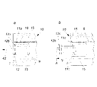
In the embodiment example represented in Figures 16a and 16b, an embodiment
example of a
bearing unit according to the invention is shown, in this case on the left-
hand side of a
schematically indicated roll 10, consisting of a wound material web 15. The
bearing unit itself has
an axial support, which can be pushed, for example, into a cardboard core 9 of
the roll 10. Small
limit stops 11c, which are formed by a radially protruding flange, prevent the
axial support, formed
the end cap 18, from being pushed too far into the roll 10.
Fig. 16a shows the defined inner end position I, in which the head 12b of the
bearing journal 12
still protrudes beyond the end face of the roll 10 (wound material web 15).
This inner end position
is defined by flange-like stops 12a and counter-stops 11a. In other words, due
to these stops 12a
and 11a, the bearing journal 12 cannot be pushed further inwards. However, to
implement the
axial coding according to the invention, it can be pushed outwards following
the direction of the
Date Recue/Date Received 2020-06-09
CA 03085169 2020-06-09
18
arrow 42, namely by the amount v in order to reach the outer end position A,
which is shown in
Fig. 16b. This outer end position is in turn also defined by similar stops and
counter-stops.
The invention relates not only to a refill, but also to a bearing unit for
such a refill, wherein the
bearing unit has an axial support, which can be inserted into a material web
15 wound to form a
roll 10 and is mounted axially displaceable with respect to the at least one
bearing journal. By
way of example, these bearing units are shown on the right in Figs. 13a to 15c
and can also be
sold separately without a material web 15 which is wound to form a roll 10.
Figs. 17a and 17b show an alternative embodiment of a bearing unit according
to the invention,
in which the bearing journal 12 surrounds the axial support instead of being
pushed into it, as
shown in the embodiment example according to Figs. 16a and 16b. Fig. 17a shows
the inner end
position, Fig. 17b the outer end position. The two end positions are defined
by stops and counter-
stops.
In the embodiment examples shown in Figures 18a and 18b, the inner and outer
end positions,
which are defined by stops and counter-stops, are shown again. A spring 17 is
provided.
According to Figure 18b, this spring 17 always attempts to push the bearing
journal 12 into the
outer end position A. To move the bearing journal 12, a testing device
provided in a dispenser
.. then only needs to apply force in one direction, namely from the outer end
position to the inner
end position. The spring 17 does this in the other direction. Simpler testing
devices acting "one-
dimensionally" in terms of force are thus possible.
Figures 19a and 19b show two further embodiment examples which are formed
similarly to the
end caps according to Figs. 16a and 16b. Only the mounting and the stops and
counter-stops for
defining the outer and inner end positions are slightly different
structurally.
In the embodiment examples of a refill according to the invention or bearing
unit according to the
invention represented in Figs. 20a to 20c, starting from a construction
similar to that of Figs. 16a
.. and 16b, there is a traversable inner counter-stop lib which defines the
inner end position I, as
shown by Fig. 20b. Since counter-stop 11b, which consists for example of a
small, traversable ¨
optionally resilient ¨ hump, can be traversed in its entirety, it can fulfil
two functions. Firstly it can
set the defined inner end position I (Fig. 20b) and secondly, due to its
traversability, it can also
allow the bearing journal 12 to travel even further into the roll 10 or into
the axial support located
therein, as shown by Fig. 20c. This is then the transportation position T, in
which tightly packed
storage of refills, for example in an outer box, is possible. However, despite
this possibility of
Date Recue/Date Received 2020-06-09
CA 03085169 2020-06-09
19
being pushed into the transportation position T, an inner end position is
still set in a defined
manner ¨ as shown in Fig. 20b.
In many embodiment examples shown, in particular in those according to Figures
13a to 20c, the
bearing journal 12 is mounted in a displaceable manner on (Fig. 17a, Fig. 17b)
or in (the other
aforesaid figures) the axial support and preferably has a smaller diameter
than the axial support.
As a result, the axial support can be held in the wound material web clamped
radially outwards,
whilst the bearing journal 12 can be moved axially further radially inwards.
It is also possible for the axial support and the axially displaceable bearing
journal to lie
substantially one behind the other ¨ when viewed in the axial direction ¨ as
is the case, for
example, in Figs. 25, 26, 27 and 30, yet to be described in more detail.
It is clear from the previously described embodiment examples that the bearing
journal 12
advantageously has a ¨ preferably cylindrical ¨ neck 12c and a head 12b having
a larger diameter
than the neck 12c.
By means of this construction, a mechanical testing device, for example in the
form of a curved
mechanical track, as shown by Figs. 5 to 8, can move the bearing journal in
the axial direction,
namely can pull it out of the refill, i.e. move it from the inner to the outer
end position, but also act
on it in the opposite direction. Pulling out is possible due to engagement
behind the head 12b in
the region of the neck 12c.
A good mounting and possibility of movement of the bearing journal in a guide
track are possible
if the end face of the bearing journal is formed by the top surface of the
head 12b running
substantially perpendicular to the longitudinal axis.
For the basic functioning of the invention, all that is necessary is for one
of the two bearing journals
to be formed according to the invention in an axially displaceable manner.
However, embodiment
examples in which both bearing journals are axially displaceable are also
conceivable and
possible. This is the case in the embodiment example represented in Fig. 10,
for example. Here,
the left-hand bearing journal 13 and the right-hand bearing journal 13 are
axially displaceable with
respect to the axial support designed as a support bar 11. There, the left-
hand bearing journal 13
is acted on by a spring 17 or in general by an energy storage mechanism.
Instead of mechanical
springs 17, rubber-elastic units (Fig. 26), magnets (Fig. 27) or fluid-filled
piston-cylinder units (Fig.
28) also come into consideration as energy storage mechanisms.
Date Recue/Date Received 2020-06-09
CA 03085169 2020-06-09
These figures will be described in more detail below:
The invention relates not only to a refill and to a bearing unit for such a
refill, but also to a
dispenser. This has already been explained at the outset with reference to
Figures 1 to 12. A
5 variant of the invention provides a dispenser for portions of a refill
with a material web wound to
form a roll, wherein the refill has at least one bearing journal, which can be
guided in a guide track
of the dispenser from an insertion position into a dispensing position,
wherein the refill is rotatably
mounted when in the dispensing position. The dispenser has a testing device
for verifying the
axial displaceability of the bearing journal with respect to the roll of the
refill, wherein the
10 dispensing of portions of the material web is released or blocked
depending on the axial
displaceability of the bearing journal. In the dispensers represented in Figs.
1 to 12, the testing
device according to the invention is mechanically implemented substantially by
an axially offset
(curved) portion of the guide track. In this portion, the testing device
attempts to move the bearing
journal 12 axially and to then release or block the dispensing of the material
web 15 depending
15 on the axial displaceability. This releasing or blocking or making
inoperative can occur as the
material web wound to form a roll (refill), which is inserted into the
dispenser from above, travels
downwards into the actual dispensing position, with the result that the
testing occurs before the
dispensing position, in which the roll then rotates to dispense the paper, is
reached. However, it
is also possible for the testing to be carried out in the dispensing position,
as represented
20 schematically by Figs. 21a and 21b by way of example. Here, a "normal"
support bar 11 (axial
support), i.e. one not formed according to the invention, is provided. This
has a bearing journal
12 which is not axially displaceable with respect to the support bar 11, but
rather is rigidly secured
thereto. It has a head 12b. In the dispensing position in Figs. 21a and 21b,
when the material web
15 is pulled downwards and the roll 10 thus rotates clockwise (21a), the
testing device, denoted
by 27 as a whole, now constantly attempts to move the axial journal axially.
For this purpose, the
testing device comprises a friction roller 27a, which abuts the material web
15 and is set in rotation
by this in the case of pulling. As shown in Fig. 21c, this friction roller 27a
has a curved hump 28
on its end face. This curved hump collides with the testing lever 29, which,
as shown in Fig. 21b,
is mounted displaceably in bearings 30 and is acted on to the left by a spring
31. If the hump 28
collides with the testing lever 29 during rotation, it pushes this to the
right. The fork-shaped end
29a, which surrounds the bearing journal 12, then pulls the latter to the
right by engaging behind
the head 12b. If a "normal" support bar 11 or axial support is now used, when
it is pulled to the
right, the left-hand bearing journal 13 falls out of a hold of the dispensing
position and the entire
roll 10 or refill is then no longer correctly mounted and dispensing is
prevented. If, however, the
right-hand bearing journal 12 can be axially displaced with respect to the
inserted support bar 11,
as provided according to the invention, the bearing journal 12 can oscillate
during the pulling
movement, without the support bar 11 and the left-hand bearing journal 13
which is connected
Date Recue/Date Received 2020-06-09
CA 03085169 2020-06-09
21
thereto in one piece, falling from their mounting. Such a refill or such a
bearing unit with an axially
displaceable right-hand bearing journal then passes the axial test.
Fig. 22 shows a testing device 27 for a roll 10 located in the dispensing
position, with a material
web 15 wound around a support bar 11. The right-hand bearing journal 12 is
formed axially
displaceable. The testing device comprises a testing magnet 37, which
interacts with a testing
magnet 38 on the outer end of the axially displaceable bearing journal 12. The
testing magnet 37
attempts to move the bearing journal 12 to the right in Fig. 22. If this is
successful due to its axial
displaceability, it enters the photoelectric sensor 39 and the electronic
evaluator releases the
catch 41, represented schematically, with the result that the material web can
be dispensed. If
the bearing journal 12 is not axially displaceable, the photoelectric sensor
37 does not respond
and the evaluator 40 blocks dispensing by means of the catch 41. Here,
therefore, the axial
displaceability can be electromechanically verified as a whole in the
dispensing position with the
testing device 27.
Fig. 23 shows an embodiment example of a refill or roll 10 according to the
invention with an axial
support designed in the form of a support bar 11, in which the right-hand
bearing journal 12 is
axially displaceable whilst the left-hand bearing journal 13 is formed in one
piece with the support
bar 11. In this embodiment, there is a defined inner end position I, in which
the bearing journal 12
still protrudes beyond the refill. This is defined in that the bearing
journal, formed having a T-
shaped cross section, abuts the inner end at the bottom of a blind hole in the
support bar 11.
Starting from this inner end position, the bearing journal 12 can then be
pulled outwards, wherein
in principle no defined outer end position must be provided to implement the
proper functioning
of the invention. In the embodiment example represented in Fig. 23, the
bearing journal 12 is
namely loosely inserted, and can be completely separated from the support bar
11 when it is
pulled out to the right in the direction of the two arrows. Of course,
measures can be taken to
prevent the bearing journal 12 from falling out of the support bar 11 during
transportation.
The embodiment example represented in Fig. 24 is a particularly preferred
embodiment with an
axial support or support bar 11 which has laterally projecting protrusions 24,
which provide a good
retention in a material web wound to form a roll. The left-hand bearing
journal is formed as one
piece with the support bar 11 whilst the right-hand bearing journal 12 is
axially displaceable
according to the invention, namely by the displacement amount v, wherein the
inner and outer
end positions are defined and set by stops and counter-stops, not described in
more detail here.
The right-hand bearing journal 12 is also rotatable in the axis of rotation or
roll axis 14 and on the
Date Recue/Date Received 2020-06-09
CA 03085169 2020-06-09
22
end face has a groove 19 or generally a non-rotational surface. With such a
bearing journal, a
rotary coding and an axial coding can be achieved.
In the embodiment example represented in Fig. 25, the right-hand bearing
journal 12 is arranged
in a line with the actual support bar 11 or axial support together with the
left-hand bearing journal
13, thus one behind the other when viewed in the axial direction. In between,
an energy storage
mechanism in the form of a compression spring 17 acts.
The inner end position, which is shown in Fig. 25, is defined by the inner end
of the bearing journal
.. 12 abutting the right-hand end of the support bar 11. Similarly to the
embodiment example
according to Fig. 23, there is no outer defined end position here.
Fig. 26 is formed similarly. Here, however, the energy storage mechanism
consists substantially
of a rubber-elastic unit 32 which is fully compressed in Fig. 26 and thus sets
the inner end position.
Starting from this inner end position, the bearing journal 12 can be moved
outwards to the right
in the direction of the arrow, wherein the rubber-elastic unit 32 is
stretched.
In the embodiment example represented in Fig. 27, the right-hand bearing
journal 12 is axially
displaceable with respect to the axial support or support bar 11 and in part
itself also functions as
an axial support. The two parts 16a and 16b are arranged one behind the other
in the axial
direction. Between the two parts magnets act in the repelling direction and
thus form an energy
storage mechanism which attempts to push the two parts 16a and 16b apart.
A similar function is implemented in the embodiment according to Fig. 28.
Here, a piston-cylinder
.. unit 34 acts as an energy storage mechanism between the two parts 16a and
16b, wherein the
cylinder is filled with a gaseous compressible fluid 35. A seal is denoted by
36. Here too, the
piston-cylinder unit 34 acts as an energy storage mechanism which pushes the
two parts 16a and
16b apart. In all the embodiment examples according to Figs. 25t0 28, any
testing device present
needs to exert a force axially inwards only in one direction. The energy
storage mechanism, which
is implemented in many different forms (springs 17, rubber-elastic units 32,
magnets 33 or piston-
cylinder units 34) then acts in the other direction.
Fig. 29 shows a one-piece embodiment in which the spring 17 is formed in one
piece with the
support bar 11 or the right-hand bearing journal 12.
Fig. 30 schematically shows a simple embodiment example of a bearing unit
according to the
invention with two components 16a and 16b arranged one behind the other in the
axial direction,
Date Recue/Date Received 2020-06-09
CA 03085169 2020-06-09
23
wherein the left-hand component has protrusions 24 and acts as an axial
support in a refill. The
right-hand part 16b is simultaneously an axial support and, at its right-hand
end, a bearing journal
12. The inner defined end position is reached by the two parts 11 and 12
abutting one another.
For reasons of clarity, Fig. 30 still shows a small gap between the two parts,
but this disappears
when the inner end position is reached.
In the embodiment of a refill according to the invention according to Fig. 31,
two parts 16a and
16b lying one behind the other when viewed in the axial direction are likewise
provided, but these
are additionally interconnected in an axial tongue-and-groove connection to
increase stability.
In the embodiment example represented in Fig. 32 of a refill according to the
invention, the
bearing journal 12, which is mounted axially displaceable in the support bar
11 or axial support,
does not have a separate head. Here, the testing device must be designed
differently from Figs.
1 to 11. For example, the testing device can attempt to move the bearing
journal 12 axially by
means of frictional locking. Depending on the test result, a release or
blocking of dispensing in
the sense of an axial coding can then be effected by means of a suitable
mechanical or electronic
control. Fig. 32 shows that, although the head 12b able to be engaged from
behind is preferred,
it is in principle not required for the functionality.
In the embodiment examples shown in Figs. 33 and 34, a rubber-elastic element
is used again to
produce the axial displaceability of the bearing journal 12, more precisely of
its head 12b. In the
embodiment example represented in Fig. 33, the head 12b is formed of a
relatively hard material
and only the neck 12c is formed of rubber-elastic material (including the T-
shaped anchoring
protruding on both sides in the parts 11 and 12b). In the embodiment example
represented in Fig.
34, the head 12b itself is also made of rubber-elastic material.
Date Recue/Date Received 2020-06-09
CA 03085169 2020-06-09
24
List of reference numbers
1 dispenser
2 cover
3 walls
4 guide track
5 axially offset portion
6 insertion position
7 dispensing position
8 collection chamber
9 cardboard core
10 roll / refill
11 support bar
11a counter-stop
llb traversable inner counter-stop
11c limit stops
12 bearing journal
12a stop
12b head able to be engaged from behind
12c neck
13 bearing journal
14 roll axis
15 material web
16a,b axially displaceable parts of the support bar
17 spring
18 end cap
19 (radial) groove
20 ridge
21 ridges
22 collar
23 claw
24 protrusions
25 unwinding arrow
26 small arrow
27 testing device
27a friction roller
28 hump
Date Recue/Date Received 2020-06-09
CA 03085169 2020-06-09
29 testing lever
29a (fork-shaped) end
bearing
31 spring
5 32 rubber-elastic unit
33 magnets
34 piston-cylinder unit
fluid
36 seal
10 37 testing magnet
38 magnet
39 photoelectric sensor
evaluator
41 catch
15 42 arrow
43 retaining tip
nAte Recue/Date Received 2020-06-09