Note: Descriptions are shown in the official language in which they were submitted.
CA 03085364 2020-06-10
WO 2019/139765
PCT/US2018/066827
FIELD OF THE INVENTION
[0001] This invention relates to railway ties. In particular, this invention
relates to
railway ties having a keyway below an overlying rail to constrain lateral and
longitudinal
movement of the rail. The invention also provides a means to attach the rail
plate and pad to
the tie in which the attachment means is protected from damage. The invention
also provides
an inspection mechanism for determination of whether the assembly is properly
secured to the
tie.
BACKGROUND OF THE INVENTION
[0002] As a train runs along a set of rails, it applies lateral forces to the
rails, pushing
them outward at the point where they are fastened to the supporting ties. It
is obviously
desirable to minimize the effect of these lateral forces, as any excessive
movement of the rail
will move the rails heads apart, widening the gauge of the track and allowing
the train wheels
- 1 -
CA 03085364 2020-06-10
WO 2019/139765
PCT/US2018/066827
to slip off the inside of the rail, causing a derailment. Of equal concern is
the longitudinal
force applied to the rail as the train runs along the rails and due to
temperature changes. This
force tends to push or pull the rail, and the rail plate holding it to the
rail, off the edge of the
tie, leaving that portion of the rail unsupported and weak, or disrupting the
rail anchoring to
the tie to resist thermal longitudinal force, again leading to the possibility
of a derailment.
[0003] It is known to minimize the effects of the train's forces by securing
the rails
and ties against movement. For example, U.S. Patent No. 9758932 to Lu et al.
describes a
ballastless track system wherein concrete slabs carrying the rails are
provided with a
depending structure on its underside that interacts with the underlying base
to try to restrain
movement of the entire slab and the overlying rails. However, such systems do
not restrict the
movement of the rails themselves, apart from the entire assembly as a whole.
This may be
less efficient and effective.
[0004] More typically, movement of a rail supported on a tie is directly
restricted by
holding it down on a rail plate, which usually includes a rail seat to
accommodate the base of
the rail. The rail or rail plate is in turn secured to the tie by fasteners.
The fasteners are
generally exposed on the tie, which can simplify the inspection, repair and/or
replacement of
the fasteners as needed. However, in a derailment, these fasteners are
vulnerable to damage
when one or more train wheels forcefully impacts the area beside the rail.
This can
significantly delay repair after a derailment, and the return of the rail to
full availability.
Simply covering the fasteners can make it very difficult to inspect the
assembly throughout its
lifetime, in order to confirm that it properly secures the rail or rail plate.
If the assembly is not
secured or loosens over time, a catastrophic separation of the rail from the
tie may occur.
- 2 -
CA 03085364 2020-06-10
WO 2019/139765
PCT/US2018/066827
[0005] U.S. Patent No. 2276799 to Spencer and U.S. Patent No. 715698 to Saleme
both provide ties having shaped keyways in their upper surfaces, in order to
interlock with
components passing over the tie. Saleme discloses a longitudinal passageway
through which a
rail base is fed. Spencer discloses a lateral passageway, either in a rail
plate or in the tie
surface, into which a projection on the underside of the rail is fitted and
slides horizontally to
interlock with the tie or rail plate. The configuration of the rail and the
keyed surface are both
relatively complex and would not seem to provide the expected lateral support
to a rail.
[0006] GB Patent No. 1169715 to Waters discloses a rail for which additional
lateral
support is provided by using a rail with a depending rib that is located in a
linear recess
extending across the tie, with a resilient pad between the rail and the tie.
In another
embodiment, Waters provides a standard rail, and a resilient pad having a
depending rib that
fits into the recess. However, the first embodiment is likely susceptible to
abrasion and
deterioration between the rail base and the tie, as there is no plate between
them. In the
second embodiment, having the resilient pad seems to provide less additional
lateral support to
the rail than would a stiffer or stronger piece, such as the rail base or a
rail plate.
[0007] U.S. Patent No. 2242773 to Boyce discloses a tie plate with a pair of
ribs on
an under surface that are embedded in a tie. These are located towards the
outer edge of the
plate, just outside the rail base. U.S. Patent No. 4108378 to Raymond
discloses a rail plate
having depending ribs, and a tie having a recess with grooves running across
the width of the
tie. The rail plate fits into the recess while its depending ribs fit into the
grooves, thereby
anchoring the plate to the tie and preventing lateral movement. Connection of
the tie plate to
the tie is provided by wood screws, while spikes secure the rail to the plate.
In both of these
patents, the depending rib provides additional lateral support to the plate,
preventing it from
- 3 -
CA 03085364 2020-06-10
WO 2019/139765
PCT/US2018/066827
moving sideways on the tie when a train passes. However, the linear shape and
straight
orientation of the ribs and grooves relative to the tie does not do anything
to restrict
longitudinal movement of the rail plate on the tie.
[0008] U.S. Patent No. 3957201 to Johnson shows a concrete tie having an
anchor
structure set into a recess and a rail seat formed by base plate. A rail plate
pad is located
between the anchor and the rail. A threaded stud is attached to the underside
of plate,
preferably by spot welding, presumably to anchor the anchor structure into the
body of the
concrete tie. The threaded stud is permanently attached (welding being the
preferred method)
and evidently intended to be completely embedded and not accessible for
repairs or
replacement.
[0009] . U. S . Patent No. 4925094 to Buekett similarly discloses a concrete
tie with a
cast-in rail plate defining a rail seat, with downwardly projecting lugs
embedded in the tie
body. The lugs are provided to ensure a mechanical connection between the
plate and the tie.
Again, due to the nature of the tie and the connection with the lugs, removal
of the rail plate
for replacement or repair is not feasible.
[0010] U.S. Patent No. 8625878 to Haas et al. describes an inspection system
for a
railway track that uses vision technology to read and compare a configuration
of rail
components with safety requirements stored in an associated processor.
Similarly, U.S. Patent
No. 9441956 to Kainer et al. discloses a tie inspection system that uses a
generated light to
produce an image of the tie in order to compare it with stored parameters.
U.S. Pub. No.
2012/0192756 to Miller et al. discloses a vision-based inspection system
mounted on a railcar
or other vehicle. However, all of these systems are relatively complex and
require computer
- 4 -
CA 03085364 2020-06-10
WO 2019/139765
PCT/US2018/066827
processing resources, along with the associated time and cost limitations. A
visual inspection
to ensure that the rail components are in place is a simpler and less
expensive alternative.
[0011] It is therefore an object of this invention to provide a tie and a rail
fastening
assembly that overcomes the foregoing deficiencies.
[0012] It is a further object of the invention to provide a fastening system
that does
not require traditional insulators between the rail and clip, yet still
provides rail-to-rail
electrical isolation.
[0013] It is further an object of the invention to provide a system wherein
lateral and
longitudinal forces of passing trains are transmitted from the rail into the
tie, not into the plate-
to-tie fastening system. Although concrete ties historically do not use rail
plates between the
rail and the tie, the use of a plate will significantly reduce or even
eliminate rail seat
deterioration as it reduces the stresses that pass from the rail base into the
concrete. Using a
rail plate significantly increases the contact area (plate to concrete tie) as
compared to the
contact area of a rail base directly on the concrete tie, thus helping to
spread the forces from
the rail plate over a larger area of the tie and therefore reducing or
eliminating abrasion of the
concrete.
[0014] It is a further object of the invention to provide a system in which
alternate
fastening systems may be employed simply by changing the rail plate, rather
than the tie.
[0015] It is a further object of the invention to provide a plate-to-tie
fastening system
that requires only a minor amount of clamping or connecting force; however, if
a fastener is
used, a single fastener may be all that is required to provide the needed
force to retain the tie
plate on the tie. Additional means may be used to prevent loosening of the
fastener.
- 5 -
CA 03085364 2020-06-10
WO 2019/139765
PCT/US2018/066827
[0016] It is a further object of the invention to provide a fastening system
located to
protect it from damage, for example during a derailment.
[0017] It is a further object of the invention to provide a rail plate and
rail pad that
facilitate inspection of the assembly in place on a tie, when used together.
[0018] It is yet a further object of the invention to provide a mechanism to
allow easy
verification of whether the fastening system is properly retaining the plate
and rail on the tie.
[0019] These and other objects of the invention will be better understood by
reference to the detailed description of the preferred embodiment which
follows. Note that the
objects referred to above are statements of what motivated the invention
rather than promises.
Not all of the objects are necessarily met by all embodiments of the invention
described below
or by the invention defined by each of the claims.
SUMMARY OF THE INVENTION
[0020] The invention comprises a fastening system, to hold rails down on a
concrete
tie. A keyway, which preferably has a non-linear shape, is provided under each
rail, across the
width of the tie. The keyway is preferably narrower than the width of the rail
base and
accommodates a rail plate, which has a lower surface comprising a depending
portion shaped
to fit into the keyway in the tie, thus holding the rail plate and rail in
place on the tie, while
transmitting lateral and longitudinal forces from a passing train down into
the tie, rather than
into the rail and rail base alone. The bulk of the rail plate does not fit
into the keyway, instead
having an upper surface comprising a recess bounded by a pair of shoulders
shaped to hold the
rail base and to support a pair of rail clips that will hold the rail to the
rail plate. Neither the
rail clips nor the rail shoulders are therefore in direct contact with the
tie.
- 6 -
CA 03085364 2020-06-10
WO 2019/139765
PCT/US2018/066827
[0021] A rail plate pad is provided between the rail plate and the tie
surface, lining
the inner surfaces of the keyway as well as the upper surface of the tie
underneath the rail
plate, to protect the tie from abrasion, to dissipate loads and to provide
shock absorption. The
pad thickness, hardness, internal geometry (shape factor) and other properties
may be selected
to provide desired track deflection, vertically and laterally, without the
need to adjust the tie
recess, tie size or other components of the assembly.
[0022] Due to the shape of the keyway, it is possible to simply place the rail
plate
pad and rail plate within the keyway and omit attachment means, while still
sufficiently
restraining lateral and longitudinal movement of the tie plate on the tie. As
this may allow
separation of the tie from the plate, an alternative embodiment includes one
or more bolt holes
within the keyway to accommodate bolts that pass from the rail plate and
through the rail plate
pad into the tie. The bolt heads may be covered or capped for security and to
prevent them
from contacting the underside of the rail base. The bolt cover may be keyed,
to prevent or
minimize loosening of the bolt. The bolt cover may cover the heads of
individual fasteners, or
may cover most or all of the rail seat. A gauge adjusting mechanism may be
provided as part
of the bolt cap. The positioning of the bolts under the rail provides an
extremely protected
area in which the bolts will not be damaged in case of a derailment, which can
simplify
recovery efforts, making it faster and easier to get a section of track back
into operation after a
derailment.
[0023] In another embodiment, similar protection against derailment damage may
be
provided for attachment means located on top of the tie plate and outside of
the rail base.
[0024] In another aspect of the invention, the rail plate and the rail plate
pad may be
provided with an inspection mechanism, which allows an observer to quickly
determine
- 7 -
CA 03085364 2020-06-10
WO 2019/139765
PCT/US2018/066827
whether the fasteners are sufficiently retaining the rail plate in the correct
position on the
upper surface of the tie.
[0025] In one aspect, the invention comprises a railway tie having an upper
surface
to support a rail crossing a longitudinal axis of the tie, comprising at least
one keyway in the
upper surface wherein the keyway provides support to the rail to restrain the
rail from moving
along the longitudinal axis and transverse the longitudinal axis. The keyway
comprises at
least one edge or a plurality of edges, and the edge or at least one of the
edges is not
perpendicular to the longitudinal axis. The keyway may be shaped like an
hourglass.
[0026] In a further aspect, the railway tie may comprise a fastening assembly
to
secure the rail to the tie, the fastening assembly comprising a rail plate
having an upper
surface and an opposed lower surface; shoulders on the rail plate upper
surface to define a rail
seat therebetween, the rail seat being configured to accommodate a base of the
rail; and at
least one recess within the rail seat to accommodate a fastener configured to
secure the rail
plate to the tie. A cap may be provided, the cap configured to fit within the
recess; cover an
upper portion of the fastener; and sit at least partially co-planar with or
below the rail seat.
The cap may itself comprise a recess to accommodate the upper portion of the
fastener. The
cap recess may be non-circular.
[0027] In a further aspect, the rail plate may comprise a protrusion on the
lower
surface, the protrusion being shaped and sized to fit within the keyway.
[0028] In yet a further aspect, the assembly may be provided with a rail pad
configured to rest between the lower surface of the rail plate and the keyway.
[0029] In yet a further aspect, the assembly may be provided with a rail plate
pad
configured to rest between the rail seat and the rail. An underside of the
rail plate pad may
- 8 -
CA 03085364 2020-06-10
WO 2019/139765
PCT/US2018/066827
comprise at least one protrusion configured to fit within the recess and to
cover an upper
portion of the fastener. The protrusion may comprise a recess to accommodate
the upper
portion of the fastener. The protrusion recess may be non-circular.
[0030] In yet a further aspect, the railway tie may further comprise an
inspection
apparatus to indicate whether the rail plate is secured to the railway tie,
the apparatus
comprising at least one protrusion on an upper surface of the tie; and at
least one aperture on
the rail plate, the aperture being aligned with the protrusion such that
alignment of the rail
plate and the keyway allows the protrusion to extend through the rail plate
aperture and be
visible above the upper surface of the rail plate; wherein misalignment of the
rail plate and the
keyway will result in the protrusion receding from the rail plate aperture.
The protrusion may
be cast as part of the upper surface of the tie, or may be anchored into the
upper surface of the
tie. In a further aspect, the inspection mechanism may comprise an elongated
pin configured
to fit through an eye in the protrusion and to extend at least partially
across the tie; the pin
being further configured to break when the misalignment causes the protrusion
to recede from
the aperture; and the pin comprising at least one extension configured to be
visible in a first
position outside the rail plate when the pin is intact, and being further
configured to move to a
second position when the pin breaks. The protrusion and the aperture may be
located within a
recess in the rail plate. The recess may be located under a rail seat of the
rail plate.
[0031] In another aspect, the invention may comprise a fastening assembly for
a
railway tie to secure a rail to the tie, the fastening assembly comprising a
rail plate having an
upper surface and an opposed lower surface; shoulders on the rail plate upper
surface to define
a rail seat therebetween, the rail seat being configured to accommodate a base
of the rail and
the shoulders being configured to accommodate rail fasteners to hold the rail
in the rail seat; at
- 9 -
CA 03085364 2020-06-10
WO 2019/139765
PCT/US2018/066827
least one recess within the rail plate, either within the rail seat or
elsewhere on the rail plate, to
accommodate a fastener configured to secure the rail plate to the tie; and a
cover configured to
overlay an upper portion of the fastener.
[0032] In a further aspect, the cover may comprise a cap configured to fit
within the
recess and to sit at least partially co-planar with or below the upper surface
of the rail plate.
The cap may comprise a recess to accommodate the upper portion of the
fastener. The cap
recess may be non-circular. Instead or in addition, the recess and the cap may
be non-circular.
[0033] In a further aspect, the cover may comprise at least one protrusion
from an
underside of a rail plate pad configured to rest between the rail seat and the
rail. The
protrusion may comprise a recess to accommodate the upper portion of the
fastener. The
recess in the rail plate pad protrusion may be non-circular.
[0034] In yet a further aspect, the cover may comprise a cap configured to fit
within
the recess and to sit at least partially co-planar with or below the upper
surface of the rail seat.
The cap may comprise a recess to accommodate the upper portion of the
fastener. The cap
recess may be non-circular. Instead or in addition, the recess and the cap may
be non-circular.
[0035] In yet a further aspect, the assembly may be provided with a rail pad
configured to rest between the lower surface of the rail plate and the keyway.
[0036] In yet a further aspect, the assembly may be provided with a rail plate
pad
configured to rest between the rail seat and the rail.
[0037] In yet a further aspect, the assembly may be provided with an
inspection
apparatus to indicate whether the rail plate is secured to the railway tie,
the apparatus
comprising: at least one protrusion on an upper surface of the tie; and at
least one aperture on
the rail plate, the aperture being aligned with the protrusion such that
installation of the rail
- 10 -
CA 03085364 2020-06-10
WO 2019/139765
PCT/US2018/066827
plate on the tie allows the protrusion to extend through the rail plate
aperture and be visible
above the upper surface of the rail plate; wherein misalignment the rail plate
on the tie will
result in the protrusion receding from the rail plate aperture. The protrusion
may be cast as
part of the upper surface of the tie, or may be anchored into the upper
surface of the tie. The
inspection mechanism may further comprise an elongated pin configured to fit
through an eye
in the protrusion and to extend at least partially across the tie; the pin
being further configured
to break when the misalignment causes the protrusion to recede from the
aperture; and the pin
comprising at least one extension configured to be visible in a first position
outside the rail
plate when the pin is intact, and being further configured to move to a second
position when
the pin breaks. The protrusion and the aperture may be located within a recess
in the rail
plate. The recess may be located under a rail seat of the rail plate.
[0038] In a further aspect, the rail plate may comprise a protrusion on the
lower
surface, the protrusion being shaped and sized to fit within a keyway on an
upper surface of
the tie.
[0039] In another aspect, the invention comprises an inspection apparatus to
indicate
whether a rail plate is secured to a railway tie, the apparatus comprising at
least one aperture
on the rail plate, the aperture being aligned with the protrusion such that
installation of the rail
plate and the rail plate pad on the tie allows the protrusion to extend
through the aperture and
be visible above an upper surface of the rail plate; wherein misalignment of
the rail plate and
the tie will result in the protrusion receding from the aperture. The
protrusion may be cast as
part of the upper surface of the tie, or may be anchored into the upper
surface of the tie. The
inspection apparatus may further comprise a rail plate pad configured to fit
between the rail
- 11 -
CA 03085364 2020-06-10
WO 2019/139765
PCT/US2018/066827
plate and the tie. The rail plate pad may further comprise at least one
aperture aligned with the
rail plate aperture and adapted to accommodate the tie protrusion.
[0040] In a further aspect, the inspection mechanism may further comprise an
elongated pin configured to fit through an eye in the at least one protrusion
and to extend at
least partially across the tie; the pin being further configured to break when
the misalignment
causes the protrusion to recede from the aperture; and the pin comprising at
least one
extension configured to be visible in a first position outside the rail plate
when the pin is
intact, and being further configured to move to a second position when the pin
breaks. The
protrusion and the aperture may be located within a recess in the rail plate.
The recess may be
located under a rail seat of the rail plate.
[0041] The foregoing may cover only some of the aspects of the invention.
Other
aspects of the invention may be appreciated by reference to the following
description of at
least one preferred mode for carrying out the invention in terms of one or
more examples. The
following mode(s) for carrying out the invention is not a definition of the
invention itself, but
is only an example that embodies the inventive features of the invention.
BRIEF DESCRIPTION OF THE DRAWINGS
[0042] At least one mode for carrying out the invention in terms of one or
more
examples will be described by reference to the drawings thereof in which:
[0043] Fig. 1 is a perspective view of a railway tie having the keyway and a
first
embodiment of the rail fastening assembly of the invention;
[0044] Fig. 2 is a side view of the keyway and rail fastening assembly of Fig.
1;
- 12 -
CA 03085364 2020-06-10
WO 2019/139765
PCT/US2018/066827
[0045] Fig. 3 is an exploded view of the keyway and rail fastening assembly of
Fig.
1;
[0046] Fig. 4 is a perspective view of a railway tie having the keyway and a
second
embodiment of the rail fastening assembly of the invention;
[0047] Fig. 5 is a side view of the keyway and rail fastening assembly of Fig.
4;
[0048] Fig. 6 is an exploded view of the keyway and rail fastening assembly of
Fig.
4;
[0049] Fig. 7 is a perspective view of a part of a railway tie having the
keyway and a
third embodiment of the rail fastening assembly of the invention;
[0050] Fig. 8 is a perspective view of a first embodiment of an inspection
mechanism
of the invention;
[0051] Fig. 9 is a side view of the inspection mechanism of Fig. 8;
[0052] Fig. 10 is a side view of a second embodiment of an inspection
mechanism of
the invention; and
[0053] Fig. 11 is an interior view of the inspection mechanism of Fig. 10.
DETAILED DESCRIPTION OF AT LEAST ONE MODE FOR CARRYING OUT THE INVENTION IN
TERMS OF EXAMPLE(S)
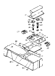
[0054] As best seen in Fig. 1, a typical tie 10 is an elongated body with an
upper
surface 26 which is crossed by a pair of rails 12. A rail plate 14 may be
provided under the
rail 12 for support and stability, and to reduce contact pressures on the
upper surface 26 of the
tie 10, to reduce or eliminate rail seat deterioration. The rail plate 14 may
be fastened to the
tie 10 by any suitable, preferably removable, fasteners; several plate
fasteners are known and
may be used, such as bolts with threaded inserts, snap connections, cables,
cast threaded studs,
- 13 -
CA 03085364 2020-06-10
WO 2019/139765
PCT/US2018/066827
and twist locks, among others. The plate fasteners may be mounted directly on
the upper
surface 26 of the tie 10, outside of the rail plate 14, as long as they apply
sufficient force to
hold the rail plate 14 to the tie 10.
[0055] The rail plate 14 comprises a rail seat 16 to accommodate the base of
rail 12.
The rail plate is defined by shoulders 18, which retain rail fasteners, such
as clips 20, to hold
the base of the rail 12 to the rail plate 14. Shoulders 18 also serve to
provide a bearing surface
for the edge of rail to bear against, thereby providing gauge restraint. It
will be evident that
the rail plate 14 carries the means to retain the rail fasteners, avoiding the
need to use concrete
ties having cast-in shoulders or other inserts, along with specific rail
fasteners to match those
inserts. The invention therefore provides flexibility, as the type of fastener
used can be
changed simply by using a different rail plate 14, which can therefore
accommodate different
rail sizes. Essentially, the tie is "generic", instead of being restricted to
the particular type of
elastic clip associated with the clip-receiving shoulders or inserts that are
cast into the tie. If it
is desired to use a different elastic clip, it is possible to merely change
out the plates to obtain
clip receiving systems compatible with the new preferred clips, rather than
having to change
the entire tie. The shoulders 18 and associated rail fasteners illustrated are
exemplary; several
rail fasteners are known and may suitably be used, such as resilient clips
driven longitudinal to
the rail, resilient clips driven perpendicular to the rail, and resilient
clips tensioned via screws
or bolts. Production of the tie may also be simpler, as it can be made without
worrying about
proper insertion of various cast-in shoulders or other inserts for various
clip systems. In
addition, damaged clip retainers may be repaired or replaced simply by
replacing the plate,
rather than requiring an entirely new tie.
- 14 -
CA 03085364 2020-06-10
WO 2019/139765
PCT/US2018/066827
[0056] Cushioning means, such as rail plate pad 22 may be provided between the
rail
plate 14 and the tie 10. The thickness, hardness, geometry and other
properties of rail plate
pad 22 may be selected to provide desired track deflection, vertically and
laterally.
[0057] As best seen in Fig. 2, the lower surface of rail plate 14 is not
planar, as it
comprises a depending portion 28. The depending portion 28 is shaped to fit
within a keyway
24 in the upper surface 26 of tie 10. Rail plate pad 22 is similarly provided
with a lower
section 30 which is shaped to fit between the keyway 24 and the depending
portion 28. It can
be seen that the depending portion 28 is not necessarily co-extensive with the
base of the rail
12, nor is it necessarily directly underneath the base of rail 12, although
either or both may be
true in different embodiments. The use of a rail plate will significantly
reduce or even
eliminate rail seat deterioration as it reduces stresses from rail base into
the concrete. Further,
by providing a rail plate, the plate to concrete area is significantly greater
versus the typical
concrete tie rail base to concrete area, which helps to spread the forces from
the rail plate over
a larger area of the tie, therefore reducing or eliminating abrasion of the
concrete.
[0058] Referring now to Fig. 3, the keyway 24 is preferably a shape that is at
least
partially more than merely a single straight, linear shape, and has edges that
are at least
partially not perpendicular to the long edges 44 of the tie 10, which run
parallel to the
longitudinal axis of the tie 10. In the illustrated embodiment, the edges 46
of keyway 24 are
approximately in the shape of an hourglass, which comprises four edges 46a,
46b, 46c, 46d,
each of which are non-perpendicular relative to the edges 44 of the tie 12.
The angled edges
will provide both lateral support, i.e. along the axis of the tie 10, and
longitudinal support, i.e.
along the axis of the rail 12, helping to keep the rail plate 14 (and thus the
rail 12) from
moving laterally on the tie 10 as well as longitudinally relative to the tie
10. It will be
- 15 -
CA 03085364 2020-06-10
WO 2019/139765
PCT/US2018/066827
understood that the illustrated hourglass is an effective embodiment, but
other shapes having
at least one or more non-perpendicular or partially non-perpendicular edges
would also be
effective. Some exemplary keyway shapes that would also be effective include a
polygon,
including but not limited to a pentagon, a hexagon or an octagon, an X, a T,
an I, a V, a circle,
a diamond with angled or rounded edges, a cross or a plus sign. In any case,
the keyway 24,
and thus the tie 10, absorbs forces transmitted from passing trains, instead
of stressing the
fasteners holding the assembly to the tie. It will further be understood that
the keyway 24 may
extend completely across the width of the tie between long edges 44, as shown,
but need not
do so. More specifically, while it is preferred that the keyway 24 intersect
both edges 44,
which would be most efficient for draining water away from the rail, it will
be understood that
the keyway 24 may instead intersect one or neither of long edges 44.
[0059] . The shape of the keyway may therefore alone provide adequate support
to
sufficiently limit movement of the rail plate 14 and rail 12 relative to the
tie 10. It will be
understood that there is some resiliency offered by the plate pad 22 that will
allow plate lateral
and longitudinal deflection under load. This may allow a concrete tie to
behave in a manner
similar to wood or may simply offer more resiliency against vibration and also
to help
distribute the load amongst more ties. In the case of loss of under-tie
support, however,
additional security is provided to ensure the retention of rail plate 14 on
tie 10 through the use
of one or more removably secured plate-to-tie fasteners, such as bolts 34. In
the embodiment
shown in Fig. 3, the plate fasteners 34 are located in the rail seat 16, under
the base of the rail
12. One or more recesses 32 may be provided in rail seat 16, with
corresponding recesses 36
and 38 provided in rail plate pad 22 and in the tie 10, respectively, to
accommodate the plate
fasteners 34. Recesses 32 and 36 are preferably somewhat larger than the body
of plate
- 16 -
CA 03085364 2020-06-10
WO 2019/139765
PCT/US2018/066827
fastener 34, allowing some degree of movement of rail plate 14 and rail plate
pad 22 about the
body of plate fastener 34. This also helps to ensure that forces from passing
trains are
transmitted into the keyway 24 and the tie 10, rather than into the plate
fastener 34. Washers
40 may be provided to assist in securing the plate fasteners 34 through the
slightly enlarged
recesses.
[0060] It can be seen that in this embodiment, any fasteners 34 holding the
rail plate
14 and rail plate pad 22 in place on the tie 10 are substantially protected
from damage that
might be caused, for example, by a train wheel during a derailment. Further
protection of the
plate-to-tie fasteners 34 may be provided by one or more caps 42, which fit
over the top or
heads 48 of the plate fasteners 34. The recesses 32 are preferably sized to
allow the heads 48
of plate fasteners 34 to lie below the upper surface 50 of the rail seat 16,
such that the upper
surface 52 of caps 42 is either co-planar with the upper surface 50 or is
slightly recessed. This
arrangement allows the rail 12 to sit securely within rail seat 16 while still
protecting the heads
48 of plate fasteners 34. As can be seen in Fig. 3, recesses 32 and caps 42
may be any suitable
shape but are preferably non-circular, which will tend to reduce the
likelihood that the caps
will rotate or otherwise move under forces applied to the assembly by passing
trains. This in
turn helps to prevent the plate fasteners 34 from loosening under those
forces. In a further
aspect, cap 42 may be provided with a non-circular recess 54 on its underside;
the non-circular
recess 54, which may be hexagonal as an example, will interact with the head
48 of plate
fastener 34 to prevent it from turning and therefore loosening.
[0061] A second embodiment of the invention is shown in Figs. 4 ¨ 6. In this
and the
other embodiments to be described, the same reference numbers are used to
denote the same
parts as those in the embodiment shown in Figs. 1 ¨ 3.
- 17 -
CA 03085364 2020-06-10
WO 2019/139765
PCT/US2018/066827
[0062] In this embodiment, rail plate 14 is provided with shoulders 18 shaped
to
accommodate a different type of rail fastener, in this case an e-clip 120.
Again, this type of
shoulder and rail fastener are exemplary; because the plate is changeable, any
suitable rail
fasteners may be used, including those that can be driven in a direction
perpendicular to the
rail, longitudinal to the rail or using tension. Again, the rail fasteners may
instead be mounted
directly on the upper surface 26 of the tie 10, outside of the rail plate 14,
as long as they apply
sufficient force to hold the base of the rail 12 to the tie.
[0063] Fig. 6 illustrates another embodiment of means by which the plate-to-
tie
fasteners can be protected, in the form of a rail seat pad 56 that fits in
rail seat 16 between
shoulders 18. Rail seat pad 56 also cushions the contact between rail 12 and
rail plate 14. The
underside of rail seat pad 56 may be flat, such that it lies over bolt caps 42
(not shown) as
described with respect to the previous embodiment. Alternatively, the
underside of rail seat
pad 56 may be provided with one or more depending portions 58, shaped to fit
into the one or
more recesses 132 in rail seat 16 that hold the plate fastener 34 and recess
32. The depending
portions 58 may sit on top of cap 42 (not shown) if provided, or depending
portions 58 may be
provided with one or more recesses 60 to fit directly over the head 48 of one
or more plate
fasteners 34. Without separate bolt caps, this embodiment may be simpler and
less expensive
to install.
[0064] Rail seat pad 56 may have an upper surface 62 that is substantially
flat, or
may be provided with one or more raised edges 64. Edges 64 assist with
electrical insulation
between the rail 12 and the rail plate 14. Edges 64 may be provided in
different thicknesses,
allowing some amount of gauge adjustability, which can help simplify
installation of the rail
12 on the tie 10.
- 18 -
CA 03085364 2020-06-10
WO 2019/139765
PCT/US2018/066827
[0065] Instead of or in addition to providing one or more plate fasteners 34
located
under the rail seat, plate fasteners 34 may be located outside of the rail
seat 16, as shown in
Fig. 7. One or more recesses 72 are provided in rail plate 14 for plate
fasteners 34. The
recesses 72 are preferably sized to accommodate plate fasteners 34 such that
heads 48 lie
below the upper surface 66 of the rail plate 14. This provides some protection
for the plate
fasteners 34 in case of an impact. Further protection may be provided with
fastener caps 42
(not shown), as described in previous embodiments. The caps 42 may be co-
planar with the
upper surface 66, slightly recessed, or proud of the rail bearing surface,
which may enhance
longitudinal restraint. This arrangement protects the heads 48 of plate
fasteners 34 while
allowing ready access to the plate fasteners 34 for visual inspection to
ensure that the plate
fasteners 34 are in place and secure. Recesses 72 and caps 42 may be any
suitable shape but
are preferably non-circular, which will tend to reduce the likelihood that the
caps will rotate or
otherwise move under forces applied by passing trains. This in turn helps to
prevent the plate
fasteners 34 from loosening under those forces.
[0066] An inspection mechanism, best shown in Figs. 8 and 9, may be
particularly
useful when the plate fasteners themselves are not readily visible. In one
such mechanism,
upper surface 26 of tie 10 is provided with one or more upstanding protrusions
68. The
protrusion 68 may be cast directly into the upper surface 26, or may be
anchored in the
concrete of tie 10. The rail plate 14 has at least one aperture 70 which
corresponds to a
protrusion 68. The aperture 70 may be in the body of the plate 14 or may
extend out in a tab
71, as shown, which may be easier to visually monitor. When the plate
fasteners 34 (not
shown) are fully inserted, the protrusion 68 passes though aperture 70 and is
visible through
the upper surface 66 of the rail plate 14. If a plate fastener loosens, the
rail plate 14 will tend
- 19 -
CA 03085364 2020-06-10
WO 2019/139765
PCT/US2018/066827
to move upward, and possibly laterally, relative to the rail plate pad 22 when
the rail 12 is not
under downward pressure from a passing train. The physical separation of the
rail plate 14
from the rail plate pad 22 and/or from the upper surface 26 of tie 10 will
cause the protrusion
68 to recede below the upper surface 66 of the rail plate 14 or to disengage
entirely from the
aperture 70. In either case, there is quick visual confirmation that the parts
are not properly
connected, and an indication that repair or replacement is required.
[0067] Figs. 10 and 11 show a second embodiment of the inspection mechanism of
the invention. In this embodiment, protrusion 68 is provided with an eye 74,
through which an
elongated pin 76 may pass. The elongated pin 76 extends such that an extension
78 provided
thereon is visible outside of the rail plate 14. Extension 78 is shown as a
leg extending from
pin 76, but it will be understood that any configuration and placement of
extension 78 relative
to pin 76 may be used, as long as the extension is visible for inspection. If
the rail plate 14
moves upward due to loosening of the plate fasteners 34 (not shown, for
clarity), the physical
separation of the rail plate 14 from the rail plate pad 22 and/or from the
upper surface 26 of tie
will cause the protrusion 68 to recede below the upper surface 66 of the rail
plate 14,
putting pressure on the pin 76 and breaking it. The broken pin is then free to
rotate or
otherwise move, such that the extension 78 moves from a first position, shown
in solid lines in
Fig. 10, to a second position, shown in dashed lines in Fig. 10. The pin
preferably extends
across the tie as in the embodiment shown, which provides more space for the
extension 78 to
move when the pin 76 breaks, but any configuration in which movement of the
extension 78 is
readily discernible will be sufficient. Further, in the embodiment shown, the
protrusion 68 is
provided in the recess 132 underneath a portion of the rail. This may help to
isolate the
protrusion 68 and pin 76, but these parts may also be placed elsewhere on the
rail plate 14.
- 20 -
CA 03085364 2020-06-10
WO 2019/139765
PCT/US2018/066827
[0068] In the foregoing description, exemplary modes for carrying out the
invention
in terms of examples have been described. However, the scope of the claims
should not be
limited by those examples, but should be given the broadest interpretation
consistent with the
description as a whole. The specification and drawings are, accordingly, to be
regarded in an
illustrative rather than a restrictive sense.
- 21 -