Note: Descriptions are shown in the official language in which they were submitted.
CA 03085637 2020-06-12
HANDLE ASSEMBLY AND STAPLER INCLUDING THE SAME
TECHNICAL FIELD
[0001] The present disclosure relates to medical instrument technology, more
particularly, to stapler technology, and specifically to a handle assembly and
a stapler
including the same.
BACKGROUND
[0002] Digestive tract tumor is one of human diseases of high incidence.
During
treatment, a circular stapler is widely used for suturing physiological
tissues such as tissues in
the digestive tract, instead of the manual operation by doctors. The circular
stapler is a
common surgical instrument, and used for suturing from end to end, or from end
to side of
the physiological tissues of esophagus, stomach, intestine, etc., in a way of
axial internal
stapling. During the process of anastomoses, two sections of tissues are
accommodated in the
stapler, and form a circular anastomotic stoma after firing the stapler, to
rebuild a tissue
channel.
[0003] In the prior art, the circular stapler includes an instrument body, a
handle
assembly movably connected to the instrument body and an anvil assembly
cooperated with
the instrument body. The instrument body includes a cal ________________
tiidge assembly located on a distal
end and a knob located on a proximal end thereof. The cal ______________
tiidge assembly includes a circular
cathidge and a cutter, and the knob can be rotated relative to the instrument
body. In the
present disclosure, the positions of the distal end and the proximal end are
defined relative to
an operator, wherein, the proximal end is an end closer to the operator, the
distal end is
another end far from the operator and closer to a surgical position. The anvil
assembly
includes an anvil, an anvil cap on the top of the anvil, a cutter anvil inside
the anvil and an
1/ 32
Date Recue/Date Received 2020-06-12
CA 03085637 2020-06-12
anvil shaft detachably connected to the instrument body. During operation,
after the tumor
tissues are separated and removed, the anvil shaft is connected to the distal
end of instrument
body through a purse on one end of the tissues, the knob is rotated to shorten
a distance
between the caitiidge and the anvil to an appropriate distance. The stapler is
then able to be
fired by pressing the handle to accomplish the suturing operation. Along with
the
development of medical instruments, the circular stapler has been more and
more widely used
for treatment of diseases such as hemorrhoids.
[0004] Meanwhile, in urinary surgical field, another kind of circular stapler
is also
applied to treat redundant prepuce and phimosis, which is called circumcision
stapler. The
structure of the circumcision stapler is similar to the circular stapler for
digestive tract as
aforementioned, except for the glans cap assembly cooperated with the
instrument body.
Similarly, the glans cap assembly includes an anvil, a glans cap fixedly
connected to the anvil,
a cutter anvil and a central rod detachably connected to the instrument body.
During
operation, the prepuce tissues to be cut are fixed to the glans cap, the
central rod is configured
to the distal end of the instrument body, and the knob is rotated to shorten a
distance between
the glans gap and the caitiidge to an appropriate distance. The stapler is
then able to be fired
by pressing the handle to accomplish the suturing operation.
[0005] Along with the technological development, the firing transmission
mechanism
of the circular stapler has been improved with an insurance mechanism added.
Therefore,
when the stapler is not ready to be fired, even the doctor presses the handle,
the handle cannot
be moved for the lockout mechanism, to prevent the stapler from being fired by
mistake.
However, in practice, the lockout mechanism has some defects. For example, the
lockout
mechanism has some impacts on the operators' experience, and the casing of the
stapler may
be cracked if the doctor presses the handle vigorously.
2 / 32
Date Recue/Date Received 2020-06-12
CA 03085637 2020-06-12
SUMMARY
[0006] In the light of the problems in the prior art, the object of the
present disclosure is
to provide a handle assembly and a stapler including the same, to realize
that, the handle can
be divided into a first handle component and a second handle, and a linkage
state of the first
handle component and the second handle can be controlled by a moving position
of a slider
which can be returned by action of a compression spring after the slider is
free from a force
exerted by the indicator, and a position of the compression spring is defined
by a first limiting
structure of the slider and a second limiting structure of the first handle
component.
[0007] In the present disclosure, a handle assembly to fire the stapler is
provided,
including:
[0008] a first handle component, provided with a slot including a first
section and a
second section connected with each other, in which slidably locate a slider,
wherein, one end
of the slider is provided with a first limiting structure, the end of the
second section of the slot
is provided with a second limiting structure, and a compression spring is
located between the
first limiting structure and the second limiting structure;
[0009] a second handle, a first end of which is rotatably connected with the
first handle
component;
[0010] wherein, when the slider is in the first section of the slot, and the
first handle
component is rotated in a first direction, the slider is not in contact with
the second handle,
therefore, the second handle is not rotated;
[0011] when the slider is moved to the second section of the slot by external
force and
the first handle component is rotated in the first direction, the compression
spring becomes
deformed, therefore, the slider is in contact with the second handle and
actuates the second
handle to rotate; when the slider is free from the external force, the
restoring force of the
compression spring actuates the slider to return.
3 / 32
Date Recue/Date Received 2020-06-12
CA 03085637 2020-06-12
[0012] In some embodiments, the handle assembly further includes an indicator,
movable between a first position area and a second position area; wherein,
when the indicator
is moved from the first position area to the second position area, the slider
is actuated to
move from the first section to the second section of the slot.
[0013] In some embodiments, the slider includes two sliding portions and a
contact
portion in between; and the first handle component includes an inner cavity,
the two side
walls of which are respectively provided with one said slot; and the two
sliding portions are
located on the slots on the two side walls, respectively;
[0014] wherein, the end portion of the second sections of each slot is
provided with
one second limiting structure; one ends of each of sliding portion is provided
with one first
limiting structure, corresponding to each second limiting structure; and one
compression
spring is provided between each first limiting structure and the corresponding
second limiting
structure respectively provided with a said compression springs.
[0015] In some embodiments, the first handle component includes a first handle
provided with the slot.
[0016] In some embodiments, the first handle component includes a first handle
and a
handle casing sleeved on outside of the first handle, wherein, the slot
includes a first slot and
a second slot connected with each other; the first slot includes the first
section and the second
section, and the second slot includes a first section and a second section
corresponding to
those of the first slot; the first slot is located on the first handle; and
the second slot is located
on the handle casing.
[0017] In some embodiments, one end of the slider is embedded in the second
slot, and
the second limiting structure is located at the end of the second section of
the second slot.
[0018] In some embodiments, two sides of the first handle are respectively
provided
with two first slots, and the handle casing is correspondingly provided with
two second slots,
4 / 32
Date Recue/Date Received 2020-06-12
CA 03085637 2020-06-12
and the slider includes two sliding portions at two ends thereof and a contact
portion in
between; and each sliding portion is embedded in the corresponding second slot
respectively;
[0019] wherein, the end portion of the second section of each second slot is
provided
with one second limiting structure, and one end of each sliding portion is
provided with one
first limiting structure, one compression spring is provided between each
first limiting
structure and the corresponding second limiting structure.
[0020] In some embodiments, a length of the sliding portion along an extension
direction of the slot is greater than a length of the contact portion along
the extension
direction of the slot.
[0021] In some embodiments, the distal end of the handle casing is provided
with the
second slot which is connected with the upper surface of the handle casing.
[0022] In some embodiments, the first side of the distal end of the handle
casing is in
contact with the casing of the stapler, and the casing of the stapler is
provided with a handle
opening at a position corresponding to the second side of the distal end of
the handle casing,
for accommodating a distal end of the handle casing when being rotated in a
first direction.
[0023] In some embodiments, the first limiting structure and the second
limiting
structure are convex columns, respectively, and two ends of the compression
spring are
respectively sleeved on the first limiting structure and the second limiting
structure.
[0024] In some embodiments, a height of the second section of the slot is
greater than
that of the first section of the slot, and a smooth transition is made between
the first section
and the second section; an inner wall of the second section is provided with a
support seat for
a convex column; on which the second limiting structure, and a height of the
support seat is
greater than that of the second limiting structure.
[0025] In some embodiments, the first limiting structure and the second
limiting
structure are hanging hooks respectively, and the two ends of the compression
spring are
/ 32
Date Recue/Date Received 2020-06-12
CA 03085637 2020-06-12
respectively hung on the first limiting structure and the second limiting
structure.
[0026] In some embodiments, the handle assembly further includes:
[0027] a first pin, passing through the first handle component and the second
handle,
and fixed to the casing of the stapler; a first torsion spring, sleeved on the
first pin, and the
two ends of the first torsion spring being respectively in contact with the
casing of the stapler
and the second handle;
[0028] a second pin, fixed to the casing of the stapler; a second torsion
spring, sleeved
on the second pin, and the two ends of the second torsion spring being
respectively in contact
with the casing of the stapler and the first handle component.
[0029] In some embodiments, the handle assembly further includes:
[0030] a first pin, passing through the first handle component and the second
handle,
and fixed to the casing of the stapler; a first torsion spring, sleeved on the
first pin, and the
two ends of the first torsion spring being respectively in contact with the
casing of the stapler
and the second handle;
[0031] a compression spring, located between the first handle component and
the
casing of the stapler.
[0032] In some embodiments, the handle assembly further includes:
[0033] a first pin, passing through the first handle component and fixed to
the second
handle; a first torsion spring, sleeved on the first pin, and the two ends of
the first torsion
spring being respectively in contact with the first handle component and the
second handle;
[0034] a second pin, passing through the second handle and fixed to the casing
of the
stapler; a second torsion spring, sleeved on the second pin, and the two ends
of the second
torsion spring being respectively in contact with the second handle and the
casing of the
stapler.
[0035] In some embodiments, the indicator is connected to a distal end of a
pulling
6 / 32
Date Recue/Date Received 2020-06-12
CA 03085637 2020-06-12
sheet, a proximal end of the pulling sheet is sleeved on a screw rod having a
distal end
connected to a knob, when the knob is rotated to pull the pulling sheet to
move towards a
proximal end of the stapler, the indicator is moved by the pulling sheet from
the first position
area to the second position area.
[0036] In the present disclosure, a stapler is provided including the handle
assembly as
aforementioned.
[0037] The handle assembly and the stapler including the same has the
following
advantages.
[0038] In the present disclosure, the handle assembly includes the first
handle
component and the second handle, the linkage state of which can be controlled
by the moving
position of the slider and only the rotation of the second handle can fire the
stapler, so as to
prevent the stapler from being fired by mistake when the stapler is not ready
to be fired, and
when in an invalid firing state, the first handle component can still be
pressed and the casing
of the stapler is prevented from being cracked; the compression spring is
located between the
slider and the slot, and the position of the compression spring is defined by
a first limiting
structure of the slider and a second limiting structure of the first handle
component, therefore
when the slider is free from the external force, the slider can be returned by
the action of the
compression spring.
BRIEF DESCRIPTION OF THE DRAWINGS
[0039] Embodiments of the present disclosure will now be described, by way of
example only, with reference to the accompanying schematic drawings, and the
other
technical features, objects and advantages will be more obvious.
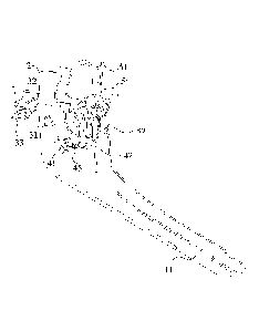
[0040] FIG. 1 is a schematic view of a handle assembly used in a stapler
according to an
embodiment of the present disclosure;
7/ 32
Date Recue/Date Received 2020-06-12
CA 03085637 2020-06-12
[0041] FIGS. 2-3 are schematic views of a handle assembly used in a
conventional
stapler according to a first embodiment of the present disclosure;
[0042] FIG 4 is a schematic view of the handle assembly used in a circumcision
stapler
according to the first embodiment of the present disclosure;
[0043] FIG 5 is a schematic view of the handle assembly in an initial state
according to
the first embodiment of the present disclosure;
[0044] FIG 6 is a schematic view of a slot according to the first embodiment
of the
present disclosure;
[0045] FIG 7 is a stereoscopic view of the handle assembly in the initial
state according
to the first embodiment of the present disclosure;
[0046] FIG 8 is a stereoscopic view of an indicator and a slider in the
initial state
according to the first embodiment of the present disclosure;
[0047] FIGS. 9-11 are schematic views of the handle assembly in the invalid
firing
state according to the first embodiment of the present disclosure;
[0048] FIG 12 is a schematic view of a handle assembly when the indicator
moves to a
second position area according to the first embodiment of the present
disclosure;
[0049] FIGS. 13-15 are schematic views of the handle assembly in a firing
state
according to the first embodiment of the present disclosure;
[0050] FIG 16 is a schematic view of a handle assembly in an initial state
according to
a second embodiment of the present disclosure;
[0051] FIG 17 is an enlarged view of area A in FIG 16;
[0052] FIG 18 is an explosion diagram of the handle assembly according to the
second
embodiment of the present disclosure;
[0053] FIG. 19 is a stereoscopic view of the handle casing according to the
second
embodiment of the present disclosure;
8/ 32
Date Recue/Date Received 2020-06-12
CA 03085637 2020-06-12
[0054] FIG 20 is a front view of the handle assembly in the initial state
according to the
second embodiment of the present disclosure;
[0055] FIGS. 21-22 are schematic views of the handle assembly in invalid
firing state
according to the second embodiment of the present disclosure;
[0056] FIGS. 23-24 are schematic views of the handle assembly in a firing
state
according to the second embodiment of the present disclosure.
DETAILED DESCRIPTION
[0057] In the following, embodiments of the present disclosure will be
described in
detail with reference to the figures. The concept of the present disclosure
can be implemented
in a plurality of forms, and should not be understood to be limited to the
embodiments
described hereafter. In contrary, these embodiments are provided to make the
present
disclosure more comprehensive and understandable, and so the conception of the
embodiments can be conveyed to those skilled in the art fully. Same reference
signs in the
figures refer to same or similar elements, so repeated description of them
will be omitted.
[0058] In order to solve the problems in the prior art, the present disclosure
provides a
handle assembly used for firing of stapler. The handle includes a first handle
component and
a second handle, wherein, the first handle component is provided with a slot
including a first
section and a second section connected with each other. A slider is slidably
located in the slot.
One end of the slider is provided with a first limiting structure. An end
portion of the second
section of the slot is provided with a second limiting structure. A
compression spring is
located between the first limiting structure and the second limiting
structure. A first end of the
second handle is rotatably connected with the first handle component. The
present disclosure
further provides a circular stapler including the handle assembly.
[0059] When the slider is in the first section of the slot, and the first
handle component
9 / 32
Date Recue/Date Received 2020-06-12
CA 03085637 2020-06-12
is rotated in a first direction, the slider is not in contact with the second
handle, therefore, the
second handle is not rotated. When the slider moves to the second section of
the slot by
external force and the first handle component is rotated in the first
direction, the compression
spring becomes deformed, therefore, the slider is in contact with the second
handle and
actuates the second handle to rotate. When the slider is free from the
external force, the
restoring force of the compression spring actuates the slider to return to the
first section of the
slot.
[0060] Thus, the present disclosure prevents the stapler from being fired by
mistake
when the stapler is not ready to be fired, and when in an invalid firing
state, the first handle
component can still be pressed to move and a casing of the stapler is
prevented from being
cracked. The compression spring is located between the slider and the slot,
and a position of
the compression spring is defined by the first limiting structure of the
slider and the second
limiting structure of the first handle component, therefore when the slider is
free from the
external force, the slider can be returned by the action of the compression
spring.
[0061] In the following, two embodiments of the present disclosure are
respectively
described combining the accompanying schematic drawings. FIGS. 1-15 show the
structure
of the stapler and its handle assembly according to a first embodiment of the
present
disclosure, wherein the first handle component includes a first handle, in a
side wall of which
located the slot. FIGS. 16-24 show the structure of the stapler and its handle
assembly
according to a second embodiment of the present disclosure, wherein, the first
handle
component includes a first handle and a handle casing sleeved on outside of
the first handle,
wherein, each of the first handle and the handle casing is provided with one
slot. The slot on
the first handle and the slot on the handle casing are connected with each
other.
[0062] FIG. 1 shows the structure of a stapler according to an embodiment of
the
present disclosure. Wherein, a distal end of the stapler is provided with a
cartridge assembly
/ 32
Date Recue/Date Received 2020-06-12
CA 03085637 2020-06-12
72 and an anvil assembly; a proximal end of the stapler is provided with a
knob and the
handle assembly, outside of which is provided with a handle casing 16. The
firing of the
stapler can be achieved by pressing the handle assembly.
[0063] FIGS. 2-5 show the structure of the handle assembly in the initial
state
according to the first embodiment of the present disclosure, wherein part of
the casing or part
of the assembly is omitted for clear presentation of the structure of the
handle assembly and
its coordination with other parts. In order to achieve the above object, the
handle assembly of
the present disclosure is segmented. The handle assembly is divided into a
first handle
component and a second handle 2. The first handle component includes a first
handle 1, and
only the rotation of the second handle 2 can fire the stapler. The first
handle 1 and the second
handle 2 are rotatably connected. When the first handle 1 and the second
handle 2 are not
linked together, the operator can press the first handle 1, but can neither
actuate the second
handle 2 to rotate, nor fire the stapler. When the first handle 1 and the
second handle 2 are
linked together, the operator can press the first handle 1 to actuate the
second handle 2 to
rotate, thus firing the staple.
[0064] For controlling the linkage state of the first handle 1 and the second
handle 2,
the first handle 1 is further provided with a first slot 41 including a first
section 411 and a
second section 412 connected with each other, and a slider 42; the second
handle 2 includes a
handle contact portion. When the slider 42 is in the first section 411 of the
first slot 41, and
the first handle 1 pressed is rotated in a first direction, the slider 42 is
not in contact with the
handle contact portion, therefore, the second handle 2 is in an insurance
position. That is to
say, despite the rotation of the first handle 1, the stapler will not be
fired, and the stapler is in
the invalid firing state. In this embodiment, the first direction is an
anticlockwise direction as
shown in the FIGS., however, the present disclosure is not limited to it.
Thus, the first handle
1 can be rotated easily when pressed by the doctor, while the second handle 2
will not be
11 / 32
Date Recue/Date Received 2020-06-12
CA 03085637 2020-06-12
actuated. Therefore, the stapler is in the invalid firing state, and the first
handle 1 can be
rotated by a very small force. The doctor can also know the stapler is in the
invalid firing
state through his operation experience and the casing of the stapler will not
be cracked.
[0065] When the slider 42 is in the second section 412 of the first slot 41,
and the first
handle 1 is pressed to be rotated in the first direction, the slider 42 is in
contact with the
handle contact portion and actuates the second handle 2 to be rotated from the
insurance
position to a firing position. When the second handle 2 is rotated
anticlockwise, the second
handle 2 can actuate a staple pushing rod 75 to move to the distal end of the
stapler, to fire the
stapler.
[0066] It should be noted that, the first section 411 and the second section
412 of the
first slot 41 as described in the present disclosure are relative concepts,
not necessarily
indicate two ends of the first slot 41. That is to say, in the perspective
shown in FIG 5, the
first section 411 of the first slot 41 can be located on a right side of the
second section 412.
The relationship between the slider 42 and the handle contact portion 25, when
the first
handle 1 is pressed while the slider 42 in the first section 411 of the first
slot 41 and when the
first handle 1 is pressed while the slider 42 in the second section 421 of the
first slot 41, is
different. When the slider 42 is in the first section 411 of the first slot
41, the slider 42 will
not be in contact with the handle contact portion; when the slider 42 is in
the second section
421 of the first slot 41, the slider 42 will be in contact with the handle
contact portion.
[0067] In the embodiment, the movement of the slider 42 from the first section
411 to
the second section 421 of the first slot 41 is controlled by an indicator 5.
The indicator 5
includes a first end 51, a fixed portion 53 and a second end 42. The first end
51 of the
indicator 5 is provided with a convex portion 54, positioned correspondingly
to a position of
a pulling hook of a pulling sheet 6. The fixed portion 53 of the indicator 5
is rotatably fixed to
the casing 74 of the stapler. The tail of the pulling sheet 6 is fixed to a
screw rod 76 to move
12/ 32
Date Recue/Date Received 2020-06-12
CA 03085637 2020-06-12
along with the screw rod 76. When the knob 71 is rotated in a direction, the
screw rod 76 will
move toward the proximal end of the stapler to actuate the pulling sheet 6 to
move toward the
proximal end of the stapler. The pulling sheet 6 can actuate the first end 51
of the indicator 5
to be rotated in a second direction, so that the first end 51 of the indicator
5 moves from a
first position area to a second position area. Thus, the second end 52 of the
indicator 5
actuates the slider 42 to move from the first section 411 to the second
section 412 of the first
slot 41. In this embodiment, the second direction is a clockwise direction as
shown in the
FIGS., however, the present disclosure is not limited to it. Wherein, a window
is provided on
the instrument body, between the first position area and the second position
area, through
which the position of the first end 51 of the indicator can be observed during
operation. When
the first end 51 of the indicator is in the first position area, the stapler
is in an insurance state
and not ready to be fired. When the first end 51 of the indicator is in the
second position area,
the stapler is ready to be fired. To give a more obvious indication to the
doctor, the window
corresponding to the second position area indicating the stapler being ready
to be fired is
colored green, which is already existed in the prior art.
[0068] For achieving the return of the slider 42 after the slider 42 is free
from the force
exerted by the indicator 5, the slider 42 is further provided with a
compression spring 45.
Specifically, one end of the slider 42 is provided with a first limiting
structure 43; the end
portion of the second section 412 of the first slot 41 is provided with a
second limiting
structure 44. The compression spring 45 is located between the first limiting
structure 43 and
the second limiting structure 44. The end portion of the second section 412 of
the first slot 41
is the end of the second section 412 far from the first section 411, that is
the left position in
FIG 5 herein. When the first end 51 of the indicator 5 moves from the first
position area to
the second position area, the second end 52 of the indicator 5 actuates the
slider 42 to move
from the first section 412 to the second section 412 of the first slot 41,
compressing the
13 / 32
Date Recue/Date Received 2020-06-12
CA 03085637 2020-06-12
compression spring 45 to become deformed. When the external force is released,
the first end
51 of the indicator 5 can return to the first position area, the second end 52
of the indicator 5
is not in contact with the slider 42, therefore, the restoring force of the
compression spring 45
can push the slider 42 to return to the first section 411 of the first slot
41.
[0069] Further, in this embodiment, the first handle includes a cavity 13, two
side walls
of which are respectively provided with two first slots 41. The slider 42
includes two sliding
portions 421 and a contact portion 422 between the two sliding portions
421.The two sliding
portions 421 are movably located on the first slot 41. Two second limiting
structures 44 are
provided on the end portions of the second sections 412 of the two first slots
41, respectively.
Two first limiting structures 43, corresponding to the two second limiting
structures 44, are
provided on the ends of the two sliding portions, respectively. One
compression spring 45 is
provided between each first limiting structure 43 and the corresponding second
limiting
structure 44, respectively. A length of the sliding portion 421 along an
extension direction of
the first slot 41 is greater than a length of the contact portion 422 along
the extension
direction of the first slot 41, to maintain the stability of the slider 42 in
the first slot 41.
[0070] In this embodiment, the first slot 41 connects inside and outside of
the cavity 13
of the first handle 1. That is, the structure of the first slot 41 and the
slider 42 can be seen
from an outer wall of the first handle 1. The compression spring 45 can be
directly installed
outside the first handle 1, and a current position of the slider 42 and a
compressed state of the
compression spring 45 can be seen from the outside of the first handle 1. In
this embodiment,
the first handle 1 is further provided with a handle casing 16 sleeved on the
outside of the
first handle 1. The handle casing 16 is generally made of plastic material,
used to protect the
first handle 1, and has smooth lines to improve the user experience.
[0071] In this embodiment, the first limiting structure 43 and the second
limiting
structure 44 are convex columns, respectively, and two ends of the compression
spring 45 are
14 / 32
Date Recue/Date Received 2020-06-12
CA 03085637 2020-06-12
sleeved on the first limiting structure 43 and the second limiting structure
44 respectively.
Therefore, sizes of the two convex columns are adapted to sizes of the
compression spring 45
to avoid the separation of the compression spring 45 from the convex columns.
In practical
applications, the structure of the limiting structure of the compression
spring 45 is not limited
to this, and other structures are also within the protection scope of the
present disclosure. For
example, the first limiting structure 43 and the second limiting structure 44
may be hanging
hooks, respectively, and two ends of the compression spring 45 are
respectively hung on the
first limiting structure 43 and the second limiting structure 44 to limit the
compression spring
45.
[0072] In this embodiment, a first pin 31 passes through the first handle 1
and the
second handle 2 at the same time, the first pin 31 is fixed to the casing 74
of the stapler, and
the first torsion spring 32 is sleeved on the first pin 31. Two ends of the
first torsion spring 32
are respectively in contact with the casing 74 of the stapler and the second
handle 2. After the
second handle 2 rotates, if the external force is released, the second handle
2 can return.
[0073] Since both the first handle 1 and the second handle 2 rotate around the
first pin
31, the centers of rotation of the first handle 1 and the second handle 2 are
unified, and the
operator's experience is better. In addition, in this embodiment, a second
torsion spring 34
and a second pin 33 are also provided for the return of the first handle 1.
The second pin 33 is
fixed to the casing 74 of the stapler, the second torsion spring 34 is sleeved
on the second pin
33, and the two ends of the second torsion spring 34 are respectively in
contact with the
casing 74 of the stapler and the first handle 1.
[0074] Only one connection method of the first handle 1 and the second handle
2 is
given here, however, the present disclosure is not limited to this, and the
two handles may be
connected in other ways, which are within the protection scope of the present
disclosure. For
example, the second torsion spring and the second pin for the return of the
first handle can be
15 / 32
Date Recue/Date Received 2020-06-12
CA 03085637 2020-06-12
replaced with at least one compression spring. The compression spring is
connected between
the first handle and the casing of the stapler. When the first handle rotates,
the compression
spring becomes deformed, when the first handle is released, the compression
spring is
restored and the first handle returns. Further, a structure having dual
rotation center may be
adopted. For example, in a structure having dual rotation center, the handle
assembly is also
provided with a first torsion spring, a first pin, a second torsion spring and
a second pin shaft.
The first pin is fixed to the second handle, and passes through the first
handle, the first torsion
spring is sleeved on the first pin, and the two ends of the first torsion
spring are respectively
in contact with the first handle and the second handle, which can realize the
return of the first
handle; the second pin is fixed to the casing of the stapler and passes
through the second
handle, the second torsion spring is sleeved on the second pin, and two ends
of the second
torsion spring are respectively in contact with the second handle and the
casing of the stapler
to realize the return of the second handle. The first handle and the second
handle rotate
around the first torsion spring and the second torsion spring, respectively.
[0075] The handle assembly of the present disclosure can be applied not only
to the
conventional circular stapler, but also to a circumcision stapler. For
example, as shown in FIG
4, the structure of the instrument body 8 of the circumcision stapler to which
the handle
assembly is applied is shown. The distal end of the instrument body 8 of the
circumcision
stapler includes a cal _________________________________________________
tlidge assembly 81, and a glans cap assembly (not shown in the figures)
cooperated with the cal ________________________________________________ Li
idge assembly 81 is also provided. When using a circumcision
stapler, the second handle 2 is movably connected to one end of the
circumcision stapler. The
second end of the second handle 2 is cooperated with a staple pushing
component of the
circumcision stapler. When the stapler is ready to be fired, the staple
pushing component is
pushed by the second handle 2 to fire the circumcision stapler.
[0076] The structure of the first slot 41 in this embodiment can be seen in
FIGS. 6-8.
16/ 32
Date Recue/Date Received 2020-06-12
CA 03085637 2020-06-12
Wherein, a height of the second section 412 of the first slot 41 is greater
than a height of the
first section 411, and the first section 411 and the second section 412
smoothly transit through
an inclined plane. Inner wall of the end of the second section 412 is provided
with a support
seat 413 for a convex column; the second limiting structure 44 is located on
the convex pillar
support seat 413, and a height of the support seat 413 is greater than a
height of the second
limiting structure 44. Since the height of the second limiting structure 44
itself is limited by
the compression spring 45, if it is made very large, it cannot be connected to
the compression
spring. Therefore, in this embodiment a convex pillar support seat 413 is
added to provide
better support to the second limiting structure 44.
[0077] FIGS. 9-11 show the structure of the handle assembly in an invalid
firing state
according to this embodiment. In this state, the pulling sheet 6 does not pull
the indicator 5,
so the position of the indicator 5 does not change, and the slider 42 is still
located in the first
section 411 of the first slot 41. The handle contact portion of the second
handle 2 does not
interfere with the slider 42, during the rotation path of the first handle 1.
It should be noted
that, in the initial position, the slider 42 is located at the end of the
first section 411 of the first
slot 41 away from the second section 412, which is the right end position
shown in FIG. 9,
under the action of the compression spring 45. Of course, the second end 52 of
the indicator 5
may also limit the initial position of the slider 42. In this embodiment, the
first end 11 of the
first handle 1 is a grip portion, and the second end 12 includes a connecting
portion; the first
end 21 of the second handle 2 is located inside the cavity of the connecting
portion, and the
second end 22 is in contact with a staple pushing rod 75. At this time, the
stapler is in an
insurance state. Since the torsion force of the second torsion spring 34 is
much smaller than a
firing force, the first handle 1 can be rotated anticlockwise around the first
pin 31 when the
operator applies a small holding force, and the second handle 2 continues to
enter inside the
cavity of the first handle 1, that is, the first handle 1 and the second
handle 2 are in an
17/ 32
Date Recue/Date Received 2020-06-12
CA 03085637 2020-06-12
un-linked state, and the second handle 2 is not be rotated. When the operator
compresses the
first handle 1, the first handle 1 can be easily rotated, but the second
handle 2 is not actuated
to rotate, therefore the stapler cannot be fired. The operator can also get
tactile feedback at
this time, knowing that the first end 51 of the indicator 5 currently has not
reached the second
position area and the stapler has not been fired. When the external force is
released, the first
handle 1 will return by the action of the second torsion spring 34.
[0078] FIG 12 is a schematic view of the first end 51 of the indicator 5
moving to the
second position area according to this embodiment. During this process,
rotating the knob 71
causes the screw rod 76 to actuate the pulling sheet 6 to move toward the
proximal end of the
stapler, and to actuate the first end 51 of the indicator 5 to rotate
clockwise, so that the first
end 51 of the indicator 5 enters the second position area from the first
position area.
Therefore, the second end 52 of the indicator 5 pushes the slider 42 to move
toward the
second section 412 of the first slot 41, so that the first limiting structure
43 approaches the
second limiting structure 44, and compressing the compression spring 45 to
become
deformed. At this time, during the rotation path of the first handle 1, the
handle contact
portion of the second handle 2 will interfere with the slider 42.
[0079] FIGS. 13-15 show the structure of the handle assembly of this
embodiment
when it is in a firing state. When the first handle 1 is compressed to rotate
anticlockwise, the
slider 42 is in contact with the handle contact portion of the second handle 2
and blocks the
second handle 2 from continuing to enter the inner cavity of the first handle
1. As a result, the
second handle 2 and the first handle 1 become linked. The second handle 2
rotates
anticlockwise with the first handle 1, and the second end 22 of the second
handle 2 pushes the
staple pushing rod 75. The staple pushing rod 75 will further push a staple
pushing sheet and
a circular cutter of the stapler, thereby cutting and suturing the tissues to
be operated.
[0080] As can be seen from FIG 13, the compression spring 45 is gradually
compressed
18/ 32
Date Recue/Date Received 2020-06-12
CA 03085637 2020-06-12
during the movement of the slider 42. Further, the second handle 2 is also
provided with a
pulling sheet contacting portion 23. When the second handle 2 rotates from the
insurance
position to the firing position, the pulling sheet contacting portion 23 will
jack the pulling
sheet 6 up at an ejected vertex, so that the pulling hook of the pulling sheet
6 is separated
from the indicator 5. At this time, the indicator 5 returns to the initial
position in the
anticlockwise direction. In this embodiment, a metal sheet 77 is provided at a
position
corresponding to the first end 51 of the indicator 5 in the casing 74 of the
stapler. When the
indicator 5 returns to the initial position, it will collide with the metal
sheet 77 to make a
sound, prompting the operator that the indicator has returned. Since the first
end 51 of the
indicator 5 returns to the first position area, the second end 52 of the
indicator 5 is separated
from the slider 42 after releasing the first handle 1. Then, after the
indicator 5 returns, since
the indicator 5 no longer exerts force on the slider 42, the deforming force
of the compression
spring 45 when restoring to the initial state can push the slider 42 to slide
toward the first
section 411 of the first slot 41 again, and return to the initial position.
The second handle 2
also returns to the initial position under the restoring force of the first
torsion spring 32. Since
the first handle 1 is meshed with the second handle 2 under the action of the
slider, it firstly
returns with the second handle 2, and at the same time returns under the
action of the second
torsion spring 34.
[0081] FIGS. 16 ¨ 24 show a schematic view of the structure of the stapler and
the
handle casing according to a second embodiment of the present disclosure. The
difference
between this embodiment and the first embodiment is that the first handle
component
includes a first handle 1 and a handle casing 16, the first handle 1 is
provided with a first slot
41, and the handle casing 16 is provided with a second slot 161. Moreover, the
first slot 41 on
the first handle 1 is connected with the second slot 161 on the handle casing
16, and the
second limiting structure 44 is located at the end of the second section of
the second slot 161.
19/ 32
Date Recue/Date Received 2020-06-12
CA 03085637 2020-06-12
[0082] The first section of the second slot 161 corresponds to the first
section 411 of the
first slot 41, the second section of the second slot 161 corresponds to the
second section 412
of the first slot 41, and the slider 42 passing through the first slot 41 is
embedded in the
second slot 161. The second handle 2 includes a handle contact portion; when
the slider 42 is
located in the first section of the second slot 161 and the first handle 1 is
compressed to rotate
in the first direction, the slider 42 is not in contact with the handle
contact portion, the second
handle 2 is in the insurance position, that is, although the first handle 1
rotates, it will not fire
the stapler and the stapler is in the invalid firing state. Therefore, when
the doctor presses the
first handle 1 and the handle casing 16, the first handle 1 and the handle
casing 16 can be
easily rotated, but the second handle 2 will not be actuated. At the same
time, since is the
stapler in the invalid firing state, the holding force of the first handle 1
is very small. The
doctor can also learn through this operation experience that the stapler is
not fired, and the
casing of the stapler is prevented from being cracked.
[0083] When the slider 42 is located in the second section of the second slot
161, and
the first handle 1 and the handle casing 16 are rotated in the anticlockwise
direction, the
slider 42 is in contact with the handle contact portion and actuates the
second handle 2 to
rotate from the insurance position to the firing position. When the second
handle 2 is rotated
in the anticlockwise direction, it simultaneously pushes the staple pushing
rod 75 to move
toward the distal end of the stapler, thereby actuating the stapler to be
fired.
[0084] It should be noted that the first section and the second section of the
second slot
161 in the present disclosure are also relative concepts, not necessarily
indicate the two ends
of the second slot 161. That is say, in the perspective shown in FIG 17, the
first section of the
second slot 161 is located on the right side of the second section. When the
slider 42 is
located in the first section of the second slot 161, it will not be in contact
with the handle
contact portion, and when the slider 42 is located in the second section of
the second slot 161,
20 / 32
Date Recue/Date Received 2020-06-12
CA 03085637 2020-06-12
it will be in contact with the handle contact portion.
[0085] In this embodiment, the movement of the slider 42 from the first
section to the
second section of the second slot 161 may also be controlled by the indicator
5. When the
knob 71 is rotated in one direction, the screw rod 76 will move toward the
proximal end of
the stapler, actuating the pulling sheet 6 to move toward the proximal end of
the stapler, and
the pulling hook of the pulling sheet 6 may actuate the first end 51 of the
indicator 5 to rotate
in the second direction. Therefore, the second end 52 of the indicator 5 can
push the slider 42
to move from the first section to the second section of the second slot 161,
when the first end
51 of the indicator 5 moves from the first position area to the second
position area.
[0086] In this embodiment, one end of the slider 42 is provided with a first
limiting
structure 43, and the end of the second section of the second slot 161 is
provided with a
second limiting structure 44. A compression spring 45 is located between the
first limiting
structure 43 and the second limiting structures 44. Herein, the end of the
second section of the
second slot 161 is the end of the second section away from the first section
of the second slot
161, that is, the left position in FIG 17. When the first end 51 of the
indicator 5 moves from
the first position area to the second position area, the second end 52 of the
indicator 5 pushes
the slider 42 to compress the compression spring 45 to become deformed. When
the external
force is released, the first end 51 of the indicator 5 can return to the first
position area,
therefore, the restoring force of the compression spring 45 can push the
slider 42 to return to
the first section of the second slot 161.
[0087] Further, in this embodiment, the first handle 1 includes a first cavity
13, two side
walls of the first cavity 13 are respectively provided with two first slots
41, and the handle
casing 16 is correspondingly provided with two second slots 161. The slider 42
includes two
sliding portions 421 and a contact portion 422 between the sliding portions
421. The two
sliding portions 421 are slidably located in the two second slots 161,
respectively. The end
21/ 32
Date Recue/Date Received 2020-06-12
CA 03085637 2020-06-12
portions of the second sections of the two second slot 161 are respectively
provided with two
second limiting structures 44. The ends of the two sliding portions are
respectively provided
with two first limiting structures 43, corresponding to the two second
limiting structures 44.
One compression spring 45 is located between each first limiting structure 43
and the
corresponding second limiting structure 44. And, a length of the sliding
portion 421 along an
extension direction of the second slot 161 is greater than a length of the
contact portion 422
along the extension direction of the second slot 161, to maintain the
stability of the slider 42
in the first slot 41.
[0088] In this embodiment, by locating the compression spring 45 between the
handle
casing 16 and the slider 42, the working state of the compression spring 45
can be directly
seen from the outside of the handle casing 16, which is convenient for
inspection. The handle
casing 16 does not need to be disassembled during installation and
replacement, so that the
installation and maintenance of the handle assembly and even the stapler are
more
cost-effective.
[0089] The structure of the handle casing 16 and the cooperation relationship
with the
stapler can be specifically referred to in FIGS. 18 and 19. The proximal end
of the handle
casing 16 is a grip portion, and the distal end is cooperated with the casing
74 of the stapler.
The second slot 161 is opened at the distal end of the handle casing 16 and
connected with an
upper surface of the handle casing 16. Herein, the upper surface of the handle
casing 16 is a
top end surface of the handle casing 16 in the perspective of FIG 5. That is,
the second slot
161 is a slot with an upper opening, and the compression spring 45 can be
directly installed
and removed from an upper portion the handle casing 16. Due to the position-
limiting effect
of the two limiting structures, there is no need to worry about the position
deviation of the
compression spring 45 during normal use. One side of the distal end of the
handle casing 16
is in contact with the casing 74 of the stapler. A position of casing 74 of
the stapler
22 / 32
Date Recue/Date Received 2020-06-12
CA 03085637 2020-06-12
corresponding to the other side of the distal end of the handle casing 16 is
provided with a
handle opening 749 to accommodate the handle casing 16 when being rotated
anticlockwise.
[0090] In this embodiment, the first limiting structure 43 and the second
limiting
structure 44 are convex columns respectively. The two ends of the compression
spring 45 are
respectively sleeved on the first limiting structure 43 and the second
limiting structure 44.
Therefore, the sizes of the two convex columns are adapted to the size of the
compression
spring 45 to avoid the separation of the compression spring 45 from the convex
columns. In
practical application, the structure of the limiting structure of the
compression spring 45 is
not limited to this, and other structures are also within the protection scope
of the present
disclosure. For example, the first limiting structure 43 and the second
limiting structure 44
can be hanging hooks respectively, and the two ends of the compression spring
45 are
respectively hung on the first limiting structure 43 and the second limiting
structure 44 to
limit the compression spring 45.
[0091] FIGS.21 and 22 show the structure of the handle assembly in an invalid
firing
state according to this embodiment. In this state, the pulling sheet 6 does
not pull the
indicator 5, so the position of the indicator 5 does not change, and the
slider 42 is still located
in the first section of the second slot 161. The handle contact portion of the
second handle 2
does not interfere with the slider 42, during the rotation path of the first
handle 1. It should be
noted that, in the initial position, the slider 42 is located at the end of
the first section of the
second slot 161 away from the second section, which is the right end position
shown in the
figure, under the action of the compression spring 45. Of course, the second
end 52 of the
indicator 5 may limit the initial position of the slider 42. At this time, the
stapler is in the
insurance state. Since the torsion force of the second torsion spring 34 is
much smaller than
the firing force, the first handle 1 can be rotated anticlockwise around the
first pin 31 when
the operator applies a small holding force, and the second handle 2 continues
to enter inside
23 / 32
Date Recue/Date Received 2020-06-12
CA 03085637 2020-06-12
the cavity of the first handle 1, that is, the first handle 1 and the second
handle 2 are in an
un-linked state, and the second handle 2 is not be rotated. When the operator
compresses the
first handle 1, the first handle 1 can be easily rotated, but the second
handle 2 is not actuated
to rotate, therefore the stapler cannot be fired. The operator can also get
tactile feedback at
this time, knowing that the first end 51 of the current indicator 5 has not
reached the second
position area and the stapler is not fired. When the external force is
released, the first handle 1
will be returned by the action of the second torsion spring 34.
[0092] FIGS. 23 and 24 show the structure of the handle assembly in the firing
state
according to this embodiment. During this process, turning the knob 71 causes
the screw rod
76 to actuate the pulling sheet 6 to move toward the proximal end of the
stapler, and to
actuate the first end 51 of the indicator 5 to rotate clockwise, so that the
first end 51 of the
indicator 5 enters the second position area from the first position area.
Therefore, the second
end 52 of the indicator 5 actuates the slider 42 to move toward the second
section of the
second slot 161, so that the first limiting structure 43 approaches the second
limiting
structure 44. When the first handle 1 is rotated anticlockwise, the slider 42
can be in contact
with the handle contact portion 25 and blocks the second handle 2 from
continuing to enter
the inner cavity of the first handle 1. As a result, the second handle 2 and
the first handle 1
become linked. The second handle 2 is rotated anticlockwise with the first
handle 1, and the
second end 22 of the second handle 2 pushes the staple pushing rod 75. The
staple pushing
rod 75 will further push a staple pushing sheet and a circular cutter of the
stapler, thereby
cutting and suturing the tissues to be operated.
[0093] As can be seen from the figure, the compression spring 45 is gradually
compressed during the movement of the slider 42. When the stapler is fired,
the pulling sheet
contacting portion 23 will jack the pulling sheet 6 up at the ejected vertex,
so that the pulling
hook of the pulling sheet 6 is separated from the indicator 5. At this time,
the indicator 5
24 / 32
Date Recue/Date Received 2020-06-12
CA 03085637 2020-06-12
returns to the initial position in the anticlockwise direction. In this
embodiment, a metal sheet
77 is provided at a position corresponding to the first end 51 of the
indicator 5 in the casing
74 of the stapler. When the indicator 5 returns to the initial position, it
will collide with the
metal sheet 77 to make a sound, prompting the operator that the indicator has
returned. Since
the first end 51 of the indicator 5 returns to the first position area, the
second end 52 of the
indicator 5 is separated from the slider 42 after releasing the first handle
1. Then, after the
external force of the pointer 5 is released, the deforming force of the
compression spring 45
when restoring to the initial state can push the slider 42 to slide toward the
first end of the
second slot 161 again, and return to the initial position. The second handle 2
also returns to
the initial position under the restoring force of the first torsion spring 32.
Since the first
handle 1 is meshed with the second handle 2 under the action of the slider, it
firstly returns
with the second handle 2 and at the same time returns under the action of the
second torsion
spring 34.
[0094] The present disclosure further provides a stapler, including the handle
assembly.
When the stapler is not ready to be fired, the second handle cannot be
actuated by the first
handle, and the stapler won't be fired. The doctor can also judge whether the
stapler is ready
to be fired or not according to his operation experience. The second handle
can only be
actuated by the first handle when the stapler is ready to be fired, to fire
the staple. Therefore,
the stapler is prevented from being fired by mistake, and the casing of the
stapler is prevented
from being cracked at the same time. The stapler can control the linkage state
of the first
handle and the second handle by the moving position of the slider. After the
firing is
completed, the slider can return to the initial position by the return action
of the compression
spring.
[0095] The handle assembly and the stapler including the same has the
following
advantages.
25 / 32
Date Recue/Date Received 2020-06-12
CA 03085637 2020-06-12
[0096] In the present disclosure, the handle assembly includes the first
handle
component and the second handle, the linkage state of which can be controlled
by the moving
position of the slider and only the rotation of the second handle can fire the
stapler, so as to
avoid being fired by mistake when the stapler is not ready to be fired, and
when in the invalid
firing state, the first handle component can still be pressed and the casing
of the stapler is
prevented from being cracked; the compression spring is located between the
slider and the
slot, and the position of the compression spring is defined by a first
limiting structure of the
slider and a second limiting structure of the first handle component,
therefore when the slider
is free from the external force, the slider can be returned by the action of
the compression
spring.
[0097] The above is a detailed description of the present disclosure in
connection with
the specific preferred embodiments, and the specific embodiments of the
present disclosure
are not limited to the description. Modifications and substitutions can be
made without
departing from the spirit and scope of the present disclosure.
26 / 32
Date Recue/Date Received 2020-06-12