Note: Descriptions are shown in the official language in which they were submitted.
VERTICAL FARM WITH REVOLVING CAROUSEL
FIELD OF THE INVENTION
100011 The present invention pertains to farming in general and to indoor
vertical farms
in particular.
BACKGROUND
100021 For many years, growers have used vertical farm systems to grow
vegetation in
urban, air and space-constrained areas. There are at least four types of
vertical indoor
farming systems: Soil based system, growing crops in trays with soil as an
aggregate
medium; Hydroponic system, growing crops with their roots submersed in a
nutrient water
solution; Aquaponic system, which is the same as hydroponic system, but using
fish in
tanks to fertilize the water, which is then used to fertilize crop's roots;
and the last
category, which is somewhat more complex, but with many advantages over other
systems,
is the Aeroponic system. This system involves growing plant's roots in an air
or mist
environment without the use of soil or an aggregate medium (known as
geoponics). The
combination of root exposure to air along with oxygen and nutrient rich water
spray
supplied by the system, promotes healthy plant growth.
!OW] The Aeroponic technology derives partly from systems designed to grow
crops on
the moon. Originally developed by Ed hardwood of Ithaca, New York, the term
"vertical
farming" has not been around long. It refers to a method of growing crops,
usually without
soil or natural light, in beds stacked vertically inside a controlled-
environment building.
The credit for coining the term seems to belong to Dickson D. Despommier,
Ph.D., a
professor (now emeritus) of parasitology and environmental science at Columbia
University Medical School and the author of "The Vertical Farm: Feeding the
World in the
21st Century," D. Despommier, October 2011, Thomas Dunne Books/St. Martin's
Press.
1
CA 3085884 2021-06-23
_ _
[0004] As Dickson D. Despommier explains in his book "The Vertical Farm": "The
interior
space is its own sealed-off world; nothing inside the Aeroponic vertical-farm
buildings is
uncontrolled. Countless algorithm-driven computer commands combine to induce
the
greens to grow, night and day, so that a crop can go from seed to shoot to
harvest in as little
as eighteen days. Every known influence on the plant's wellbeing is measured,
adjusted, re-
measured and thousands of sensing devices monitor what's going on. In short,
each plant
grows at the pinnacle of a trembling heap of tightly focused and
hypersensitive data. The
temperature, humidity, and CO2 content of the air; the lighting and the
intensity thereof;
the nutrient solution, pH, and electro-conductivity of the water; the plant
growth rate, the
shape and size and complexion of the leaves¨all these factors and many others
are
continuously tracked every moment of day and night, year around".
[0005] Many Aeroponic Vertical type farms already exist and every year, new
ones are
being built worldwide. Notable examples include: AerofarmTM in Newark, New
Jersey;
Green Spirit FarmsTM in New Buffalo, Michigan; Sky GreensTM in Singapore;
FarmedHereTM in
Louisville, Kentucky (planning 20 new facilities across country); Vertical
Farm systems;
VeriGrowTM, Doha Qatar; and Scissartail FarmsTM, Tusla, Oklahoma.
[0006] Some potential advantages of vertical Aeroponic farming systems are
described as
follows. The space: growing crops in an enclosed building or space, sealed off
from outside
and in a controlled environment, mitigates invasion of pesticides and need for
GMO. An
Aeroponic vertical farm occupies just a fraction of the space of a normal farm
and produces
year-round, high quality organic crops with better yields. The towers with
their multiple
tray levels can be made significantly higher than in other systems as there is
little weight of
nutrient water to weigh down the support structures. Yields: The Aeroponic
farm operates
day and night, year around and can produce a crop cycle representing 12 to 18
harvests per
year, producing continuous guaranteed consistency of crop quality year around.
Water
consumption: The Aeroponic farm uses 95% less water than a normal field farm
and 40%
less water than a hydroponic farm, making it suitable for areas where water
shortage is a
problem. Lighting: Plants do not necessarily need the sun; they use only a
fraction of sun's
2
Date Recue/Date Received 2020-07-06
spectrum for their photosynthesis. The Aeroponic farm may use LED light or
other-sourced
artificial light to create a specific light spectrum for each plant in the
most efficient manner.
Clean crop: Because the interior of the Aeroponic farm is substantially
isolated from any
outside dirt, bacteria, etc. and crops are not grown in a soil based medium,
crops are clean
and ready for use and consumption when leaving the farm. Location: The
Aeroponic farm
may be located near a city center, which mitigates major transportation cost,
especially
during winter months when the crops would otherwise be imported from warmer
climate
locations.
[0007] Various types of conventional Aeroponic systems differ in the plant
support
geometry and method of delivery of water nutrient solution. Included among
these various
types are those using a nutrient film technique in which a thin film of
nutrient solution is
caused to flow by net pots in gutter type support geometry. Deep flow systems
use misters
to oxygenate and distribute the nutrients and are termed deep flow because
they
incorporate a riser into the grow chamber to prevent all nutrients from
draining out.
Bubbler Aeroponic systems are like a bucket deep flow Aeroponic system in that
the roots
hang into the nutrient in the bottom while being sprayed by misters above
and/or exposed
to bubbles from air stones below. Vertical flow systems use a misting or drip
distribution of
nutrients by gravity feed.
[0008] One of the shortcoming of existing vertical farming systems, including
Aeroponic
systems, is the ability to produce crops cost effectively. Even though
Aeroponic vertical
farm systems have been sprouting and continue to sprout worldwide in the last
two
decades, they have not been around very long. On one hand, the Aeroponic
system is based
on some very sophisticated technology; on the other hand, it is using very
basic physical
principles to operate the farms. Operating technology presently used in
typical commercial
vertical Aeroponic farm settings is still evolving. Using very large buildings
to house tall
vertical grow towers and using large travel path areas for forklifts and
transport to and
from crop processing rooms, these buildings are expensive to heat, cool,
needing elaborate
set ups for air treatment and control. The existing production process of
harvesting, de-
3
Date Recue/Date Received 2020-07-06
rooting, cleaning, re-seeding and packaging is still quite labour intensive
and time
consuming, where much of the work is still done by hand, with very little
presence and help
of today's automated technology. The major cost factors in growing crops in
Aeroponic
vertical farm systems and buildings, is the energy requirement to run these
farms for
operation of LED lighting 24/7 year around, as well as heating, cooling and
air control, thus
making it presently difficult for the Aeroponic farms to run a profitable
business.
[0009] Accordingly, there is a need to run and operate Aeroponic farm systems
more
efficiently and cost effective by introducing new technology and operating
systems, as well
as mitigating energy consumption.
[0010] This background information is provided to reveal information believed
by the
applicant to be of possible relevance to the present invention. No admission
is necessarily
intended, nor should be construed, that any of the preceding information
constitutes prior
art against the present invention.
SUMMARY
[0011] An object of embodiments of the present invention is to provide a
vertical farm
that presents one or more operational efficiencies, such as space and
transport efficiencies,
that are not currently present in the art.
[0012] Embodiments of the present invention provide for a commercial farm,
which
embodies a circular carousel type multi story level vertical Aeroponic system
situated in an
circular, octagonal, or similarly shaped tower building, sealed from outside.
Positive
interior air pressure may be produced to eliminate intrusion of outside air
impurities. The
interior systems may include the following interdependent components: a
revolving
carousel platform base with its specifically for this system designed vertical
grow
towers, the deployable crop grow trays and a stationary crop tray retrieving
elevator.
4
Date Recue/Date Received 2020-07-06
[0013] The concept of the revolving carousel platform base can be regarded, by
way of
illustration, as being similar to the old fashion carousel slide projector,
with slides
positioned within the carousel to be viewed independently, one at a time.
Specifically for
this carousel platform there are provided a plurality of vertical grow towers,
positioned
next to each other with little to no spacing between them. Each tower includes
multiple
crop growing trays stacked on top of each other. The towers travel on a
platform via a
track system. The towers may be disposed next to (e.g. touching or nearly
touching) each
other. However, the towers can be separated from each other one at the time,
for example
by a width of one vertical tower, by moving towers on the track system. The
movement can
be done for purposes of servicing, maintenance and general operation access.
Like in a slide
projector, the platform base revolves to give access of one vertical tower at
a time to a
stationary retrieving elevator for retracting a plurality of crop growing tray
levels, for
example one at the time, and delivering the trays to a processing area,
situated directly
below the retrieving elevator structure.
[0014] In various embodiments, Crop growing trays, representing one of
multiple
sectors of a platform carousel, are located in grow tower frames. The frames
are purpose
built and may hold multiple vertical rows of said crop growing trays. The crop
growing
trays may consist of: a self-draining base tray, metal framing situated on top
of trays to
hold crop trays, removable crop trays to hold growing crops and a nutritional
spray
system at least partially located within the enclosed root space. The main
supply of
nutrients and oxygen may be located in carousel's narrow inner circle ring.
The supply
may be delivered to each tray base via automatic quick connect fittings,
situated at the
narrow (inner-facing) part of the base tray. The crop growing trays, which are
designed to
fit into their frame structure, can be deployed by sliding or rolling off
their vertical frame
slot via crop tray retrieving elevator. As the carousel platform rotates, one
frame of
vertically located crop growing trays is exposed at a time to the retrieving
elevator.
[0015] In various embodiments, a stationary crop tray retrieving elevator is
provided.
Operation of this elevator can be understood, in some embodiments, as being
similar to the
Date Recue/Date Received 2020-07-06
action of opening drawers of a tall cabinet to retrieve their content. The
retrieving elevator
which is situated above the crop processing area operates vertically and
horizontally, via a
deployable platform to automatically retract rows of crop trays, one row at a
time. The
trays, once retracted, may be delivered downward to a processing area by
lowering the
crop tray row, using the elevator. At the processing area, the crops in the
trays can be
harvested, de-rooted, cleaned and packaged. The trays can be re-seeded or re-
planted and
then returned back to the corresponding grow tower opening it was retracted
from, or to
another location.
[0016] According to embodiments of the present invention, there is provided a
vertical
farm system comprising: a building enclosure; a circular shape revolving base
platform
(BP); a plurality of grow towers (GT) and a crop retrieving elevator (20). The
base
platform is rotatably mounted within the building enclosure and is configured
to rotate
about a central axis under mechanical power; The plurality of grow towers (GT)
are
mounted on the base platform and extend radially outward. Each one of the
plurality of
grow towers includes a plurality of crop bins (19) which are horizontally
movably mounted
within, and configured for insertion into and removal from, said one of the
plurality of grow
towers. The crop retrieving elevator (20) includes a movable platform (20A).
The
platform is vertically movable to align with a selected bin of the plurality
of crop bins. The
platform is horizontally movable between a retracted position and a protracted
position.
In the protracted position, the platform is extended toward the selected bin
to support the
selected bin during said insertion into or removal from a corresponding one of
the plurality
of grow towers. In the retracted position, the platform is horizontally
aligned within the
crop retrieving elevator to facilitate vertical movement thereof.
[0017] Embodiments have been described above in conjunctions with aspects of
the
present invention upon which they can be implemented. Those skilled in the art
will
appreciate that embodiments may be implemented in conjunction with the aspect
with
which they are described, but may also be implemented with other embodiments
of that
aspect. When embodiments are mutually exclusive, or are otherwise incompatible
with
6
Date Recue/Date Received 2020-07-06
each other, it will be apparent to those skilled in the art. Some embodiments
may be
described in relation to one aspect, but may also be applicable to other
aspects, as will be
apparent to those of skill in the art.
BRIEF DESCRIPTION OF THE DRAWINGS
[0018] Further features and advantages of the present invention will become
apparent
from the following detailed description, taken in combination with the
appended drawings,
in which:
[0019] Drawing 1 Shows a space comparison of a prior art field farm and a
vertical farm
according to an embodiment of the present invention, producing approximately
the same
amount of produce per year.
[0020] Drawing 2 Represents a conceptual drawing of a prior art vertical farm
building,
its vertical grow towers and needed travel corridors for transporting crop
trays to and
from the processing area, as well as a vertical farm building according to an
embodiment of
the present invention, with its vertical grow towers positioned next to each
other in a cube
configuration, and a travel corridor for maintenance and servicing of said
towers.
[0021] Drawing 3 Is a conceptual drawing of prior art vertical farm and cubic
farm
variations, as well as the carousel type circular vertical farm design
according to
embodiments of the present invention, showing sizes of spaces they occupy,
number of
crops they produce and the space/crop ratio for each variation.
[0022] Drawing 4 Is a conceptual drawing showing a cross section and a 3D
drawing of
the rotating vertical carousel platform indicating vertical grow towers and
inner circle
multilevel ring platforms, according to embodiments of the present invention.
[0023] Drawing 5 Depicts a conceptual cut-away 3D drawing of carousel type
vertical
farm, according to embodiments of the present invention, showing a revolving
base
platform with its inner ring options, plurality of grow towers moving on the
revolving base
7
Date Recue/Date Received 2020-07-06
platform, as well as ceiling and floor tracks on which the base platform and
grow towers are
traveling.
[0024] Drawing 6 Is a Schematic depiction of a floor plan showing the crop
growing
tower structure with its typical crop tray sizes, as well as three elevations
of the tower,
according to embodiments of the present invention.
[0025] Drawing 7 Is a schematic depiction of a self-draining tray base, as
well as
connections to the vertical drain and a typical nutrient supply quick connect
connection to
supply lines, according to embodiments of the present invention.
[0026] Drawing 8 Is a conceptual 3D drawing of a typical tray base showing
multiple
crop nutrient and oxygen spray lines and spray nozzles within the tray base as
well as
connections to corresponding supply lines, according to embodiments of the
present
invention.
[0027] Drawing 9 Is a conceptual 3D drawing showing a typical tray base, with
crop tray
carrying metal frames attached to the tray base as well as deployable crop
trays with corps
at different grow stages, according to embodiments of the present invention.
[0028] Drawing 10 Is a schematic cross section through a typical grow tower,
showing
the tower frames with their horizontal travel tracks, tray base with its metal
frames, crop's
root cavity and crop trays with ready to harvest crops, lighting, CO2 spray
outlet, as well as
supply connections from the main supply lines, according to embodiments of the
present
invention.
[0029] Drawing 11 Shows a schematic configuration of the horizontal crop tray
travel
tracks in a typical grow tower level and elevation of the a vertical farm
tower showing
multiple crop tray level divisions, according to embodiments of the present
invention.
[0030] Drawing 12 Is a floor plan and a 3D drawing showing the concept of the
vertical
farm design, encompassing the overall enclosure with its attached enclosed
area for
8
Date Recue/Date Received 2020-07-06
retrieving grow trays from vertical towers for harvesting to reseeding
activities, according
to embodiments of the present invention.
[0031] Drawing 13 Is a conceptual cross section/elevation depicting the
process of a crop
tray level being retrieved by the stationary crop retrieving elevator, which
is located in the
crop processing area, and lowered to the processing area for harvesting,
cleaning, reseeding
and packaging, according to embodiments of the present invention.
[0032] Drawing 14 Is a 3D conceptual drawing showing the "elevator platform"
being
raised by the crop retrieving elevator to line up with the crop tray level in
the grow tower,
which is designated to be retrieved, according to embodiments of the present
invention.
[0033] Drawing 15 Is a 3D conceptual drawing showing the elevator platform
being
protracted and set up by the crop retrieving elevator to line up with the crop
tray level in
the grow tower, in order to retrieve the crop tray level, according to
embodiments of the
present invention.
[0034] Drawing 16 Is a 3D conceptual drawing showing the elevator platform
retrieving
the designated crop tray level with its base by pulling it out of the grow
tower like a drawer
out of a cabinet, according to embodiments of the present invention.
[0035] Drawing 17 Is a 3D conceptual drawing showing the elevator platform
with its
retrieved crop tray level to be lowered to the crop processing area, located
below the
retrieving elevator.
[0036] Drawing 18 Is a 3D conceptual drawing depicting workers in the docking
and crop
processing area de-rooting, harvesting, reseeding and packaging harvested
crops, according
to embodiments of the present invention.
[0037] Drawing 19 Is a 3D conceptual drawing depicting workers in the crop
processing
area cleaning and reseeding crop trays and position them onto a base of a
typical crop tray
level, according to embodiments of the present invention.
9
Date Recue/Date Received 2020-07-06
[0038] Drawing 20 Is a 3D conceptual drawing showing the reseeded crop tray
level
being raised by the "elevator platform" to line up with the crop tray level in
the grow tower,
which it was retrieved from, to be returned back to its original location,
according to
embodiments of the present invention.
[0039] Drawing 21 Is a 3D conceptual drawing showing the "elevator platform"
being
raised or lowered by the crop retrieving elevator to line up with the next
crop tray level in
the grow tower, which is designated to be retrieved, according to embodiments
of the
present invention.
[0040] Drawing 22 Is a 3D conceptual drawing of the Carousel type vertical
farm, with a
vertically moving retrieving elevator to move produce to harvesting and
seeding area and
then transport the harvested crop with elevators to the holding storage and
delivery area,
according to embodiments of the present invention.
[0041] Drawing 23 Is a schematic floor plan and a cross section drawing of a
typical two
level vertical farm set up depicting the revolving carousel towers, crop
retrieving elevators,
the crop processing area, as well as elevators to holding and delivery bay,
according to
embodiments of the present invention.
[0042] Drawing 24 Is a schematic depiction of the crop drainage and recovery
system as
well as the central supply system for crop nutrient liquid, oxygen and CO2 to
be supplied to
every vertical tower main connection, according to embodiments of the present
invention.
[0043] Drawing 25 Is a schematic depiction of the central ring platform
elevations and a
partial 3D drawing of the platforms to house the main crop supply system,
according to
embodiments of the present invention.
[0044] It will be noted that throughout the appended drawings, like features
are
identified by like reference numerals.
Date Recue/Date Received 2020-07-06
DETAILED DESCRIPTION
[0045] As used herein, the term "about" should be read as including variation
from the
nominal value, for example, a +/-10% variation from the nominal value. It is
to be
understood that such a variation is always included in a given value provided
herein,
whether or not it is specifically referred to.
[0046] The technology wording used herein is for the purpose of describing
specific
embodiments, not intended to be limiting to the invention. The terms "and/or"
includes all
combination of one or more of listed items. The singular words "a", "an", and
"the" are
intended to include singular and plural forms. The terms "comprises,
comprising",
"represents, representing", "consist of, consisting, encompassing" specify the
presence of
stated features, operations, elements and components, but do not exclude the
presence of
other features, operations, elements, components and groups thereof. It is
clarified that by
describing the farm of the present invention, a number of processes and
functions are
disclosed. Each has individual benefit and each can be used in conjunction
with one, more
or all of the other disclosed features, operations or components.
[0047] The term "VECTAR" refers to a Vertical Enclosed Carousel Tower Ranch
farm or a
plurality of such farms, and this term is generally used to refer to
embodiments of the
present invention, whether or not the referenced farm is so named, is
completely enclosed
or can be considered a "ranch" as the term may be interpreted. In other words,
the term
"VECTAR" is not intended to be limiting in any way, but rather is used simply
to make
reference to embodiments of the present invention.
[0048] The present disclosure is to be considered as specification and
clarification of the
invention and parts thereof, and it is not intended to limit the invention to
the specific
embodiments as illustrated on the drawings, outlined figures, numbers or
description. It is
understood that the following drawings illustrating and or describing the
present invention
are considered as an exemplification of the invention showing the schematic or
conceptual
nature of the invention and are not necessarily intended to limit the
invention to any
11
Date Recue/Date Received 2020-07-06
specific embodiments, the final construction of the present invention and to
specifics of the
drawing description.
[0049] For the purpose of explanation in the following description, numerous
specific
details and functions are set forth in order to provide a thorough
understanding of the
present invention. To make the description of the VECTAR farm invention easier
to
comprehend, it is understood that the VECTAR farm detailed description will be
written in
sequence, providing information, discussions and clarifications, following the
progressional
drawing numbers in sequence from 1 to 25. Although the invention is described
with
respect to various drawings used by way of example, it should be understood
that the
invention is not necessarily limited to the particular configurations as
illustrated in the
drawings. Rather, the drawings should be regarded as an example only.
[0050] Embodiments of the present invention may provide for a notable
improvement of
productivity in enclosed Aeroponic vertical farms, growing vegetables and
fruits in
plurality of trays stacked on top of each other in modular towers. Embodiments
may
provide for one or more of: reduced operation costs, increased production
efficiency, and
decreased labour costs, thus potentially making growing and processing of
crops in an
Aeroponic system more efficient and more cost effective.
[0051] Some effects of the present invention in comparison with the prior art,
including
differences in space usage, will first be described with respect to Drawings 1
to 3.
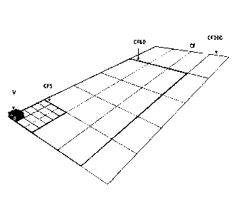
[0052] DRAWING 1
[0053] Having regard now to Drawing 1, it is important to understand why
Aeroponic
vertical farms such as the VECTAR farm have physical advantages to
conventional field
farms. For example, a four story high VECTAR farm V building with a footprint
of 14,400 sq.
feet (120' x 120'), equivalent to 1/3 of one acre, containing 15 crop levels,
encompasses
216,000 sq. feet of crop surface, which is equivalent to five acres of a field
farm crop surface
CF5. Conventional field farms typically produce one harvest/year, sometimes
two
12
Date Recue/Date Received 2020-07-06
(depending on the weather and soil conditions), while the Aeroponic farms such
as
VECTAR may potentially continuously produce 12 and up to 20 harvests/year.
Twelve
VECTAR harvests/year may be roughly equivalent to a 60 acre field farm
production CF60
and 20 VECTAR harvests/year may be roughly equivalent to a 100 acre
conventional field
farm production CF100. This does not include travel roads around and between
crop rows
and fuel driven equipment and machinery, needed to service and maintain the
said
conventional field farms.
[0054] Conventional field farms CF, including organic farms, are heavily
effected by: the
rain, temperature, storms, floods or droughts, pollution, soil conditions, air
pesticide
exposure, soil pesticide exposure, GM0s, water irrigation, high manual labour,
fuel driven
equipment, land erosion created by severe weather and many others. All these
elements
have a significant effect on conventional filed farms, jeopardizing either the
quality of their
crops, unpredictability of their harvest, their harvest size, or even total
destruction of their
crops.
[0055] Aeroponic farms such as VECTAR farm V may not necessarily be as
affected by the
pollution, multiple pesticide chemicals, weather, big storms, floods or
droughts as
conventional farms. Versions of such farms which are completely enclosed and
which may
use only organic seeds, may potentially produce GMO and pesticide free crops,
with crop
quality consistency and continuous harvest predictability.
[0056] DRAWING 2
[0057] Drawing 2 illustrates a schematic floor plan and a 3D drawing depicting
a
traditional vertical farm, including a prior Aeroponic farm set up, as well as
a cubic VECTAR
farm according to an embodiment of the present invention. As a comparison, a
traditional
vertical farm TVF with the building enclosure TVF1 is shown occupying 18,000
sq. feet,
encompassing a plurality of vertical grow towers TVF2, with typical travel
spaces TVF3
between said towers and multiple traveling modules TVF4 carrying crop trays
from grow
towers to crop processing areas (not shown) and back. In comparison, the
illustrated
13
Date Recue/Date Received 2020-07-06
embodiment VO (which is a cubic vertical farm), encompassing the same number
of vertical
towers in a tower block set up V2 and with servicing and maintenance path V1
around the
tower block, is occupying only 8,000 sq. feet. This is typically less than
half of the space of
traditional vertical farms. The dotted line and the original traditional farm
building line V3
represent the saved space within the building and size of the building itself.
Vertical farms
without space between some or all adjacent grow towers represents one aspect
of the
present invention, whether the towers are circularly or otherwise arranged.
[0058] DRAWING 3
[0059] Drawing 3 shows a comparison between a traditional vertical farm set
up, with
spaces between towers and three cubic farm design options of equal building
height. The
traditional vertical farm set up TVF is occupying 6,000 sq. feet, containing
1,200 sq. feet of
crops and has a space/crop area ration of 5/1. Multiple vertically operating
mobile travel
units are transporting crop trays within the building to processing areas (not
shown in this
drawing) and back to the grow towers, occupying much of the building space.
This design
concept requires large buildings to be heated, cooled and maintained, as well
as lots of
travel time for vertically and horizontally operating travel modules.
[0060] The cubic vertical farm set up CVF1 occupies 4,500 sq. feet, contains
2,200 sq. feet
of crop area and has a space/crop area ratio of 2:1. In this design concept
the processing
module is traveling alongside the building, pulling crop trays out of the cube
for processing.
The challenge of this concept is to keep the traveling crop processing module
continuously
sealed with the building during travel operation, especially in colder
climates.
Nevertheless, this design concept does not necessarily require as large of
buildings, and
less or no need for large travel surfaces for traveling modules. This provides
for a
relatively compact and efficient harvesting process.
[0061] The cubic vertical farm set up CVF2 occupies 7,400 sq. feet, contains
2,200 sq. feet
of crop area and has a space/crop ratio of about 3.3:1. In this design concept
the processing
module is stationary and may be permanently sealed with the building. The grow
tower
14
Date Recue/Date Received 2020-07-06
block travels past the processing module enabling crop tray levels to be
pulled out one at a
time for processing. This concept occupies more space, in a bigger building to
maintain, but
with almost twice the crop area. This makes this configuration more efficient
than the
traditional vertical farm set up TVF, where mobile travel units must travel
long distances to
reach the crop processing area.
[0062] The VECTAR carousel type vertical farm set up V occupies 4,300 sq.
feet, contains
2,200 sq. feet of crop area and has a space/crop area ratio of about 1.9:1. In
this design
concept the processing module is stationary and may be permanently sealed with
the
building. The vertical towers are located on a revolving carousel type base,
and the crop
trays are retracted from aligned vertical towers, one tray at a time and then
brought to the
processing area below them. This design concept gives the VECTAR farm an
improved
spatial advantage and efficiency of operation, inherited by the spatial
allocations and close
interaction between them. Embodiments of the present invention thus use a
revolving
base with radial sectional towers, along with a stationary elevator system for
retrieval of
crop trays. Such embodiments and related systems will be described in more
detail below.
[0063] DRAWING 4
[0064] Drawing 4 is a conceptual drawing showing a section of the VECTAR
carousel
design and a 3D drawing of the rotating VECTAR carousel platform indicating
vertical grow
towers and central multilevel ring platforms.
[0065] The cross section drawing is depicting the carousel set up, comprising
a revolving
base platform BP with base platform tracks BPT, grow towers GT with their
traveling
tracks GTT located on top of the base platform and a multilevel central ring
CR, and its
central ring base CRP and platform CRP with its travel tracks CRPT.
[0066] Line CA represents the axis of rotation of the revolving platforms. The
base
platform BP is mounted to and travels on the base platform (floor) tracks BPT,
which are
typically arranged in a circle to facilitate rotation of the base platform.
Date Recue/Date Received 2020-07-06
[0067] The 3D conceptual drawing shows the outer ring base platform BP of the
carousel
revolving in either direction, indication of carousel vertical grow towers GT
representing
multiple sectors of the circle and the multilevel central ring CR with its
base platform CRP,
which is connected to the base platform BP and travels with the platform, but
can be
disconnected from the platform for maintenance purposes.
[0068] The revolving base platform can be mounted on wheels, roller bearings,
or other
mechanisms for facilitating easy rotational movement of the base platform.
These wheels
or other mechanisms can be mounted on base tracks or a flat bearing surface.
One or more
motors may be used to rotate the base platform, for example by driving at
least some of the
wheels or by otherwise engaging and pushing the base platform in a desired
rotational
direction. By way of example, illustrated embodiments will be described as
using tracks,
although it should be understood that other support systems and bearing
surfaces can be
used. In various embodiments, the revolving base platform is a single, rigid
platform which
extends substantially 360 degrees around a central axis of revolution. As
illustrated, the
central axis may be substantially or approximately co-located with a center of
the building
enclosure VB as shown on the drawings 22 and 23, and the revolving base
platform may be
sized such that its edges are substantially proximate to the outer walls of
the building
enclosure VB. For example, the (outer) radius of the base platform can be more
than 80%
of the radius of the building enclosure VB. The base platform may be ring-
shaped, so that
a central region within the ring does not necessary revolve.
[0069] The revolving base provides a unitary movable lower platform upon which
other
components, in this case grow towers, can be mounted. The other components can
then be
movable not only by moving the revolving base, but also by independently
moving the
other components on the revolving base. The revolving base, having a large
area, acts as a
movable floor and can afford a relatively large amount of freedom in moving
the other
components thereon. For example, as described herein, the revolving base can
include
tracks on its upper surface and the grow towers can be movably mounted upon
said tracks.
The towers can be moved relative to one another for example to facilitate
access between
16
Date Recue/Date Received 2020-07-06
towers. It is believed that a revolving base provides for a means of moving
mounted
components together which is efficient at large scale.
[0070] DRAWING 5
[0071] Drawing 5 is a 3D conceptual drawing depicting basic crop grow carousel
embodiments of the VECTAR farm, comprising a revolving base platform BP, Grow
towers
GT and their travel tracks GTT and CGTT. The base platform BP, which can move
in both
directions, is powered by two electric motors situated within the platform.
The base
platform travels on its base platform tracks BPT. The purpose of the revolving
platform is
to line up a selected grow tower GT with the VECTAR retrieving elevator for
retraction of
selected crop tray levels one at the time as indicated with a darker section
and the arrow 4.
The grow towers GT travel on their travel tracks GTT. This travel may be
facilitated by
electric travel drives situated in the bases of each grow tower, temporarily
engaging or
connecting with drives on the ceiling section of each grow tower, or a
combination thereof.
The grow towers can be moved in either direction, one carousel tower space at
a time, to
create space between towers for servicing and maintenance purposes.
[0072] Each grow tower can be individually moved on the base platform. In some
embodiments, each grow tower is movable to either side for a width of one
tower (i.e.
clockwise or counter clockwise) for a distance of one tower width. The void
sections allow
for sequential or concerted movement of the grow towers by providing such
space. Grow
towers are independently or collectively movably the base platform for this
purpose. For
example, the grow towers can include wheels mounted to tracks situated on the
base
platform. The grow towers can incorporate their own motorized drive systems,
or else an
external device which can engage with and drive selected grow towers on an as-
needed
basis. Alternatively, grow towers can be selectively locked in place relative
to the base
platform only by engaging a brake or other affixing means at the base of a
grow tower.
Motorized drive systems incorporated into grow towers, or external drive
devices, or a
17
Date Recue/Date Received 2020-07-06
system of locks along with the base platform rotation, or the like, are
referred to as grow
tower drive systems.
[0073] The central ring CR with its central ring platform CRP and its floor-
mounted travel
tracks CRPT, has two or three platform levels and different platform options
CR1, is hooked
to the outer ring platform BP and moves with the platform while the farm is in
operation.
The central ring platform can be disconnected from the outer platform for
servicing and
maintenance purposes. More or fewer platform levels may be provided.
[0074] The upper central ring CR and its platforms may include equipment,
tanks and
holding tanks, which are used for holding nutrient liquids and gases to be
sent to individual
grow towers via corresponding lines as shown on drawings 24 and 25.
[0075] In some embodiments, interior to the central ring CR and central ring
platform
CRP there is a region void of farming equipment. This region can be surrounded
by a
cylindrical wall, used for other purposes, or both surrounded by a cylindrical
wall and used
for other purposes.
[0076] DRAWING 6
[0077] Drawing 6 is a schematic drawing of a floor plan of a grow tower GT and
side
elevations 1, 2 and 3. Drawing 6 shows a typical VECTAR grow tower and
components
thereof. This includes, grow tower frames GTF and their base GTB. These may be
built out
of aluminum, stainless steel or nontoxic composite materials. Grow tower
travel tracks
GTT, located on the base platform and CGTT, located on the ceiling, plurality
of crop tray
levels, with the top crop tray base 4, and a typical space 4A between the tray
levels to
accommodate crop canopies.
[0078] Elevation 1 illustrates a side view of a typical VECTAR grow tower
frame structure
and parts thereof, which can be modified to accommodate various height and
width
requirements and restrictions. Elevation 2, illustrates a view, looking in
from the outside
perimeter of the grow towers. This is the wide, outward-facing section of the
grow tower.
18
Date Recue/Date Received 2020-07-06
The tower frames GTF, crop tray levels with the top crop tray base 4 and a
typical space 4A
between the tray levels to accommodate crop canopies are seen in Elevation 2.
Elevation 3
illustrates the same grow tower showing the narrow part of the tower, as seen
by looking
outward from the inside perimeter of the grow tower travel track GTT. Cross
bracing 5 at
the narrow part of grow tower frame structure may be fixed, giving the tower a
rigid lateral
and vertical frame work. The grow tower frame GTF includes vertical posts
connected to
the bottom grow tower base GTB and the frame at the top of the tower. The
posts can be
provided in pairs disposed on opposite sides of the grow tower, with pairs of
posts nearer
the center of the base platform being closer together than pairs of posts
nearer the
perimeter of the base platform.
[0079] Grow tower GT floor plan (or top view) illustrates a plurality of
square crop trays
of different sizes A, B, and C, designed to fit the tapered (e.g. wedge or
trapezoidal shaped)
design of the grow tower, and positioned to occupy the full space of the
tapered tower
footprint. The square crop trays are divided into: tray A with a crop size of
24"x36"
occupying 6 sq. feet, tray B with a crop size of 30" x 24" occupying 5 sq.
feet, and tray C with
a crop size of 24"x24" occupying 4 sq. feet. There are in total 8 grow trays
of each tray size
A, B and C occupying one grow tower crop level which translates into a total
of 120 sq. feet
of crop area per one grow tower crop level. The crop square footage of one
VECTAR
vertical tower, as shown in this drawing is 120 sq. feet per crop level x 12
crop levels,
representing a total 1,440 sq. feet crop area/tower. In larger VECTAR
commercial farms the
grow towers would be typically taller and bigger offering almost twice the
crop square
footage/tower. The square crop tray sizes, designed to occupy maximum space in
a grow
tower level, are specifically sized for easy handling by workers.
[0080] It should be understood that crop trays of different shapes, sizes, or
both, can be
provided in alternative embodiments. However, it is considered to be
advantageous in
some embodiments to use crop trays with a square footprint, even in a tapered
tower
footprint, because such crop trays can be more readily accommodated by other
external
systems, such as transport trailers, warehouses, and grocery store displays,
for example.
19
Date Recue/Date Received 2020-07-06
[0081] DRAWING 7
[0082] Drawing 7 is a schematic depiction of a typical VECTAR self-draining
tray base 4,
according to various embodiments of the present invention. Drawing 7 depicts
the tapered
tray bays configuration with jogs to accommodate perimeter metal framing GTF
(see
(drawing 6), sloped tray base 6 for runoff of access nutrient liquid and
central sloped tray
portion 7 toward a drain 8 (nutrient liquid return line) for collection of
access liquid to be
returned to a holding tank, filtered and returned back to a supply tank. Every
crop tray base
4 has connections to the vertical drain 8 and a typical nutrient supply hook
up with quick
connect connection fitting 11 to supply lines 9 supplying nutrient solution
and 10
supplying oxygen, both needed for the wellbeing of crop's root system. It is
noted that the
tapering of the trays, and similarly the tapering of the grow towers, does not
necessarily
need to be a continuous taper. Rather, the taper may include a step-wise
taper, in which
the tray or tower width is generally constant for certain intervals, but
decreases in one or
more steps. Other tapered shapes, for example in which sections of constant
width of
slowly decreasing width, interspersed with sections of more quickly decreasing
width, can
also be used.
[0083] A typical example of a quick connect/disconnect fitting 11A is shown in
Drawing 7
with the receiving line partly inserted at detail 11B. There are many similar
fittings
available on the market, but VECTAR tray base according to some embodiments
may use
purpose designed fittings, which are held in place by a simple pressure of the
tray base,
pressing against the connecting fittings. The fittings may be located on the
vertical and
narrow part of the grow tower frame (see also drawing 10)
[0084] DRAWING 8
[0085] Drawing 8 is a 3D schematic depiction of a typical VECTAR self-draining
tray base
4, according to some embodiments of the present invention. The tapered tray
configuration
includes jogs to accommodate perimeter metal framing GTF (see drawing 6),
sloped bottom
tray base sides 6 for runoff of access nutrient liquid, as well as detachable
main twin supply
Date Recue/Date Received 2020-07-06
lines, including line 12, for the nutrient liquid and oxygen. Connected to the
main nutrient
liquid supply lines 12, are multiple lines 12A with a plurality of spray
nozzles. The nozzles
may be configured to spray and distribute the nutrient liquid 12B with a very
fine spray to
cover all crops' roots in predetermined spray intervals. The second supply
line with its own
nozzles, located above the main nutrient liquid supply line 12, may be
provided and
configured to provide roots with oxygen and blows oxygen 12C (for clarity both
shown one
side only) into crop's root cavity at predetermined intervals. The supply
lines 12 and 12A
and nozzles can be configured to deliver liquid, aerosol or gaseous product,
such as plant
nutrients or other products used to facilitate plant growth and survival.
[0086] Both supply lines and multiple lines with a plurality of spray nozzles
may be
configured for ready detachability from the crop tray base 4 for cleaning
during the de-
rooting and tray cleaning, which form part of harvesting process activities
(see also
drawings 18 and 19).
[0087] In a typical vertical Aeroponic growing system the crop roots dangle in
the air
where they are exposed to oxygen, which stimulates healthy plant growth. A
very fine
nutrient rich spray is sprayed onto the roots according to a predetermined
schedule,
sometimes only for a few seconds at a time. The schedule in many instances
changes as the
plant matures. In traditional vertical Aeroponic farms, thousands of
stationary installed
spray nozzles may be positioned within the crop's root cavity to effectively
provide the
roots with proper nutritional spray. This presents a significant maintenance
issue with
cleaning of the clogged pray nozzles, costing time delays and money while
hindering the
overall productivity and cost effectiveness of an Vertical Aeroponic farm.
[0088] To address this problem, embodiments of the present invention includes
spray
lines with a corresponding plurality of nozzles stay, which are configured to
remain in the
deployable tray base when the crop tray base is transported to the harvesting
area. This
allows for readily cleaning of the spray lines and nozzles during the
harvesting process.
Because harvests occur periodically, for example every 18 to 22 days,
opportunities to
21
Date Recue/Date Received 2020-07-06
clean the spray nozzles are provided on this same periodic basis. This
mitigates the
potential for spray nozzle clogging during crop growing time.
[0089] The schematic 3D drawing 8 also depicts the drain and the drain line 8
for run off
of access nutrient liquid and the supply lines 9 for nutrient liquid and the
oxygen supply
line 10, which are attached to the tray base with quick connect fittings and
held in place by
physical pressure (see quick connection fitting 11A in Drawing 7).
[0090] DRAWING 9
[0091] Drawing 9 is a conceptual 3D drawing showing a typical tapered VECTAR
crop bin
in its totality, hereafter referred to as crop bin 19, comprising of the crop
tray base 4 with
its sloped bottom tray base sides 6 for draining of excess nutrient liquid,
crop tray carrying
metal frames 13 and 13A, which are attached to the tray base as well as
deployable crop
trays with corps at different grow stages 14A, 14B, 14C.
[0092] The tray base, which is formed from a non-toxic composite material, has
slots to
accommodate easy insertion and detachment of plurality of metal frames 13. The
frames
13 may be made of ridged aluminum or similar non-toxic/non-corrosive metal.
The frames
may be held together by a strong central member 13A. Like multiple supply
lines 12 and
12A (drawing 8) the frames may be easily detached for cleaning during
harvesting
procedure (see also drawings 18 and 19).
[0093] The crop trays 14 may be formed from a non-toxic composite material and
have
shallow circular or square slots to accommodate grow material with germinated
seeds as
illustrated in 14A to be inserted during harvesting/seeding process. (See also
drawings 18
and 19.) The drawing 9 shows various crop trays at different stages from
germinating stage
14A, to stage 14B which represents a more mature crop growth and further to
ready to
harvest crops as illustrated in stage 14C. The crop trays may be configured to
slide easily
on and off metal frames to adjacent crop harvesting and seeding equipment,
situated in the
harvesting area (see also drawings 18 and 19). The part of the crop tray
facing outward
22
Date Recue/Date Received 2020-07-06
may have a removable rigid or flexible cover 14D while sitting on the tray
frames to
maintain darkness in the crops root area from germination to harvest time.
[0094] DRAWING 10
[0095] Drawing 10 illustrates main skeleton embodiments of a VECTAR grow tower
with
a crop level in its totality, as well as an elevation showing the narrow part
(looking outward
from the inner circle) of the grow tower as shown on drawing 6 , elevation 3,
excluding
cross bracing.
[0096] Specifically, the cross section 10A shows the VECTAR grow tower frames
GTF and
its cross frames GTCF with its travel rails 15 (see also drawing 11) used for
rolling or
sliding the VECTAR tray base off and on by the retrieving elevator for
harvesting and
reseeding. The crop tray base 4 may be equipped with shallow wheels 15A or
neoprene
sliders 15B, or other bearing surface, to smoothly roll or slide on or off the
travel rails.
Alternatively, rather than rails 15 and wheels or sliders, other systems for
facilitating
horizontal movement of the crop tray base 4 may be used. For example, the
rails 15 can be
replaced with motorized or non-motorized rollers, or a belt conveyor, or the
like.
[0097] The crop tray base 4 with its sloped bottom tray base sides 6 and drain
opening 8,
encompasses metal frames 13 inserted into the base, crop trays 14 with mature
crops,
ready for harvesting, crop root cavity 14E with roots dangling in the air,
supply lines 12A
for nutrient liquid and oxygen supply and crop area with ready to harvest crop
14C.
[0098] The cross section also shows stationary LED light tubing 16, fastened
to the grow
frames and positioned to provide even light elimination to all crops as well
as a stationary
line at the center, over top of the crop canopies for supplying CO2 to the
canopies to
substantially enhance their photosynthesis. Lighting types other than LED can
also be
used.
[0099] The elevation to the right drawing 10B depicts a typical VECTAR grow
tower
invention, encompassing said tower frames GTF, cross frames GTCF, travel rails
15, crop
23
Date Recue/Date Received 2020-07-06
tray base 4 with, its sloped bottom 6, as well as main supply line for
nutrient liquid 9,
oxygen supply line 10 and drain 8 for recollecting runoff of nutrient liquid.
The main
supply lines and drain line 8 may be permanently fastened to the narrow part
of each grow
tower frame and connected with quick connect/disconnect fittings to the
individual tray
base, held in place by simple pressure as shown on drawing 7. The drain line 8
is a part of
an excess liquid collection system, which may further include a return tank
8A, filter
module 8B, and mixing tank 30, as illustrated for example in Drawing 24.
[00100] DRAWING 11
[00101] Drawing 11 is a depiction of a typical VECTAR grow tower elevation
showing the
revolving base platform BP with its base platform tracks BPT. Also shown is
grow tower
framing GTF with its base GTB, the grow tower frame traveling tracks GTT
situated on top
of platform, and the grow tower ceiling traveling tracks CGGT. Also shown are
travel drives
GTD which provide motive force for moving the grow towers. The travel drives
may
comprise motorized wheels or gears, for example. Also shown are multiple crop
tray levels
with plurality of crop bins 19 and one crop bin 19, which is being partly
deployed to be
transferred to the crop processing area. To show flexibility of VECTAR
carousel vertical
tower invention, this particular drawing is depicting the tower to be longer
than shown in
drawing 6.
[00102] Different crop types are naturally different, for example with respect
to size and
shape. To accommodate the wide variety of crop sizes and their mature heights,
the grow
tower crop bins 19 are adjustable in height 17. For example, the levels may be
adjustable
from 24" minimum height to 48" maximum height. This allows operators to
mitigate plant
crowding and give plants ample space to grow to their healthy mature size,
while also
having the flexibility to use as much space as possible.
[00103] VECTAR crop tray bases may be positioned on purpose-designed platform
tracks,
to roll on and off of when retracted from the grow tower by the retrieving
elevator
platform. The grow tower GT floor plan shows the tower's vertical frame work
GTF as well
24
Date Recue/Date Received 2020-07-06
as an example of the tower's crop tray rails 15 on which the crop platform
base with its
crop tray bins can be mounted. The crop platform base can be rollably or
slideably
mounted on the rails 15 for moving the crop platform base to be loaded into or
removed
from the grow tower. Every crop tray level in the grow tower may be provided
with such
rails 15 to accommodate easy deployment and return of each platform base with
its crop
bins 19, positioned on top of the crop level platform base.
[00104] DRAWING 12
[00105] Drawing 12 is a conceptual 3D illustration and floor plan depicting
the VECTAR
carousel design concept. A building enclosure VB is shown with its grow tower
GT carousel
and four void sections GTA (also referred to as gaps) between said grow
towers. The void
sections may be provided for servicing purposes, and the void sections can be
repositioned
by moving the grow towers. More or fewer void sections GTA may be provided.
However,
if it is desired to create a space between grow towers for servicing, at least
one void section
at a time. GTA may be provided, with the grow towers selectively moved on
their tracks so
that the void section GTA is desirably located between two selected grow
towers. Also
illustrated is an attached processing building enclosure HSB with its
processing area 18.
Some or all of the harvesting, cleaning, packaging and seeding of individually
deployed crop
bins 19 may take place in the processing area 18. The processing building
enclosure HSB is
physically and sealingly connected at interface HSB1 to the building enclosure
VB, thus
creating one unified structure with positive air pressure within the structure
to eliminate
outdoor influences, such as the weather, pollution or pest intrusion. A gap is
provided in
the interface HSB1 so that the two structures VB and HSB communicate. The two
structures VB and HSB can be two separate but connected building structures,
or two
different, connected parts of the same structure.
[00106] Alternatively, the two structures VB and HSB can be replaced by a
differently
shaped structure, for example a single building which houses both the contents
of the
building enclosure VB, such as the base platform and grow towers, and the
contents of the
Date Recue/Date Received 2020-07-06
processing building enclosure HSB, such as the crop retrieving elevator.
However, the
illustrated configuration may result in a higher utilization of space of the
building
interior(s).
[00107] DRAWING 13
[00108] Drawing 13 is a schematic drawing depicting a cross section/elevation
of a
VECTAR grow tower GT, with a particular crop bin with its crop tray base 4
being retrieved
for processing. A retrieving and handling system is shown retrieving
individual crop tray
base 4, with its crop tray canopy area 4A, to the crop processing area and
back. Specifically
shown are the crop retrieving elevator 20 with its crop retrieving platform
20A and the
crop processing dock 20B. In this example, the height of the floor and the
length of the
retrieving elevator may be set at about 30 feet. This arrangement can
encompass,
depending on crop height requirements, 10 to 15 crop levels in the vertical
grow towers.
Many height and width variations are possible, which all depend on the
vertical farm size
and the types of crop it grows, but the retrieving and handling concept stays
the same.
[00109] Drawing 13 specifically depicts the rotating base platform BP,
vertical grow tower
GT, its frames structure GTF and grow tower base GTB. A plurality of crop bins
19, with
their crop tray bases 4 located in the grow tower can be retracted, using the
grow tower's
individual travel rails 15 (see also drawing 11), located on each respective
crop level. The
retraction can be performed using a protracting platform 20A, which forms part
of the crop
retrieving elevator 20. The protracting platform can move horizontally outward
from the
elevator's frame to contact the grow tower GT at a desired crop level.
Subsequently, the
crop tray at that crop level can be slid or rolled onto the platform 20A.
Subsequently the
platform can be retracted back into the elevator's frame and then moved
vertically.
[00110] The main framing of the stationary crop retrieving elevator 20 is
mounted on the
floor of the crop processing area 18 and extends the full floor height above
the crop
processing area. The elevator raises and lowers its retrieving platform to
line up with all
crop tray levels in the vertical grow tower and deploys its retrieving
platform 20A to
26
Date Recue/Date Received 2020-07-06
retrieve a selected crop tray base 4, with its crop canopy area 4A. Once lined
up, it pulls the
crop level base onto its platform and lowers it to the crop processing dock
20B situated at
its base of processing area 18. The harvested crops are processed on crop
processing
counters 21, packaged at the adjacent crop packaging counters 22 and sent to
the elevators
loading area 23 to be loaded onto elevators 24 and send to the crop holding
bay and
delivery docks.
[00111] DRAWING 14
[00112] Drawings 14 to 21 together illustrate a sequence of operations for
retrieving a
crop tray, according to an embodiment of the present invention. Drawing 14 is
a schematic
3D drawing illustrating the VECTAR retrieving and handling system. Shown in
particular is
the base platform BP with a cluster of vertical grow towers GT situated on top
of the base
platform. A plurality of crop tray bases 4 (10 levels) are shown, being lined
up with the
retrieving elevator 20 and the retrieving platform 20A. The main stationary
framing of the
retrieving elevator 20 is positioned to encompass the crop processing dock
20B, located at
the bottom of the main frame of the retrieving elevator 20. The crop
retrieving elevator
vertically lines up the retrieving platform 20A in order to match up with the
position of a
selected crop tray level in the grow tower. This motion may be performed using
an
automated process of a robotic nature. The alignment process may take only a
few second
to complete in some cases. The process may be controlled by purpose designed
handling
software or hardware, such as a programmable logic controller or computer or
control
system. The process can be controlled from the crop processing area, or from
the
computer station in VECTAR's main control room, or both.
[00113] The VECTAR retrieving elevator and the crop processing area within the
crop
processing building enclosure HSB (See Drawing 12), which are situated in a
space
adjacent to the crop growing area with its base platform BP and grow towers
GT, may be
substantially completely sealed from exterior environment to mitigate or
eliminate
contamination of inside growing and processing crops. The crop counters 21 and
22,
27
Date Recue/Date Received 2020-07-06
situated on both sides of the crop processing dock 20B, enables workers to
work on both
sides of the retrieved crop tray level. Workers can also work in crop loading
area 23 in
front of the elevator 20.
[00114] DRAWING 15
[00115] Drawing 15 is a schematic 3D drawing illustrating the VECTAR
retrieving and
handling system in a different configuration than Drawing 14. The base
platform BP is
shown with a cluster of vertical grow towers GT situated on top of the base
platform BP,
and a plurality of crop tray bases (10 levels). A selected platform 4B is
lined up with the
retrieving elevator 20 and the retrieving platform 20A. The crop processing
dock 20B,
positioned at the bottom of the retrieving elevator's main frame, is also
shown.
Specifically, Drawing 15 shows the crop retrieving platform 20A being deployed
to retrieve
the selected platform 4B from its vertical grow tower location.
[00116] DRAWING 16
[00117] Drawing 16 is a schematic 3D illustration depicting the VECTAR crop
tray
retrieving process. Specifically, Drawing 16 illustrates the base platform BP,
grow towers
GT, and the crop retrieving platform 20A with its retrieved selected crop bin
19, being
removed from its original vertical grow tower crop tray location 4C and loaded
into the
VECTAR retrieving elevator main frame 20. This may be performed by an
automated
robotic process, which takes only a few seconds to complete. As mentioned
above, the
process may be controlled by a purpose designed handling software or
programmable logic
controller system or computer and control system. The process can be
controlled from the
crop processing area, or from the computer station in VECTAR's main control
room, or
both.
[00118] DRAWING 17
[00119] Drawing 17 is a schematic 3D illustration also depicting the VECTAR
crop tray
retrieving process. Specifically, Drawing 17 illustrates the base platform BP,
grow towers
28
Date Recue/Date Received 2020-07-06
GT, retrieving elevator 20, and the crop retrieving platform 20A with its now
retrieved
selected crop bin 19 from its original vertical grow tower location 4C, to be
lowered to the
crop processing dock 20B for harvesting by workers from both sides of the
retrieved crop
tray bin , using processing counters 21 and 22 and work area 23.
[00120] DRAWING 18
[00121] Drawing 18 is a schematic 3D illustration depicting the VECTAR crop
tray
retrieving and harvesting process. Illustrated are the base platform BP, grow
towers GT,
retrieving elevator 20, and the crop retrieving platform 20A with its
retrieved selected crop
bin 19. , which is lowered from its original vertical grow tower location 4C
to the crop
processing dock 20B for harvesting by workers from both sides of the retrieved
cropbin
19..
[00122] As mentioned above, the crop counters 21 and 22, situated on both
sides of the
crop processing dock 20B, enables workers to work on both sides of the
retrieved crop tray
level. Workers can also work in crop loading area 23 in front of the elevator
24. This
multiple faces of access to the crop bin 19 may facilitate efficient and
speedy execution of the
overall harvesting, cleaning and re-seeding process. Once harvested, the crops
may be
packaged in an environmentally friendly plastic free packaging method at crop
packaging
counter 22. The crops may then be transferred in a sealed form to the crop
loading area 23
to be to be loaded to elevators 24, which take the packaged corps to a holding
area, situated
on the ground level.
[00123] In some embodiments, to mitigate waste, some crops are not de-rooted
but are
simply relocated, to purpose designed VECTAR reusable sealed display trays.
These
display trays may then be transferred to retail outlets and displayed on racks
with the
roots still attached to them. This method may allow for a longer shelf life of
certain crops
when sitting on display with their roots in a layer of water located at the
bottom of crop
trays. Once the trays are empty, they are returned to VECTAR farm, cleaned,
and reused.
29
Date Recue/Date Received 2020-07-06
[00124] DRAWING 19
[00125] Similarly to Drawing 18, Drawing 19 is a schematic 3D illustration
depicting the
VECTAR crop tray de-rooting, cleaning and reseeding process. Specifically,
Drawing 19
illustrates the base platform BP, grow towers GT, retrieving elevator 20, and
the crop
retrieving platform 20A with its retrieved selected crop bin 19, which was
previously
retrieved from grow tower location 4C. The crop bin 19 is reseeded or reloaded
with
germinated seeds by workers from both sides of the retrieved crop tray level,
using crop
counters 21 on both sides. To eliminate any possibility of contamination or
cross
contamination, the reloading of crop trays A, B, and C, as shown on drawing 6,
may occur
after the crop trays, its metal frames, the spray and draining system as well
as the tray base
have been steam cleaned at the crop processing dock 20B and then control
checked before
re-usage. For clarity reasons, tools and processing equipment for cleaning,
derooting,
harvesting, packaging and storage areas are not shown.
[00126] DRAWING 20
[00127] Drawing 20 is a schematic 3D illustration of the crop processing area
18 (see
drawing 12) depicting the VECTAR crop tray returning process. Specifically,
Drawing 20
illustrates the carousel base platform BP, grow towers GT, retrieving elevator
20, crop
processing counters 21 and the crop retrieving platform 20A with its deployed
and re-
seeded crop bin 19 being elevated to the empty grow tower location 4C, and
lined up with
the open level, to be reloaded by the VECTAR crop retrieving platform 20A.
[00128] In various embodiments, using progressional time calculations, the
entire process
of aligning the retrieving elevator with a crop tray level, retrieving and
lowering the crop
tray level, harvesting the crop, packaging the crop, cleaning, the crop tray
base and its
components, reseeding and raising and reloading the re-seeded crop bin 19 into
the
original grow tower crop tray location 4C, may take about 10 to 15 minutes
from start to
Date Recue/Date Received 2020-07-06
finish. One crop tray level as described in an embodiment of the present
invention
occupies 120 sq. feet of crop area, which can encompass depending of the crop
size and
density 480 to 990 crops. For example: a large head of Romaine lettuce may
occupy 6"x 6"
space representing 480 crops, and a small head of lettuce will occupy 4"x4"
space
representing 1,080 crops. Taking a time slot of 10 minutes per harvest using 6
workers (3
workers on each side), this translates into a harvest production of 2,800
crops to 6,000
crops per hour. This in turn translates to 22,000 crops to 48,000 crops in a
regular eight
hour work day. Using the average crop harvesting quantities of 35,000 crops
per day, and
the cost of 6 workers working for 8 hours at $20/hour CAD, the labour cost for
harvested
crop would average from $0.02/crop to $0.04/crop. Compared to today's average
vertical
farm harvesting costs, VECTAR farm therefore potentially represents a reduced
regular
vertical farm harvesting labour cost per crop. Additionally, in some
implementations,
depending on energy sources used, the VECTAR farm may produce crops using
little to no
CO2 emissions, or possibly at negative CO2 emissions if permitted to account
for CO2
captured from the air and channelled to crop canopies for CO2 absorption
needed
for plant photosynthesis.
[00129] DRAWING 21
[00130] Drawing 21 illustrates a configuration similar to Drawing 14. Once the
reloaded
crop bin 19 is reloaded into its original grow tower location 4C (as shown on
drawing 20),
the crop retrieving elevator 20 repositions its retrieving platform 20A to
retrieve a new
crop bin from other vertical tower levels. Additionally or alternatively, the
carousel base
platform BP rotates to line up a new crop grow tower GT with the retrieving
elevator.
[00131] The same VECTAR crop tray retrieving and harvesting process as
illustrated in
Drawings 14 to 21 repeats, by lining up, retrieving and bringing new crop bins
to the
elevator crop processing dock 20B with its crop processing counters 21 and 22,
to be
harvested, de-rooted, cleaned, reloaded, and elevated back to their new
original level in the
crop growing towers.
31
Date Recue/Date Received 2020-07-06
[00132] DRAWING 22
[00133] Drawing 22 is a 3D schematic drawing depicting a typical VECTAR farm
including
space enclosures, their allocations and progressional operation of the crop
growing process
to crop processing functions. The illustrated VECTAR vertical farm includes
vertical grow
towers GT mounted on a revolving base, and crop tray retrieving elevator 20.
Harvesting,
cleaning, and reseeding is performed in crop processing dock 20B. Harvested
crops are
then delivered via elevators 25 to holding bay 26 and delivery occurs
subsequently.
[00134] In further detail, there is illustrated a vertical grow tower building
enclosure VB
and an attached harvesting and seeding building enclosure HSB. The building
enclosure
HSB encompasses two levels at different elevations, each comprising their own
crop
processing area 18. Vertical elevators 25 bring the packaged crops from the
crop
processing levels to the crop holding bay 26 ready for loading in area 27 and
delivery 28.
The vertical grow towers GT are mounted on a revolving base, which turns to
line up the
selected tower with the crop tray retrieving elevator 20. When the retractable
platform is
elevated to the desired crop bin level, it pulls out the crop bin and the
elevator lowers the
selected crop bin 19 with its, ready to harvest crops, to the crop processing
dock 20B.
[00135] For simplicity purpose, the grow towers GT, which hold plurality of
crop levels are
in this drawing divided only into a few horizontal crop levels and the
Harvesting/Seeding
building HSB shows only the processing area 18 on an upper level, with a blank
processing
level below. In a typical VECTAR farm there may be two or more crop processing
levels,
each with its own crop tray retrieving elevator 20 with retractable platform,
as well as crop
processing equipment, which operate and service revolving vertical grow towers
GT with
multiple crop levels. As such, the building HSB may include multiple levels,
each with its
own crop retrieving and processing equipment.
32
Date Recue/Date Received 2020-07-06
[00136] DRAWING 23
[00137] Drawing 23 is a conceptual drawing depicting a floor plan view and a
sectional
elevation view of a VECTAR farm building in its totality, according to an
embodiment of the
present invention. As illustrated, the octagonal building enclosure VB
occupies two floors
of grow towers and the adjacent building HSB includes a crop processing tower,
retrieving
elevators 20, crop processing areas 18 on multiple levels, vertical elevators
25 and a crop
holding bay 26 for crop deliveries.
[00138] In more detail, the conceptual floor plan illustrates the crop growing
octagonal
building enclosure VB with its multiple vertical grow towers GT in a carousel
configuration
located on the revolving base platform BR The base platform BP rotates to line
up a
selected vertical grow tower GT and its multiple crop tray level bases with
the crop
retrieving elevator 20, mounted at its base to a given processing level area
18.The floor
plan of the harvest and seeding building HSB illustrates the retrieving
elevator crop
processing dock 20B and the retrieved crop bin 19 to be processed. (See also
19 in
drawing 11). In processing areas 18, the harvested crops are packaged and
loaded onto
vertical elevators 25, lowered thereby to the ground level and transferred to
a holding bay
26 to be loaded in area 27 for deliveries 28 to one or more outlets.
[00139] The conceptual cross section of the building illustrates a typical
VECTAR farm with
two floors of grow towers GT comprising a plurality of grow towers GT on each
floor and
attached harvest and seeding building HSB. The building HSB includes two
levels of crop
processing areas 18 and two crop retrieving elevators 20. The crop retrieving
elevators 20
operate vertically to retrieve selected crop tray levels. Crop elevators 25
lower the
packaged crops to the ground level to be transferred to the holding bay 26 to
loading bays
27 for deliveries 28 to outlets.
[00140] The octagonal grow tower building enclosure VB, and the adjacent crop
processing
building HSB with its elevators 25 may be completely sealed and protected from
the
outside environment by incorporating sealed entrances, decontamination areas
29 for
33
Date Recue/Date Received 2020-07-06
workers and/or visitors before entering the interior of the facility, as well
as by providing
positive air pressure within the farm facility buildings to mitigate the
possibility of
contamination from the outside environmental pollutants, pests, bacteria etc.
The
decontamination areas 29 may be located underneath the floors holding grow
towers GT.
Multiple floors each having its own revolving base upon, which separate grow
towers are
mounted, may be provided.
[00141] DRAWING 24
[00142] Drawing 24 is a basic schematic depiction of a drainage and supply
system from
and to a plurality of grow towers and their multiple tray bases and crop
trays, according to
an embodiment of the present invention. The drawing shows the nutrient liquid
mixing
tank 30 from which the liquid is pumped to the holding tank 31 and then via
another pump
into the pressure tank 32 where the nutrient liquid is held under pressure to
supply
nutrient liquid through respective supply lines 9 to the plurality of crop
trays. Pumps P are
also shown.
[00143] The gravity operated returning drain line 8 brings back excess
nutrient liquid
from a plurality of tray bases to the return tank 8A, from which it is pumped
through a
filter module 8B, to get rid of accumulated impurities, and then back into the
mixing tank
30.
[00144] The supply of oxygen from pressurized tank 33 is released into lines
10, which
also lead to the plurality of crop trays to supply roots with oxygen. The CO2
gas, which is
also under pressure in tank 34, is released into lines CO2 which lead to the
plurality of crop
tray canopy areas. This line CO2, situated above the canopy cavity between
light tubing
may be installed permanently (see also drawing 10), as it does not necessarily
form part of
the deployable crop bin assembly.
[00145] For possible maintenance purposes, the supply lines 9, 10 and CO2 may
be
attached to each grow tower unit by typical off the shelf quick connect
fittings 35. The lines,
34
Date Recue/Date Received 2020-07-06
which are vertically installed on the inner circle of grow towers, are
connected to the
plurality of tray bases via specifically for this purpose designed quick
connect fitting as
shown on drawing 10. The lines are also equipped with controllable valves 36
which are
set by the central control system to open and close at set intervals. The
controllable valves
36 may include programmable timers, for example, or alternatively the
controllable valves
may include electrical or pneumatic control inputs which are remotely
controllable to open
or close the valves, for example by an automatic control system. The drain
lines 8 coming
out of tray bases are smaller and, during retraction of the base tray back
into its location by
the retrieving elevator, they easily enter into the larger diameter drain
lines leading to the
return tank 8A.
[00146] DRAWING 25
[00147] Drawing 25 illustrates a cross section, elevation and 3D drawing of
the central ring
platforms CRP, according to an embodiment of the present invention. In this
embodiment,
the central ring platforms are used for the equipment as outlined and
described on drawing
24. Specifically the drawings illustrate a base platform BP with its grow
towers GT and its
base platform tracks BPT, and the central ring base platform CRP, with its
upper platforms
CRP1 and CRP2 (see also drawings 4 and 5). The base platform BP and platforms
CRP1,
CRP2, or a combination thereof, may be connected to the main base platform BP
via
automatic or manual locking system CRPL. Grow tower travel tracks GTT are
provided on
the base platform. Corresponding grow tower traveling tracks CGTT are also
provided on
the ceiling. Equipment is situated on platform CRP1, to supply plurality of
vertical grow
towers via lines from the equipment as shown on drawing 24. The drawing shows
the
holding tank 31, the pump P to pump the liquid from the holding tank to the
pressurized
tank 32, as well as pressurized oxygen tank 33, and pressurized CO2 tank 34.
The central
platform CRP may rotate with the base platform BP during normal operation and
be
detached only for emergency maintenance services. Alternatively, the central
ring platform
CRP may be an extension of the base platform BP, forming a rigid part of the
base platform
BP.
Date Recue/Date Received 2020-07-06
[00148] The main supply lines MSL from tanks 32, 33 and 34 are situated on the
vertical
tower's side of the elevated central ring platform CRP1 feeding all grow
towers GT, which
have vertical supply lines TSP. The vertical supply lines TSP may be located
on each grow
tower frame, feeding each tray base via quick disconnect fittings (for clarity
reasons, not
shown on this drawing). The main supply lines MSL and the vertical tower
supply lines TSP
may be connected via quick disconnect fittings to flexible connecting lines
CL, which are
longer and have a loop to allow the vertical towers to move to each side for a
width of one
vertical tower.
[00149] In view of the above, various embodiments of the present invention,
along
with notable potential features, are described further below.
[00150] In some embodiments, there is provided a round or multi angled
building
which is sealed from outside influences with its attached processing building.
A revolving
carousel platform is provided within the building with tapered vertical grow
towers set up,
without spacing between said towers within their individual clusters. The
vertical towers
include a plurality of levels and crop bins as described above. A stationary
crop tray
retrieving elevator with its deploying platform and all its components are
located in the
processing building. Furthermore, such embodiments of the present invention
may include
various components working in concert as one system embodying high efficiency
and cost
effectiveness in potentially growing year around 100% organic, specifically
GMO and
pesticide free, crops from seeding, to harvesting and packaging of said crops.
[00151] In some embodiments, the revolving carousel base platform is built
with
an aluminum open web truss framing and removable perforated aluminum or
composite
floor panels for easy cleaning and access to the travel wheels for servicing.
Multiple floor
and ceiling travel tracks provide for controlled and stable travel of the base
platform and
grow towers by coupling the base platform and grow tower wheels to the travel
tracks. An
external drive for rotating the base platform, grow towers, or both, may
include an electric
drive. Tracks mounted on top of the base platform may accommodate wheels on
the
36
Date Recue/Date Received 2020-07-06
bottoms of the vertical grow towers. This can facilitate travel of each grow
tower in either
circumferential direction. In some embodiments, the travel of each grow tower
on the base
platform can be limited to a distance corresponding to the width of one grow
tower. This
may be adequate for maintenance and servicing purposes, by allowing corridors
to be
opened between selected grow towers. The travel of the base platform may be
controlled
by a main control system run by a possibly sophisticated, specifically for
this purpose
designed, algorithm software, with manual over-riding capabilities.
[00152] In various embodiments, the vertical grow tower contains a
plurality of
adjustable grow level frame heights within its multiple structural frames and
base. The
grow tower may be built out of aluminum or composite square tubing, and
tapered toward
the inside diameter of the carousel (revolving base platform) to fit and fill
one section
(sector) of the carousel circle division. Such a division may be flexible to
accommodate
various sizes of the carousel width and the vertical grow tower 360 degree
sector divisions.
In one example, the carousel is divided into 48 equal sectors. These are
grouped into four
quarter sections consisting of 12 section in each quarter, with one vertical
tower section of
said quarter being empty, to give room for the vertical towers to travel on
the carousel base
one sector at the time, thus resulting in 11 vertical tower sectors in each
quarter of the
carousel circle.
[00153] In some embodiments, the vertical grow towers are outfitted with a
four
point travel system using two travel tracks located on the carousel platform
base and two
travel tracks on the ceiling. One travel track of each pair may be on or near
the outside
perimeter of the grow tower, which is at the wide part of grow tower's circle.
The other
travel track may be on or near the inside perimeter of the grow tower, which
is at the
narrow part of grow tower's circle. Each side of the vertical tower travel
carriage, one on
the outside wide side at the base and ceiling, the other on the inside, narrow
part of the
vertical tower at the base and the ceiling, may be equipped with dual travel
drives with
their carriage located on outside corners of the vertical tower, giving the
vertical tower
37
Date Recue/Date Received 2020-07-06
travel stability. The outside circle and inside circle drives may be engaged
to work
simultaneously and may be automatically coordinated with each other to
accommodate
different circle perimeters.
[00154] In some embodiments, the vertical grow towers are built to carry a
plurality
of crop bins, with configurable vertical distances between grow tray levels.
The distances
may be selected to accommodate diverse sizes of crops. The crop bins may
include
specifically for this purpose designed crop tray bases, crop carrying frames,
crop
growing trays and a spray system within the crop root area for supplying
nutrient
liquid and oxygen to crop's roots.
[00155] In some embodiments, the crop tray base is tapered and has jogs to
accommodate vertical framing of the towers. The crop tray base may be built
and molded
from nontoxic composite materials. The crop tray base may have sloped draining
bottom
sides, and a bottom of the base may slope toward a drain located at the narrow
part of the
tray. The drain may be configured to allow for unused nutrient liquid to drain
into a
central drain of the vertical grow towers. By gravity, the excess nutrient
liquid may flow
into a return tank, where the liquid is filtered and returned to a mixing
tank. The crop tray
base may include slots on its interior sides to hold removable (e.g. metal)
crop carrying
frames, which in turn hold crop trays.
[00156] In some embodiments, the crop carrying frames are built out of
aluminum
or nontoxic composite materials and have a specifically for this purpose
designed
configuration. The frames may have one central member, which holds together a
plurality
of frame divisions running perpendicular to the main frame and which are
inserted
vertically into slots, located on the interior of the crop tray base side
walls. The plurality of
frames, situated at the same distance (e.g. 24") from each other, may be open
on the
outside perimeter of the crop trays to receive multiple crop trays, which
slide easily on and
off the frame structure.
38
Date Recue/Date Received 2020-07-06
[00157] In some embodiments, the crop growing trays are molded from
nontoxic
composite material with slots to hold grow medium for crops to be stable
during their
growth period from their germination to their fully ripe stage. Each of the
crop growing
trays may be the same widths but of different lengths to accommodate the
specific design
of the crop tray base. Different crop growing trays may have different slot
configuration
for the grow mediums to accommodate diverse crop widths and sizes. A plurality
of grow
trays may be located on respective raised crop carrying frames, located at 24"
on center
(0.C) and disposed at 90 angle to the vertical grow tower center line. This
may allow for a
plurality of crop trays, being differently sized at 24" wide and 24", 30" and
36" deep. These
trays may be unloaded during the harvesting process and reloaded after the
seeding is
completed. The trays may be designed (e.g. according to the specified size) to
be easily
handled by workers at the crop processing area. The sizing of individual crop
trays as well
as vertical grow tower frames with their horizontal rail is flexible in size
and can be
modified to accommodate various sizes of the vertical grow tower
configurations and farm
operation and production needs.
[00158] In various embodiments, there is provided a removable root spray
system,
situated within crop's root cavity and built out of aluminum or nontoxic
composite
material. The root spray system may comprise, consist, or consist essentially
of a main
central supply line for the nutrient liquid and a plurality of perpendicular
lines with spray
nozzles to evenly spray substantially all areas of the root cavity. The spray
system may be
easily removable during the harvesting process for quick cleaning in order to
avoid
clogging during the crop growing time. This process may take only a minute to
execute and
it forms part of typical activities during harvesting, cleaning and reseeding
process. The
cleaning can occur at the same time as harvesting, cleaning, reseeding, or a
combination
thereof. Attached to the main central nutrient liquid supply line there may be
provided a
removable oxygen line with holes on each side to supply the roots with much
needed
oxygen. Both lines may be on an automatic timer, which is controlled by the
main control
39
Date Recue/Date Received 2020-07-06
system and potentially run by a sophisticated, specifically for this purpose
designed,
algorithm software.
[00159] In some embodiments, the vertical grow towers include multiple
horizontal
travel rails supporting respective crop tray bases. This facilitates crop tray
bases at each
crop tray level being rolled off the vertical tower frame and onto a crop
retrieving elevator
for the purpose of crop processing. By providing a continuous rail for the
crop tray base
wheels to roll with minimum resistance during on and off loading, smooth
deployment and
loading operation may be facilitated. The crop tray bases may contain small
wheels or
neoprene slides to facilitate rolling on vertical tower rails for retrieving
and reloading of
the crop tray base.
[00160] In various embodiments, the crop processing area includes the crop
retrieving elevator frame operating at full height of the vertical grow
towers. A crop
docking platform is located right under the elevator's frame. A traveling
retrieving
platform is located within the elevator's frame. The retrieving platform which
raises,
lowers, protracts and retracts to retrieve crop tray bases (e.g. one at a
time) from vertical
grow towers. Once retrieved, the retrieving platform lowers a crop tray base
down to the
crop docking area. An efficient processing area may be located at the bottom
on both
sides of VECTAR elevator's frame.
[00161] The crop retrieving elevator may include an open metal perimeter
frame,
sized to operate the crop tray base levels in the vertical grow towers, with
four vertical
frame members positioned in the center of the crop processing area and a crop
docking
area situated at the bottom and within the elevator frame. The crop docking
area may
serve as a crop bin receiving platform serviced by workers from both sides of
the retrieving
platform. The crop retrieving elevator frame may be outfitted with four
vertical travel
channels to facilitate vertical travel of its horizontal retrieving platform.
Driven by a direct
drive or a cable system, the retrieving platform travels up and down the
vertical channels
Date Recue/Date Received 2020-07-06
like an elevator, and automatically lines up with selected crop bin, located
in the vertical
grow tower. This may be facilitated by an automated robotic system which is
controlled by
specifically for this purpose designed software and controls.
[00162] In some embodiments, the crop retrieving elevator platform
includes a
horizontal perimeter structural metal frame and multiple horizontal travel
rails within the
frame to match with travel rails of the vertical grow tower rails. The crop
retrieving
elevator platform may protract to a selected grow tower crop level counter
levering
approximately 30% of its total length, to retrieve the designated crop tray
level base. This
may be facilitated by an automated connection system. Once the selected crop
bin has been
fully retracted onto its platform, the platform retracts back into the VECTAR
elevator
frame, and is lowered to the crop docking platform, situated directly below
the VECTAR
elevator frame,
[00163] In various embodiments, once the crop tray has been lowered onto
the crop
docking platform, the whole area becomes an efficient crop processing area
serviced from
both sides of the elevator base. The lowered crop bin stays in this area until
it is harvested,
de-rooted, cleaned and reloaded. This process may be automated, executed using
human
forces, or a combination thereof. Specifically, the crop holding trays may be
retrieved from
its tray base frame, crops de-rooted if desired, the crop trays processed on
counters for
removal of unwanted growth and packaged for transport. In the meantime the
tray bases
with its spray system, which remain on the docking platform, may be cleaned
and dried to
receive new crop trays with germinated crops or seedlings. Using progressional
time
calculations with 6 to 8 workers, this process, in one embodiment, is
estimated to take
approximately 10 to 15 minutes, allowing harvesting of between 600 and 1,000
crops,
after which the platform is taking the reseeded crop bin base back to the
vertical tower
level it was retracted from, and the whole process is duplicated with next
selected crop
level, and so on.
41
Date Recue/Date Received 2020-07-06
[00164] In some embodiments, there is provided a crop growing platform for
use in
an indoor farming system, comprising: a crop tray base (4) configured to
capture and direct
excess liquid to a drain formed in the crop tray base; a crop carrying frame
(13, 13A)
mounted to the crop tray base; and one or more crop growing trays (14)
removably
supported by the crop carrying frame, each of the crop growing trays holding
one or more
plants being cultivated, with roots extending downward from the crop growing
trays and
canopy extending upward from the crop growing trays. The crop carrying frame
may
define a plurality of frame divisions each configured to hold a different one
of the crop
growing trays and to provide for separation between the crop growing trays and
the crop
tray base. The crop growing platform may include a tapered shape for mounting
onto a
tapered shelf formed as part of a circular shelving system. At least one of
the plurality of
crop levels may further include a root spray system (with supply lines 12,
12A) disposed
within the crop tray base below the crop growing trays and configured to
deliver liquid,
aerosol or gaseous product toward the one or more plants being cultivated. The
root spray
system may be removable from the crop tray base during a harvesting process.
[00165] In some embodiments, there is provided a method of processing the
above-
described crop growing platform, comprising: removing the one or more crop
growing
trays to harvest or process the one or more plants being cultivated thereon;
following
removal of the one or more crop growing trays, cleaning the root spray system;
and
following cleaning of the root spray system, returning the one or more crop
growing trays
or different crop growing trays which are interchangeable with the one or more
crop
growing trays to the crop carrying frame.
[00166] Although the present invention has been described with reference to
specific
features and embodiments thereof, it is evident that various modifications and
combinations can be made thereto without departing from the invention. The
specification
and drawings are, accordingly, to be regarded simply as an illustration of the
invention as
42
Date Recue/Date Received 2020-07-06
defined by the appended claims, and are contemplated to cover any and all
modifications,
variations, combinations or equivalents that fall within the scope of the
present invention.
43
Date Recue/Date Received 2020-07-06