Note: Descriptions are shown in the official language in which they were submitted.
CA 03085888 2020-06-16
1
PHOTO BIOREACTOR
TECHNICAL FIELD OF THE INVENTION
The invention lies in the field of photobioreactors.
More particularly, the invention relates to an intensive production
photobioreactor, suitable for avoiding a reduction of the diffusion of light
to
the algal solution disposed in the photobioreactor.
STATE OF THE ART
Photosynthetic microorganisms of micro-algae type tend to be
necessary in many application sectors. The photosynthetic microorganisms
are thus used for the solar production of bioenergies, the production of
natural molecules of interest or even the depollution of gaseous effluents
(for
example the CO2 from smoke) or liquids with production associated with a
plant biomass with multiple outlets (PRUVOST, Jeremy and CORNET, Jean-
Francois and LE BORGNE, Francois and JENCK, Jean, 10 February 2017,
"Production industrielle de microalgues et de cyanobacteries" [Industrial
production of microalgae and of cyanobacteria], Chimie verte et nouvelle
gestion de l'energie, on line, Editions T.I., 2017.
Regarding the CO2 gas depollution technologies, the concepts of
carbon sink or of carbon dioxide (CO2) sink come into play: these concern a
reservoir, natural or artificial, which absorbs carbon from the atmosphere and
contributes to reducing the quantity of atmospheric carbon dioxide. The
photosynthetic microorganisms of the micro-algae type are of particular
interest for this application.
The industrial production of photosynthetic microorganisms requires
dedicated technologies that make it possible to conduct culture processes
called photo-processes that can allow the photosynthetic growth based on
assimilation, by virtue of captured light, of inorganic nutrients and
minerals.
Date recu/Date received 2020-06-16
CA 03085888 2020-06-16
2
Depending on the operating constraints and objectives, the culture process
can be conducted by using a wide panel of technological solutions ranging
from open systems (open basin type, for example shallow ponds exposed to
the light of the sun) to closed systems and using either solar energy, or an
artificial light source. These are generically called photobioreactors.
The photobioreactors must make it possible to achieve high
productivities of photosynthetic microorganisms. The aim is therefore to
optimize their operation to maximize the performances thereof.
The open systems have a major drawback of being subject to
contaminations through dust, other microorganisms, insects and
environmental pollutants. Furthermore, it proves difficult to control the
processes in open basins.
The closed systems generally comprise long pipes forming a circuit
that is set out to allow a maximum exposure of an algal solution flowing in
the
pipes to the light. They also allow the placement of a fine layer of culture
in
suspension allied with a biological purity in order to cultivate the
microorganisms in the best possible way. Many systems with different forms
and functions have been developed with the aim of cost-effectiveness on an
industrial scale.
The photobioreactors are however subject to many meteorological
events. For example, the natural light of the sun is not available during the
night and would not be sufficient during meteorological events such as a
cloudy sky. Furthermore, the natural light is not sufficient to establish an
intensive microalgae culture. Other light sources have been used to
overcome these drawbacks.
Furthermore, the cleaning of the pipes has to be managed, based on
the materials used, and based on the microorganisms generated, and this
has to be done in such a way as to allow the light to be diffused correctly in
time.
As an example, the patent US4952511 describes a photobioreactor for
photosynthetic microorganism culture which uses a light reservoir or light
Date recu/Date received 2020-06-16
CA 03085888 2020-06-16
3
cavity to distribute a light of high intensity and uniformly in a tank
comprising
microbic liquid culture compartments. In order to achieve such an objective,
the light compartment needs to have at least one transparent wall including a
part extending in the tank.
A photobioreactor as described in the patent US4952511 is designed
to diffuse the light in the microbic liquid and the diffusion of the light
inside the
tank can thus be optimized by reducing the thickness of the walls of the
culture tanks.
Conversely, a significant thickness of the walls of the tank has the
effect of reducing the intensity of the light.
Furthermore, a high turbidity value, reflecting a turbulent algal solution,
and a high concentration of organic material and/or of microorganisms in the
algal culture have the effect of reducing the intensity of the light.
A simple solution for maintaining a diffusion in the unfavorable
conditions presented above would be to increase the light intensity, beyond
the light intensity that is needed in a clear solution, so as to maintain an
absorption that is favorable for the phototrophic microorganisms. Thus, the
light intensity must be sufficient even after its attenuation through the
thickness of the tank, and/or after having passed through a given distance in
turbulent solution, concentrated with organic matter and/or microorganisms.
One drawback with such a solution is that it risks being done to the
detriment of the cost-effectiveness of the system (more light intensity has to
be expended).
Furthermore, it risks burning the floating algae, notably the algae
situated closest to the wall (the less distance the light emission has passed
through the solution, the more intense it is, so this has the drawback of
treating the solution in a non-uniform manner) and/or causing them to
precipitate. Such phenomena are counter-productive because the burnt
and/or precipitated algae do not participate in the development of the system:
in effect, they do not consume the added nutrients, do not metabolize them.
Date recu/Date received 2020-06-16
CA 03085888 2020-06-16
4
They also participate in making the water more turbid and can aggregate in
the system, thus risking clogging all or part of the reactor.
Conversely, an insufficient light intensity tends to attract the algae to
the walls of the pipes or tanks, blocking even more the access of the light
beyond a layer formed on the internal wall of the tanks.
Furthermore, when the algal density within the solution increases, it
thereby reduces the distance of penetration of the light in the reactor, and
therefore the period of light intensity to which the algae are subjected.
The aim is therefore to find a solution to subject an optimal and
uniform light intensity to the algal solution, and to do so regardless of its
turbidity, its algal density and its concentration of organic matter and/or of
other microorganisms.
The European patent EP1169428 discloses a photobioreactor with an
improved exchange surface resulting in a better spatial distribution of the
light
in the reactor and thus an optimization of the intensity of the light in the
reactor. Thus, the subject matter of the invention of the patent EP1169428 is
a tank of rectangular cross section having a larger exchange surface than a
tank of circular cross section. The patent relates also to a means for guiding
turbulent flows, allowing for a "flashlight effect" obtained by increasing the
turbulence. This effect is based on the principle that the algal cells can,
during dark phases, metabolize the energy that they have accumulated
during the light phases. This effect is created when the algal cells are
exposed to a significant light intensity and at a short distance from the
walls
of the reactor during the light phase. A cycle comprising a light phase and a
dark phase must be no more than one second.
However, such a photobioreactor will lead to a rapid and probably
uniform increase in said reactor of the algal density because of the strong
light availability. Thus, the diffusion of the light in the algal culture will
be
affected by the creation of dark zones at the center of the culture tank and
the algal growth will ultimately be reduced.
Date recu/Date received 2020-06-16
CA 03085888 2020-06-16
The lack of availability of light for the algae therefore creates
phenomena that risk emphasizing even more the lack of availability, thus
creating a vicious circle.
In particular, in an intensive production reactor, the algal growth is
5 strong and induces an increase in the algal density. This increase causes
the
diffusion of the light in the medium to diminish, a consequence which in turn
induces dark zones where the algal growth will be reduced. These dark
zones will in turn lead to an attraction of the algae for the lightest walls
of the
tanks, which reduces the exchange surfaces and again reduces the diffusion
.. of the light. Furthermore, the algae undergo a stress through lack of
light,
affecting the cost-effectiveness of the system.
There is thus a need for a photobioreactor which overcomes these
drawbacks, while allowing for an intensive production, a device which avoids
the reduction of the algal growth resulting from the reduction of the
diffusion
.. of the light, and/or from an increasing algal density, and/or from the
attraction
of the algae for the walls of the tanks.
A photobioreactor that allows for the most uniform possible diffusion of
the light to the algal liquid is notably sought.
SUMMARY OF THE INVENTION
One object of the invention making it possible to achieve this aim is a
photobioreactor capable of containing at least one fluid, characterized in
that
it comprises:
- a first container extending along a first longitudinal direction;
- a second container extending along a second longitudinal
direction;
- the second container extending inside the first container, so as
to delimit a first channel between an internal lateral surface of the first
container and an external lateral surface of the second container; and
forming a second channel inside said second container;
Date recu/Date received 2020-06-16
CA 03085888 2020-06-16
6
- at least one first passage means capable of allowing the
circulation of the fluid between the first channel and the second channel;
- at least one second passage means capable of allowing the
circulation of the fluid between the first channel and the second channel, and
disposed above the at least one first passage means;
- at least one light source;
- a gas injection means, configured so as to inject a gas in the
form of bubbles into the second channel;
the first and second containers, the first and second passage means
and the injection means being configured so as to allow a circulation of the
fluid in the photobioreactor between the first channel and the second
channel, and the circulating fluid being able to be exposed to the at least
one
light source.
There can be more than one second container: in this case, there is
more than one second channel, and the first channel is formed by the space
contained between the internal lateral surface of the first container and the
external lateral surfaces of the second containers.
Throughout the present application, the first and second containers
extend respectively along a first and a second longitudinal directions.
Throughout the present application, the terms "bottom", "top",
"vertical", "horizontal", "below" and "above" are to be understood by taking a
vertical longitudinal direction as reference, it being understood that each
longitudinal direction may not be vertical, but be horizontal or inclined by
another angle.
Throughout the present application also:
= "container" is understood to mean a hollow object intended to
receive solid, liquid or gaseous products, delimited by at least one lateral
surface. The object may not have bottom and/or top closure;
Date recu/Date received 2020-06-16
CA 03085888 2020-06-16
7
= a "first passage means" can also be called "bottom passage
means";
= a "second passage means" can also be called "top passage
means";
= "external lateral
surface" (or "internal lateral surface") is
understood to mean the surface extending in the longitudinal direction and
delimiting an object on its outermost periphery, (or on its innermost
periphery). If the object comprises several walls, the external lateral
surface
will be the external surface of the off-center wall, and the internal lateral
surface will be the internal surface of the most centered wall. The terms
"internal" and "external" should be understood in relation to a radial
direction,
relative to the longitudinal direction;
= "circumferential ring" is understood to mean a ring disposed on
a circumference of a container, preferably cylindrical;
= "notched" is
understood to mean a set of horizontal segments,
alternately low and high, connected by vertical segments, the low segments
forming the solids (or protuberances) and the high segments forming the
voids (or depressions);
= "bottom part" should be understood to mean the part of an
element comprising the bottom end of said element and possibly extending
above said bottom end;
= "top part" should be understood to mean the part of an element
comprising the top end of said element and possibly extending below said
top end;
= "channel" is
understood to mean a hollow form capable of
allowing and guiding the flow of a fluid;
= "substantially circular" is understood to mean a closed curve
practically defining a circle of radius r, with a standard deviation on the
radius
of +1- 10% of the radius.
Date recu/Date received 2020-06-16
CA 03085888 2020-06-16
8
The fluid contains microorganisms, for example microalgae. It can also
be a mixture of fluid and of solids. Furthermore, the fluid can be mixed with
the injected gas or with the injected gas/solid mixture.
The inventors have been able to highlight a significant technical effect
of the invention which makes it possible to improve the exposure of the
microorganisms (for example the microalgae) to the light: the bubbles
injected and circulating with the fluid diffract the light that they receive,
the
light is thus better distributed inside the photobioreactor.
Thus, the photobioreactor according to the invention makes it possible
to solve the problem of allowing an intensive production, while avoiding the
reduction of the algal growth resulting from the reduction of the diffusion of
the light, and/or an increasing algal density, and/or the attraction of the
algae
for the walls of the tanks.
In other words, the circulation of the fluid and of the bubbles which
drive the fluid, coupled with the diffusion of a light source, makes it
possible
to increase the exposure of the microalgae to the light.
That allows for the most uniform possible diffusion of the light to the
algal liquid.
The air injection system, through the formation of bubbles and the
driving of the fluid, creates a high shear rate in the medium, homogenizing
the medium, preventing the algal deposits on the walls, and enhancing the
contact between the micro-algae and the nutrients for said micro-algae and
the CO2.
According to one embodiment, the first container is closed at its
bottom and top ends.
That has the advantage of being able to better manage the pressure
of the gas injected into the photobioreactor, the temperature of the fluid,
and,
when the injected gas comprises CO2, preventing the reduction of the CO2
concentration. Furthermore, this is also often important for safety reasons,
in
Date recu/Date received 2020-06-16
CA 03085888 2020-06-16
9
order to prevent access to the fluid that can be contained in the
photobioreactor.
According to an advantageous embodiment, the first and second
longitudinal directions of the first and second containers are parallel,
preferably coinciding.
According to a particularly advantageous embodiment, the first and
second containers are first and second cylinders of revolution, preferably
concentric.
The advantage of these two embodiments is that the width of the first
channel is better divided up between the two containers along the
longitudinal direction. Thus, the circulation of the fluid is more regular and
less subject to the risk of jerks.
In particular, when the cylinders are concentric, a symmetry is
obtained which makes it possible to obtain a width of the first channel that
is
regular between the two containers along the longitudinal direction. That
allows for an even more uniform circulation of the fluid in the
photobioreactor,
improving the exchanges and notably avoiding dead zones and/or the risks of
concentrations of algae at certain points of the photobioreactor.
Furthermore, the cylinder of revolution form makes it possible to avoid
the dead zones which are zones of loss of retention of matter, and
consequently notably more difficult to clean.
Alternatively, only one out of the first container and the second
container is a cylinder of revolution.
According to one embodiment, the at least one first passage means is
formed by apertures in the wall of the second container, preferentially in the
bottom part of said second container.
According to a particular embodiment, the second container is a
second cylinder of revolution and comprises a plurality of apertures forming
first passage means, disposed along at least one second circumferential ring
Date recu/Date received 2020-06-16
CA 03085888 2020-06-16
in the wall of said second container, and preferentially in the bottom part of
said second container.
According to a particular embodiment, the apertures are disposed
along several first circumferential rings in the wall of the second cylinder.
5 If the second container comprises several walls, the apertures must be
formed in all of the walls in order to allow the passage of the fluid between
the first and second channels.
Alternatively or in addition, the at least one first passage means can
be formed by notches, preferentially disposed at the bottom end of the
10 second container.
Any first passage means must allow suction of the fluid from the first
channel to the second channel, while avoiding the diffusion of bubbles
emitted in the second channel to the first channel.
The apertures and/or the notches can advantageously be
.. dimensioned to ensure this dual constraint.
According to one embodiment, the at least one first passage means is
formed by a height difference between the first container and the second
container, the bottom end of the second container being situated above the
bottom end of the first container.
This embodiment makes it possible to easily adapt the dimensions of
the first passage means, notably as a function of the geometries of the
photobioreactor, of the characteristics of the algal liquid and/or of the
injected
gas and notably of the sizes of bubbles in order to optimize the circulation
of
the fluid.
According to one embodiment, the at least one second passage
means is formed by a height difference between the first container and the
second container, the top end of the second container being situated below
the top end of the first container.
This embodiment makes it possible to easily adapt the dimensions of
the second passage means, notably as a function of the geometries of the
Date recu/Date received 2020-06-16
CA 03085888 2020-06-16
11
photobioreactor, of the characteristics of the algal liquid and/or of the
injected
gas and notably of the sizes of bubbles in order to optimize the circulation
of
the fluid.
Alternatively or in addition, a second passage means is formed by
.. apertures in the wall of the second container, in the top part of said
second
container.
According to one embodiment, the second container is a second
cylinder of revolution and the apertures are disposed along at least one
second circumferential ring in the wall of said second container, and in the
top part of said second container.
If the second container comprises several walls, the apertures must be
formed in all of the walls in order to allow the passage of the fluid between
the first and second channels.
Alternatively or in addition, the at least one second passage means
can be formed by notches disposed at the top end of the second container.
According to one embodiment, the injection means is able to generate
bubbles of average diameters, preferentially less than or equal to 1 mm.
That makes it possible to obtain a better rate of dissolution of the CO2
in the fluid, and a better mixing of the fluid, resulting notably in making
best
use of the technical effect of diffraction of the light by the bubbles within
the
algal liquid.
According to one embodiment, the injection means is able to inject a
gas/solid mixture. That is particularly necessary to treat a gas/solid mixture
injected into the photobioreactor: the mixture can notably comprise fine
particles contained in the gas to be treated.
According to one embodiment, the injection means is disposed below
the second container.
According to one embodiment, the injection means comprises a
membrane, preferably disposed inside and in the bottom part of the second
Date recu/Date received 2020-06-16
CA 03085888 2020-06-16
12
container. The function of such a membrane is to inject the gas in the form of
bubbles of controlled and/or gauged size(s).
According to another embodiment, the injection means can comprise a
diffuser of fine bubbles, a hydro-injector, porous stone or any other means
capable of fulfilling the function of injecting the gas in the form of bubbles
and
of more accurately controlling the size or sizes of said bubbles.
According to an advantageous embodiment, at least one light source
comprises at least one lighting wall out of at least one wall of the first and
second containers. That allows for a better uniformity of the light diffusion,
without disturbing the flow of the fluid (no added dead zone).
According to one embodiment, the at least one light source comprises
at least one first light source disposed inside the second container.
According to one embodiment, the at least one light source comprises
at least one second light source disposed between the first container and the
second container.
According to one embodiment, at least one light source is disposed on
a bottom lateral surface of the second container.
According to one embodiment, at least one light source is disposed on
an external lateral surface of the second container.
According to one embodiment, at least one light source is disposed on
an internal lateral surface of the first container.
According to one embodiment, the at least one light source comprises
at least one third light source disposed outside the first container, for
.. example on an external lateral surface of the first container, or at a
given
distance from said first container.
According to one embodiment, at least one light source is formed by at
least one light column extending along one out of the first and second
longitudinal directions of the first and second containers.
The term light tube will also be applied hereinafter in the present
description.
Date recu/Date received 2020-06-16
CA 03085888 2020-06-16
13
According to one embodiment, at least one light source comprises a
coil having a helical form about an axis parallel to one out of the first and
second longitudinal directions of the first and second containers, the coil
being preferentially wound around the first and/or the second container.
According to one embodiment, at least one light source comprises
LEDs.
According to one embodiment, the photobioreactor also comprises at
least one recirculation pump configured to circulate the fluid from the bottom
part of the photobioreactor to the top part of the photobioreactor.
According to one embodiment, the photobioreactor comprises at least
one propeller.
According to one embodiment, at least one propeller is disposed in the
bottom part of the photobioreactor, preferably in the second channel.
According to one embodiment, at least one propeller is disposed in the
first channel.
According to one embodiment, at least one wall of the first container is
transparent to the light.
According to one embodiment, at least one wall of the second
container is transparent to the light.
DESCRIPTION OF THE FIGURES
Other features and advantages of the invention will become
apparent from the following description given as an illustrative and
nonlimiting example, in light of the attached drawings in which:
- figure 1 illustrates a photobioreactor according to a first
embodiment;
Date recu/Date received 2020-06-16
CA 03085888 2020-06-16
14
- figure 2 illustrates a photobioreactor according to a second
embodiment, comprising two recirculation pumps;
- figure 3 illustrates a photobioreactor according to a third
embodiment, comprising several propellers;
- figures 4A and 4B show a photobioreactor according to a
fourth embodiment;
- figure 5 illustrates the direction of circulation of the fluid in the
photobioreactor according to the different embodiments;
- figure 6 illustrates a first example of placement of light
sources;
- figures 7A and 7B illustrate a second example of placement of
light sources;
- figure 8 illustrates a third example of placement of light
sources;
- figure 9 illustrates a fourth example of placement of light
sources;
- figure 10 illustrates a fifth example of placement of light
sources;
- figure 11 illustrates a sixth example of placement of light
sources.
DETAILED EXPLANATION OF PARTICULAR EMBODIMENTS
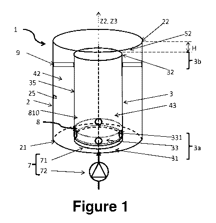
Figure 1 illustrates a photobioreactor 1 according to a first
embodiment.
The photobioreactor 1 comprises a first container 2 which is a first
hollow cylinder extending along a first longitudinal direction Z2 and a second
container 3 which is a second hollow cylinder extending along a second
longitudinal direction Z3 and disposed inside the first hollow cylinder 2. The
two cylinders are cylinders of revolution. The axes of revolution of the first
and second cylinders coincide, in other words, the cylinders are concentric.
Date recu/Date received 2020-06-16
CA 03085888 2020-06-16
The space between the two cylinders forms a first channel 42. The space in
the second cylinder 3 forms a second channel 43.
The first bottom end, or base 21, of the first cylinder 2, closes the
bottom end of the photobioreactor 1.
5 The second bottom end, or base 31, of the second cylinder 3 can
coincide with the base 21 of the first cylinder 2.
The photobioreactor 1 can advantageously comprise means 9 for
fixing the second cylinder 3 and/or positioning it relative to the first
cylinder 2,
for example so that the first channel 42 formed between the two cylinders is
10 of stable form.
The at least one first passage means comprises several first passage
means, or bottom passage means, formed by apertures 331, each aperture
having a substantially circular section, being formed in the wall of the
second
cylinder 3 in the bottom part 3a of said second cylinder. The apertures 331
15 allow a passage between the first channel 42 and the second channel 43.
In the example illustrated, the apertures 331 are formed regularly
along a first circumferential ring 33 of the wall of the second cylinder.
The height difference H between the top ends of the first and second
cylinders defines a second passage means, or top passage means 52.
A fluid can circulate in the photobioreactor 1, notably in the second
channel 43 and in the first channel 42.
In this exemplary embodiment, the injection means 7 comprises
several elements capable of injecting gas in the form of bubbles into the
second channel 43. The injection means 7 comprises a compressor 72 for
sending the gas and a membrane 71 capable of receiving the gas and
injecting it in the form of bubbles. The membrane 71 is disposed inside the
second cylinder 3. The compressor 72 is disposed below the
photobioreactor 1.
The second cylinder 3 and the injection means 7 thus form an air lift
system capable of injecting, into the photobioreactor, a gas, or a mixture of
Date recu/Date received 2020-06-16
CA 03085888 2020-06-16
16
gases, or even a gas/solid mixture, and by so doing, drive the circulation of
the fluid present in the second channel 43.
Depending on the applications, and notably the type of
photobioreactor, the gas/solid mixture can be:
- an air/CO2 gaseous mixture, and/or
- a gaseous mixture comprising solids, notably fine particles, and in
particular microparticles to be treated.
The gas can be town air or industrial fumes, containing pollutants,
including NOR, which can pass in aqueous form (just like CO2) and contribute
to the supply of microalgae.
Hereinafter in the present description, the term gas will be used, it
being understood that it can be a mixture of gases, or a gas/solid mixture.
The fluid is in particular a liquid, more particularly an aqueous solution
comprising microalgae, also called "algal solution". However, the fluid can
also define the mixture between the fluid and the gas, the gaseous mixture or
the gas/solid mixture.
Hereinafter in the present description, the term fluid will be used, it
being understood that it can be either the algal solution alone, or the
mixture
of said algal solution with the gas or with the gaseous mixture, or with the
gas/solid mixture.
The main function of the membrane 71 is to inject the gas in the form
of bubbles and above all more accurately control the size or sizes of said
bubbles, the gas thus being diffused in the second channel 43 in the form of
bubbles, thus making it possible notably to dissolve the gas, for example the
CO2, in the liquid. That can also help to increase the agitation in the
reactor.
As an alternative to a membrane, it can be a diffuser of fine bubbles, a
grating, a porous stone, a hydro-injector or any other means capable of
injecting gas in the form of bubbles and of more accurately controlling the
size or sizes of said bubbles.
Date recu/Date received 2020-06-16
CA 03085888 2020-06-16
17
There can be several membranes and/or other means capable of
injecting gas in the form of bubbles. All are preferably disposed in the
bottom
part 3a of the second cylinder 3, and/or at several levels in said second
cylinder along the longitudinal direction Z3 of said second cylinder.
Figure 5 illustrates the direction of circulation of the fluid. The bubbles
from the injection means 7, and in particular from the membrane 71, rise into
the second channel 43 by driving the fluid present in said second channel.
The duly driven fluid rises inside the second channel 43. Once the top end of
said second channel is reached (corresponding in the example illustrated to
the top end 32 of the second cylinder 3), the fluid pours into the first
channel
42 by crossing the at least one top passage means 52, for example formed
by the space due to a height difference between the first and second
cylinders 2 and 3 at the top ends 22 and 32 of said first and second
cylinders.
Next, the fluid redescends to the bottom end of the first channel 42. At the
bottom end of the first channel 42, the at least one bottom passage means
51, for example apertures 331 in the second cylinder 3, allow the suction of
the fluid descending in the first channel 42 to the second channel 43 by
virtue
of the ascending flow of the second channel, the passage of the fluid once
again into the second channel 43, and once again a fluid driving movement
by the bubbles from the bottom part to the top part of the second channel 43,
when the gas is injected.
The injection means 7 can inject bubbles of gas continually in the
second channel 42.
Alternatively, the injection means 7 can inject bubbles of gas
discontinuously.
Thus, a movement of the fluid is thus created, corresponding to a
forced convection movement in the direction of circulation described above
and illustrated in figure 5.
Date recu/Date received 2020-06-16
CA 03085888 2020-06-16
18
Furthermore, the photobioreactor comprises several light sources 8
represented in figure 1 in the form of several first light columns 810
disposed
on the wall inside the second cylinder 3 and extending along the longitudinal
direction Z3 of said second cylinder. In the example represented, there are
eight light columns 810 disposed regularly on the wall inside the second
cylinder 3.
Other light source dispositions are presented more specifically with
figures 6, 7A, 7B, 8 to 11. All these dispositions can be combined with the
photobioreactor illustrated in figure 1, or with the other embodiments
presented hereinbelow.
Figure 2 illustrates a photobioreactor 1 according to a second
embodiment, which is distinguished from the first embodiment in that it also
comprises at least one recirculation pump 10.
Two recirculation pumps 10 are represented, disposed outside the first
cylinder 2. Said pumps make it possible to accentuate the fluid circulation
flow rate. They are configured so as to suck the fluid from the bottom part of
the photobioreactor, for example in the bottom part of the first channel 42,
and reinject it in the top part of the photobioreactor, for example in the top
part of the first channel 42, accentuating the air lift phenomenon.
The number of pumps and the disposition of the pump or pumps can
be adapted in order to make it possible to accentuate the fluid circulation
flow
rate.
Although all the elements of the photobioreactor have not been
represented in figure 2, it is essential to consider that the photobioreactor
of
the second embodiment can comprise all or some of the elements described
for the first embodiment.
Date recu/Date received 2020-06-16
CA 03085888 2020-06-16
19
Figure 3 illustrates a photobioreactor according to a third embodiment
which is distinguished from the first embodiment in that it comprises at least
one propeller 11.
According to the example represented, the photobioreactor comprises
three propellers 11. One propeller is disposed in the bottom part of the
second channel 43. A propeller is disposed and oriented in such a way that
the propeller can apply an upward movement to the fluid from the bottom end
to the top end of said second channel. Two other propellers are disposed in
the first channel 42 so as to apply a downward movement to the fluid in said
first channel from the top end to the bottom end of said first channel.
The propellers, driven by a motor disposed outside the
photobioreactor 1, rotate and stir the fluid inside the photobioreactor. The
propellers create a stirring which makes it possible to accentuate the
stirring
of the fluid in the photobioreactor.
The number of propellers and the disposition of the propeller or
propellers in the photobioreactor can be adapted in order to obtain the same
effect.
Although all the elements of the photobioreactor have not been
represented in figure 3, it is essential to consider that the photobioreactor
of
the third embodiment can comprise all or some of the elements described for
the first embodiment.
Figures 4A and 4B show an example of a photobioreactor according to
a fourth embodiment.
Figure 4A illustrates a photobioreactor 1 comprising a first cylinder 2 of
revolution of first outer diameter D2 extending along a first longitudinal
direction Z2 over a first height H2 and a second cylinder 3 of revolution of
second outer diameter D3 extending along a second longitudinal direction Z3
over a second height H3. The two cylinders are hollow cylinders of revolution
and are concentric.
Date recu/Date received 2020-06-16
CA 03085888 2020-06-16
The space between the two cylinders forms a first channel 42. The first
channel 42 has a cylindrical sleeve form of a height equal to the height H3 of
the second cylinder 3 and whose width corresponds to (D2-D3)/2 (and to
(D2-D31)/2 at the level of the base 31 of the second cylinder, as explained
5 hereinbelow).
The height H between the two cylinders forming a second passage
means 52 is equal to H2-H3.
The photobioreactor 1 comprises holding means 9 capable of
positioning and/or holding the second cylinder 3 relative to the first
cylinder 2.
10 As an example, and as illustrated, the holding means 9 comprise
holding cleats 91 disposed at the level of the top part 3b, preferably at the
level of the top end 32 of the second cylinder 3, and capable of positioning
the second cylinder 3 relative to the first cylinder 2.
Furthermore, they comprise centering cleats 92 fixed to the base 21 of
15 the first cylinder 2 and capable of centering the second cylinder 3
relative to
the first cylinder 2.
The lateral wall of the first cylinder 2 is made of transparent PVC, and
its thickness is for example 10 mm.
The base 21 of the first cylinder 2 is made of non-transparent PVC and
20 its thickness is for example 10 mm.
The base 21 of the first cylinder 2 is passed through by two passages
26, for example tappings, allowing a fluid or a fluid/solid mixture to arrive
and/or leave inside said first cylinder.
The second cylinder 3 is disposed on the base 21 of the first cylinder
2, and is centered relative to said first cylinder by virtue of the centering
cleats 92.
The base 31 of the second cylinder has a diameter D31 greater than
the diameter D3 and comprises a bottom end in the form of notches 311, of
which the protruding parts 311b are in contact with the base 21 of the first
cylinder. The height of the bottom end is equal to H31. Each depression of a
notch 311a can have a length L311a and a height H311a.
Date recu/Date received 2020-06-16
CA 03085888 2020-06-16
21
The depressions 311a of the notches can form first passage means for
the fluid.
The injection means 7 comprises several elements capable of injecting
gas in the form of bubbles into the second channel 43.
In this exemplary embodiment, the injection means 7 comprises a
compressor 72 for sending the gas and a membrane 71 capable of receiving
the gas and injecting it in the form of bubbles and diffusing it in the second
channel 43. The compressor 72 is disposed below the photobioreactor 1.
The membrane 71 is disposed in the base 31 of the second cylinder 3.
It takes the form of a flat disk of diameter D71.
Figure 4B illustrates more specifically the second cylinder of
revolution 3.
The lateral wall of the second cylinder 3 is made of transparent PVC,
and its thickness is for example 5 mm.
The second cylinder 3 also comprises first passage means in the form:
- of first apertures 331 of diameters D331, disposed and distributed
regularly along a first circumferential ring 33 in the wall of the second
cylinder, at a height equal to H33 relative to the point of contact of the
base
31 of said second cylinder with the base 21 of the first cylinder, and
- of second apertures 331' of diameters D331', disposed and
distributed regularly along a second circumferential ring 33' in the wall of
the
second cylinder, at a height equal to H33' relative to the point of contact of
the base 31 of said second cylinder with the base 21 of the first cylinder.
As an example, the abovementioned dimensions can be:
- D2 = 400 mm
- H2 = 3000 mm
- D3 = 200 mm
- H3 = 2525 mm
- H = H2-H3 = 475 mm
Date recu/Date received 2020-06-16
CA 03085888 2020-06-16
22
- D31 = 280 mm
- H31 = 50 mm
- D331 = D331' = 30 mm
- H33 = 100 mm
- H33' = 200 mm
- L311a = 75 mm
- H311a = 22 mm
- D71 = 270 mm
Furthermore, the photobioreactor comprises several light sources 8
represented in the form of columns or tubes 810 in figures 4A and 4B, but
which can be configured otherwise, as presented hereinbelow.
Several light sources 8 can create a uniform light array by being
spaced apart from one another by 10 cm.
According to an embodiment that is not represented, that can notably
be applied to all the preceding embodiments, there can be several second
containers 3 inside the first container 2. In this case, there can be several
second channels 43.
That makes it possible to improve the uniformity of diffusion of the light
within the algal liquid, increase the fluid circulation flow rate (reduction
of the
sections) and thus improve the homogenization of the medium, prolong the
dwell time of the CO2 bubbles in the medium and thus improve the rate of
dissolution of CO2 in the medium.
As indicated above, figures 6, 7A, 7B, 8, 9, 10, 11 illustrate several
light source dispositions.
The light sources are preferably distanced apart from one another by a
maximum of 10 cm.
In the examples illustrated, the first container 2 is represented as
being a cylinder of revolution, of longitudinal direction Z2 and the second
Date recu/Date received 2020-06-16
CA 03085888 2020-06-16
23
container 3 is represented as being a cylinder of revolution, of longitudinal
direction Z3.
To simplify the reading, in figures 6, 7A, 7B, 8, 9, 10, 11, cylinders of
revolution are represented and the corresponding description expresses first
and second cylinders, it being understood that they can be containers which
are not necessarily cylinders, and notably not necessarily cylinders of
revolution.
The various light source dispositions can be combined with one
another.
Furthermore, they can be combined with each of the different
embodiments presented in conjunction with figures 1 to 4B.
The lighting is preferably produced by LEDs, but other light sources
can be envisaged. They can be spots, or festoons or light strips. Other
embodiments are presented herein below.
The bubbles themselves can be light sources because they can
diffract the light and return it to the fluid.
The intensity of the light sources must be appropriate: an excessively
strong intensity risks roasting the micro-algae, and, on the other hand, an
excessively low intensity makes them stick to the walls of the reactor.
Figure 6 illustrates a first example in which the light sources 8
comprise first light sources 81 disposed inside the second cylinder 3.
They are illustrated in the form of first light columns 810 extending
along the longitudinal direction Z3 of the second cylinder 3.
The first light columns 810 are positioned on the internal lateral
surface of said second cylinder, and are distributed regularly. In this
example,
eight light columns 810 are represented, but there can be fewer, or more.
The first light columns 810 can be fixed to a wall of the second
cylinder 3, for example by a snap-fitting system.
Date recu/Date received 2020-06-16
CA 03085888 2020-06-16
24
In a photobioreactor in which the cylindrical walls are opaque, notably
those of the second cylinder, it is important for the light sources to be able
to
diffuse the light at 3600 and therefore for them not to be stuck to the walls
of
the cylinders.
Thus, alternatively or in addition, the first light columns 810 can be
positioned inside the second cylinder 3, but not on a lateral surface of said
cylinder, as illustrated in figures 7A (3D view) and 7B (plan view): second
example of placement.
The spacing of the first light columns 810, and more broadly the
spacing of the first light sources 81, with the internal lateral surface of
the
second cylinder 3, depends on the turbidity of the medium, on the
concentration of algae, but also on the light intensity delivered.
Alternatively or in addition, second light columns 820 can be
positioned between the first cylinder and the second cylinder, on the external
lateral surface of the second cylinder 3 as illustrated in figure 8 in plan
view
(third example of placement).
Alternatively or in addition, second light sources 820 can be positioned
between the first cylinder and the second cylinder, but not necessarily on the
external lateral surface of the second cylinder.
Figure 9 illustrates a fourth example of placement of light sources 8, in
plan view.
In this example, first light sources 81 are disposed inside the second
cylinder 3 and third light sources 83 are disposed outside the first cylinder
2.
The first light sources 81 are in the form of light columns 810 disposed
inside the second cylinder 3.
The first light columns 810 extend along the longitudinal direction Z3
and are positioned at a given distance from the internal lateral surface of
the
second cylinder 3. They can alternatively be disposed according to one of the
Date recu/Date received 2020-06-16
CA 03085888 2020-06-16
first and third examples presented, or according to a combination of the first
to third examples of placement.
The third light sources 83 are in the form of several second light
columns 830 extending along the longitudinal direction Z2 of the first
cylinder
5 .. 2. They can be positioned against the wall of the first cylinder 2 or at
a
distance D83 from the first cylinder 2.
The distance D83 between the third light columns 830 and the
external lateral surface of the first cylinder 2, and more broadly between the
third light sources 83 and said wall, depends on the turbidity of the medium,
10 on the concentration of algae, but also on the light intensity
delivered.
Figure 10 illustrates a fifth example of placement of light sources.
In this example also, second light sources 82 are disposed outside the
second cylinder 3 and third light sources 83 are disposed outside the first
15 cylinder 2.
As in the preceding example, the third light sources 83 are in the form
of third light columns 830 extending along the longitudinal direction Z2 of
the
first cylinder 2. They can be positioned against the external lateral surface
of
the first cylinder 2 or at a distance D83 from the first cylinder 2.
20 Alternatively, the third light sources 83 may not be incorporated.
The second light sources 82 comprise a second light coil 821 forming
a helix whose axis corresponds to the longitudinal direction Z3 of the second
cylinder 3, disposed around the external lateral surface of said second
cylinder.
25 Alternatively or in addition, a first light coil can be disposed inside
the
second cylinder 3.
Alternatively or in addition, a third light coil can be disposed outside
the first cylinder 2.
The second, respectively first, light coil can be positioned on the
external, respectively internal, lateral surface of said second cylinder or
positioned at a given distance from said lateral surface.
Date recu/Date received 2020-06-16
CA 03085888 2020-06-16
26
The third light coil can be positioned on the external lateral surface of
the first cylinder or positioned at a given distance from said lateral
surface.
Figure 11 illustrates a sixth example of placement of light sources,
which differs from the fifth example in that the third light sources 83
comprise
light bar segments 832 extending along the longitudinal direction Z2 of the
first cylinder 2 and positioned outside said first cylinder.
The third light sources 83 can be positioned against the wall on the
outside of the first cylinder 2 or at a distance D83 from the first cylinder
2.
The various embodiments presented can be combined with one
another.
Furthermore, the present invention is not limited to the embodiments
previously described but extends to any embodiment falling within the scope
of the claims.
Date recu/Date received 2020-06-16