Note: Descriptions are shown in the official language in which they were submitted.
CA 03086803 2020-06-23
WO 2019/150218 PCT/IB2019/050441
1
REFRACTIVE TREATMENT OF AN EYE BY PRINTING
MATERIAL ONTO A TARGET
TECHNICAL FIELD
The present disclosure relates generally to refractive treatment of an eye,
and more
specifically to refractive treatment of an eye by printing material onto a
target.
BACKGROUND
Refractive treatment of an eye refers to surgery performed to change the
refractive
properties of the eye to reduce refractive error in order to improve vision.
Refractive error
occurs when the shape of the eye does not bend light correctly, resulting in a
blurred image.
The main types of refractive errors are myopia (nearsightedness), hyperopia
(farsightedness),
presbyopia (loss of near vision with age), and astigmatism. Typical refractive
treatments
include laser in-situ keratomileusis (LAS 1K), photorefractive keratectomy
(PRK), radial
keratotomy (RK), astigmatic keratotomy (AK), automated lamellar keratoplasty
(ALK), laser
thermal keratoplasty (LTK), conductive keratoplasty (CK), and intracorneal
ring (Intacs).
BRIEF SUMMARY
In certain embodiments, a system for performing refractive treatment of an eye
comprises a laser, a printer, and a computer. The laser emits a laser beam to
prepare the eye for
the refractive treatment. The printer prints material onto a print area of a
target. The printer
comprises a printer head and a printer controller. The printer head directs
the material onto the
print area, and the printer controller moves the printer head to direct the
material onto a specific
location of the print area. The computer comprises a memory and processors.
The memory
stores instructions for a pattern for the target. The pattern is designed to
provide the refractive
treatment for the eye. The processors instruct the printer controller to move
the printer head to
print the material onto the print area according to the pattern.
In certain embodiments, a method for performing refractive treatment of an eye
comprises emitting, from a laser, a laser beam to prepare the eye for the
refractive treatment.
A computer communicates with a printer configured to print material onto a
print area of a
target, where the printer comprises a printer head that directs the material
onto the print area
CA 03086803 2020-06-23
WO 2019/150218 PCT/IB2019/050441
2
and a printer controller that moves the printer head to direct the material
onto a specific location
of the print area. The computer accesses instructions for a pattern for the
target, where the
pattern is designed to provide the refractive treatment for the eye. The
computer instructs the
printer controller to move the printer head to print material onto the print
area according to the
pattern.
BRIEF DESCRIPTION OF THE DRAWINGS
Embodiments of the present disclosure are described by way of example in
greater
detail with reference to the attached figures, in which:
FIGURE 1 illustrates an example of a system for refractive treatment of an
eye;
FIGURE 2 illustrates an example of a method for refractive treatment of an
eye;
FIGURE 3 illustrates an example of an implant created by the system of FIGURE
1 for
correction of hyperopia;
FIGURE 4 illustrates an example of material deposited by the system of FIGURE
1 for
correction of hyperopia;
FIGURE 5 illustrates an example of material deposited by the system of FIGURE
1 for
correction of astigmatism and/or improvement of biomechanical stability; and
FIGURE 6 illustrates an example of material deposited by the system of FIGURE
1 for
correction of myopia.
CA 03086803 2020-06-23
WO 2019/150218
PCT/IB2019/050441
3
DESCRIPTION OF EXAMPLE EMBODIMENTS
Referring now to the description and drawings, example embodiments of the
disclosed
apparatuses, systems, and methods are shown in detail. As apparent to a person
of ordinary
skill in the field, the disclosed embodiments are exemplary and not exhaustive
of all possible
embodiments.
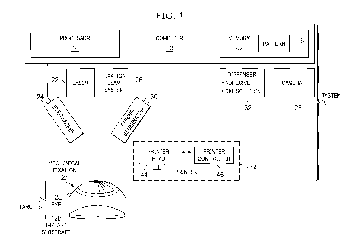
FIGURE 1 illustrates an example of a system 10 for refractive treatment of an
eye 12a.
System 10 includes a printer 14 that prints material (e.g., biological or
biocompatible material)
onto a print area of a target 12 according to a pattern 16 designed to provide
refractive treatment
for eye 12a. In some cases, target 12 may be eye 12a, and printer 14 prints
the material directly
onto eye 12a to perform the refractive treatment. In other cases, target 12
may be an implant
substrate 12b. When implant substrate 12b is printed with the material, it
yields an implant to
be implanted into eye 12a for the refractive treatment.
In the illustrated embodiment, system 10 comprises a computer 20, printer 14,
a laser
22, an eye-tracker 24, a fixation beam system 26, a mechanical fixation 27, a
camera 28, a
curing illuminator 30, and a dispenser 32. Computer 20 includes one or more
processors 40
one or more memories 42 that stores pattern 16. Printer 14 includes a printer
head 44 and a
printer controller 46.
As an overview, in certain embodiments, computer 20 controls the components of
system 10. Laser 22 prepares eye 12a for refractive treatment by, e.g.,
exposing an area of the
cornea of eye 12a to be printed or making an incision within the cornea to
receive an implant.
Memory 42 stores pattern 16 designed to provide refractive treatment for eye
12a. Printer 14
prints material onto target 12 according to pattern 16. Fixation beam system
26 and/or
mechanical fixation 27 stabilizes target 12 to reduce movement of target 12.
Eye-tracker 24
tracks movement of target 12 and sends information describing the movement to
computer 20,
which in response can instruct printer 14 to compensate for the movement.
Curing illuminator
illuminates the printed material with a light that promotes curing of the
material. Dispenser
32 dispenses an adhesive that promotes adhesion of the material to target 12
and/or a cross-
linking solution that promotes cross-linking within the cornea. Camera 28
generates images of
30 the treatment to assist with monitoring the treatment.
System 10 provides refractive treatment for eye 12a. Refractive treatment
involves a
procedure that changes the refractive properties of eye 12a to improve vision.
Pattern 16
indicates where material should be printed on a print area of target 12 in
order to yield a result
CA 03086803 2020-06-23
WO 2019/150218
PCT/IB2019/050441
4
(e.g., a resulting corneal shape) that improves vision. For example, pattern
16 may indicate
where material should be printed on a print area of eye 12a such that, after
eye 12a recovers
from the procedure, the printed material yields a shape for eye 12a that
improves the vision of
eye 12a. As another example, pattern 16 may indicate where material should be
printed on a
print area of an implant substrate 12b to yield an implant such that, after
eye 12a recovers from
the implantation procedure, the implant improves the vision of eye 12a.
Examples of pattern
16 are illustrated in FIGURES 3 to 6.
In some embodiments, target 12 is an eye 12a, such as an eye of a human or
other
animal. In other embodiments, target 12 is an implant substrate 12b for an
ocular implant. An
ocular implant is an artificial aid surgically implanted into eye 12a to
improve vision. Implant
substrate 12b is a substrate onto which material may be printed to form an
implant. Implant
substrate 12b may comprise any suitable transparent biocompatible material,
e.g., hyaluronan
(also called hyaluronic acid) or collagen. Implant substrate 12b may have any
suitable size or
shape. For example implant substrate 12b may be circular or annular with a
diameter in the
range of 0.5 to 12 millimeters (mm), or in a sub-range such as 0.5 to 5 mm, 5
mm to 8 mm,
and/or 8 to 12 mm. The print area of target 12 may be the area onto which
material is printed.
To aid in description, this description uses a coordinate system commonly used
in
ophthalmological surgery. In this coordinate system, a laser beam operating on
the eye defines
the z-axis, and the xy-plane is the plane normal to the z-axis. Generally, the
xy-plane coincides
with the plane defined by the pupil, apex, or vertex of the eye.
Fixation beam system 26 and/or mechanical fixation 27 stabilizes target 12 to
reduce
movement of target 12. Fixation beam system 26 provides a fixation beam onto
which the
patient fixes their gaze to avoid moving eye 12a. Mechanical fixation 27 is
affixed to eye 12a
to reduce or prevent movement of eye 12a. Examples of mechanical fixation 27
include patient
interfaces such as corneal suction rings.
Laser 22 prepares eye 12a for refractive treatment. Laser 22 may be any
suitable laser
surgical device that generates and emits a laser beam that interacts with
(e.g., photodisrupt or
photoablate) the cornea of eye 12a. A laser surgical device typically
comprises laser source
(e.g., femto or excimer) that generates a laser beam, and scanning components
(e.g., optics)
that direct the focus of the laser beam to specific points of the target.
Laser 22 prepares eye 12a
for treatment by interacting with the cornea in any suitable manner. For
example, laser 22 may
expose the print area of the cornea of eye 12a by creating a flap in the
cornea or removing all
or part of an epithelium of eye 12a (e.g. phototherapeutic keratectomy (PTK)).
As another
CA 03086803 2020-06-23
WO 2019/150218
PCT/IB2019/050441
example, laser 22 may make an incision (e.g., a pocket) within the cornea to
receive an implant.
As another example, laser 22 may perform subsequent steps of the treatment.
For instance,
laser 22 may shape the cornea or printed material to yield prescribed
refractive properties or
perform other actions to complete the treatment. In certain embodiments, laser
22 may
5 incorporate different laser sources that generate different laser beams,
e.g., laser 22 may have
sources that generate a beam that photodisrupts the corneal or printed
material and a beam that
ablates the corneal or printed material.
Printer 14 prints material onto the print area of target 12, and may comprise
any suitable
printer configured to deposit material onto a print area according to digital
instructions. For
.. example, printer 14 may be a 3D, or additive manufacturing, printer that
deposits successive
layers of material to yield the material configured in a specific shape and
size. Printer 14
includes printer head 44 and printer controller 46. Printer head 44 directs
material onto the print
area and may be any suitable printer extruder that deposits material onto a
surface. Printer
controller 46 moves the printer head in the x, y, z directions to direct the
material onto a specific
location of the print area, and may receive instructions from computer 20 to
move the printer
head 44 according to pattern 16.
The material comprises any suitable transparent or semitransparent material
that is
biological and/or biocompatible. Examples of such material include cultivated
collagen
material, human or animal cell material, biocompatible plastic, or hyaluronan.
In certain cases,
a material over which the epithelium can grow may be used. Such material may
provide optimal
nutrition of corneal cells and extra-cellular material, optical transparency
over lifetime, and
supportive surface properties for epithelium growth.
Eye-tracker 24 tracks movement of target 12 to aid in accurately printing the
material
on target 12. Eye-tracker 24 may track eye 12a, as a target eye 12a is more
likely to move and
need tracking than a target implant substrate 12b. However, eye-tracker 24 may
be used to
track any type of target 12. An eye-tracker detects translational and/or
angular (or rotational)
movement of eye 12a. In certain embodiments, image processing is used to
locate the central
point of eye 12a, e.g., the pupil, determine translational movement. Image
processing is used
to locate features of eye 12a (e.g., blood vessels, iris features, or any
other appropriate feature)
to determine angular movement.
When eye-tracker 24 detects movement of target 12, eye-tracker 24 notifies
computer
20, which adjusts the instruction to printer controller 46 to compensate for
the movement of
target 12. For example, if target 12 is translates and/or rotates a certain
amount, printer
CA 03086803 2020-06-23
WO 2019/150218 PCT/IB2019/050441
6
controller 46 compensates for the movement by translating and/or rotating
pattern 16 that
certain amount.
In other embodiments, an interface may fix or hold target 12 in a desired
location and
position such that eye-tracker 24 may not be required. For example, a patient
interface may
hold eye 12a in place using, e.g., suction.
Curing illuminator 30 illuminates the print area with a light that cures the
material. The
light may cure the material by promoting cross-linking of the material and
optionally the cornea
of the eye. Examples of curing light include ultraviolet light or light (such
as LED light)
between 400 to 500 nm.
Dispenser 32 deposits a liquid onto target 12 during the procedure. For
example,
dispenser 32 directs onto eye 12a a corneal cross-linking solution that
promotes cross-linking
of the cornea of eye 12a. Examples of a corneal cross-linking solution include
a riboflavin
solution or other suitable solution. As another example, dispenser 32 directs
onto the print area
an adhesive that promotes adhesion of the material onto the print area. An
adhesive may include
fibrin.
Camera 28 generates an image of the print area to monitor the printing of the
material.
Camera 28 may comprise any suitable system that can generate an image of an
object.
Examples of camera 28 include an OCT system (such as a time domain or
frequency domain
OCT system) that generates OCT scans that can be used to create the image of
the print area.
FIGURE 2 illustrates an example of a method for refractive treatment of an eye
12a by
printing material on a target 12, which may be performed by system 10 of
FIGURE 1. The
method starts at step 110, where laser 22 prepares eye 12a for refractive
treatment. Depending
on the procedure, laser 22 may: create a flap in the cornea of eye 12a to
prepare for a LASIK
procedure; create a pocket in the cornea designed to receive a corneal
implant; or remove the
epithelium of eye 12a to prepare for a PRK procedure.
Print area of target 12 is prepared at step 112. Target 12 may be eye 12a
itself or an
implant substrate 12b for an implant to be implanted into eye 12a. The print
area may be
prepared in any suitable manner. For example, dispenser 32 may direct an
adhesive onto the
print area that promotes adhesion of the material onto the print area. Camera
28 generates an
image (such as a OCT scan image) of the print area at step 114 to monitor the
printing of the
material.
At step 116, printer 14 prints material onto the print area according to
pattern 16
designed to provide refractive treatment for eye 12a. The material may be
transparent material
CA 03086803 2020-06-23
WO 2019/150218 PCT/IB2019/050441
7
that is biological and/or biocompatible. Note, if target 12 is implant
substrate 12b, step 116
may be performed prior to the procedure, such that step 116 occurs before step
110.
Eye-tracker 24 tracks movement of target 12 at step 117. Movement may be
detected
at step 118. If movement is detected, computer 20 receives information
describing a movement
.. of target 12 and instructs printer 14 to compensate for the movement. The
method then moves
to step 122. If no movement is detected, method moves directly to step 122. In
embodiments
that use a patient interface to fix target 12 into position, the method
typically does not perform
steps 117, 118, and 122.
Curing illuminator illuminates the print area at step 122 with a light that
cures the
material. Step 124 depends on the procedure and whether target 12 is eye 12a
or implant
substrate 12b. If target 12 is implant substrate 12b, the method moves to step
126, where the
implant is inserted into eye 12a. The method then moves to step 128. If target
12 is eye 12a,
the method moves directly to step 128.
At step 128, dispenser 32 directs a corneal cross-linking solution onto eye
12a that
promotes cross-linking of the cornea. The procedure is completed at step 130,
which depends
on the procedure. For example, in a LASIK procedure, completing the procedure
may involve
closing the flap. The method then ends. After the method ends, the healing
processes begin.
For example, if the method removes the epithelium, it re-grows over the
printed implant.
FIGURES 3 to 6 illustrate implants and deposited material that may be created
using
patterns 16 that guide the creation of the 3D shapes. A pattern 16 may be
stored as a 3D
printable file, such as the STL file format native to the stereolithography
CAD software created
by 3D Systems.
FIGURE 3 illustrates an example of an implant 54 created by system 10 for
correction
of hyperopia. In the example, eye 12a has a cornea 50 and an epithelium 52.
Implant 54 may
.. have a shape similar to that of a contact lens, and is inserted into a
pocket 56 of cornea 50.
FIGURE 4 illustrates an example of material 60 deposited by system 10 for
correction
of hyperopia. In the example, part of epithelium 52 is removed. System 10
deposits material
60 onto the exposed stroma of cornea 50 in a shape that corrects hyperopia.
Deposited material
60 may have the shape of a thin layer disposed on the stroma. Epithelium 52
grows over
material 60.
FIGURE 5 illustrates an example of material 60 deposited by system 10 for
correction
of astigmatism and/or improvement of biomechanical stability (e.g.,
keratoconus). In the
example, part of epithelium 52 is removed. System 10 deposits material 60 onto
the exposed
CA 03086803 2020-06-23
WO 2019/150218
PCT/IB2019/050441
8
stroma of cornea 50 in a shape that corrects astigmatism and/or improves
biomechanical
stability. Deposited material 60 may have the shape of a dome disposed on the
stroma.
Epithelium 52 grows over material 60.
FIGURE 6 illustrates an example of material 60 deposited by system 10 for
correction
of myopia. In the example, part of epithelium 52 is removed. System 10
deposits material 60
onto the exposed stroma of cornea 50 in a shape that corrects myopia.
Deposited material 60
may have the shape of an annular ring disposed on the stroma. Epithelium 52
grows over
material 60.
A component (e.g., a computer) of the systems and apparatuses disclosed herein
may
include an interface, logic, and/or memory, any of which may include hardware
and/or
software. An interface can receive input to the component, provide output from
the component,
and/or process the input and/or output. Logic can perform the operations of
the component,
e.g., execute instructions to generate output from input. Logic may be a
processor, such as one
or more computers or one or more microprocessors. Logic may be computer-
executable
instructions encoded in memory that can be executed by a computer, such as a
computer
program or software. A memory can store information and may comprise one or
more tangible,
non-transitory, computer-readable, computer-executable storage media. Examples
of memory
include computer memory (e.g., Random Access Memory (RAM) or Read Only Memory
(ROM)), mass storage media (e.g., a hard disk), removable storage media (e.g.,
a Compact
Disk (CD) or a Digital Video Disk (DVD)), and network storage (e.g., a server
or database).
Although this disclosure has been described in terms of certain embodiments,
modifications (such as substitutions, additions, alterations, or omissions) of
the embodiments
will be apparent to those skilled in the art. Accordingly, modifications may
be made to the
embodiments without departing from the scope of the invention. For example,
modifications
may be made to the systems and apparatuses disclosed herein. The components of
the systems
and apparatuses may be integrated or separated, and the operations of the
systems and
apparatuses may be performed by more, fewer, or other components. As another
example,
modifications may be made to the methods disclosed herein. The methods may
include more,
fewer, or other steps, and the steps may be performed in any suitable order.