Note: Descriptions are shown in the official language in which they were submitted.
CA 03087380 2020-06-29
WO 2019/133276
PCT/US2018/065452
APPARATUS FOR REDUCING DRAG OF A TRANSVERSE DUCT EXIT FLOW
CROSS-REFERENCE TO RELATED APPLICATION
(001] This patent application claims priority to US provisional Application
number
62/611,143, filed December 28, 2017, the content of which is incorporated by
reference herein
in its entirety.
FIELD OF INVENTION
[002] The invention relates to aircraft fairings, and more specifically to a
fairing assembly
positioned about a duct outlet port of an aircraft or other vehicle.
BACKGROUND OF INVENTION
[003] Fluid duct outlet ports on aircraft and other types of vehicles are
often subject to
design compromises which prevent their orientation parallel, or nearly
parallel to a surface
from which they are formed. A nearly parallel orientation is optimum, as
illustratively shown
by distributed propulsion jets in US patent no. 6,767,261. More specifically,
when the fluid
duct outlet ports are close to having parallel orientation with respect to the
surface from which
they extend, thrust is maximized while drag is minimized by energizing fluid
surface flow
with the duct flow, or by allowing low velocity duct flow to mix with high
velocity surface
flow with minimum drag.
[004] Fluid ducts that are not directly used for propulsion can include
cooling, exhaust,
waste effluent, and other well-known fluid outlets. When the fluid duct outlet
is oriented
within ten degrees with respect to the surface fluid flow, the additional drag
of the duct flow is
minimal and mainly independent of the ratio of duct outlet flow to surface
fluid flow
velocities. This ratio is known as the "relative velocity" of the duct.
However, vehicle
structural or other considerations often force duct outlets to be oriented at
higher angles with
respect to the surface flow.
[005] For duct outlet angles generally exceeding ten degrees, a high relative
duct fluid
velocity versus surface fluid velocity will lead to the duct flow departing
the surface of the
aircraft and disrupting the flow in front of, around, and behind the duct
outlet. This causes
recirculation of the surface and duct flows, which often leads to fluid
dynamic drag and noise.
.1
CA 03087380 2020-06-29
WO 2019/133276 PCT/US2018/065452
[006] To turn the angled duct outlet flow along a surface that is not parallel
to the duct, a
variety of prior art devices have been used with varying results. Duct
relative velocity may
vary widely over different operating conditions. Accordingly, it is desirable
that any such
device should be effective where a high duct relative velocity and a high duct
outlet angle
occurs, while also having minimal impact on the surface flow drag at low duct
relative
velocity.
[007] As well, angled ducts with propulsion effects can also trade off drag
for the
mechanical simplicity of a higher than optimum duct angle, where thrust would
be decreased
while drag and noise would be increased. Accordingly, it is desirable to
provide a simple way
of turning the propulsion duct flow parallel with the surface flow that
decreases duct
restriction, increases thrust, and reduces drag and noise.
[008] The use of the Coanda effect to turn airflow has been in wide use for
many years. The
Coanda effect allows a fluid flow to follow a curved surface, such as on the
flaps of a wing, as
illustratively disclosed in US patent no. 4,447,028. A fairing implementing
the Coanda effect
may be placed immediately downstream of a highly angled outlet duct. A Coanda
fairing may
be successfully used on slightly angled ducts with high duct relative
velocities and at greater
angles if the duct relative velocity is low. Turning a highly angled flow at
high relative
velocity from an outlet duct with only a Coanda fairing is not possible in
less than dime duct
diameters of length and a profile height of less than one-half (0.5) of a duct
diameter. To be
effective, the leading edge of the Coanda fairing is parallel to the duct
outlet and turns to
attach the duct flow to the surface at less than a 15 degree angle to the
surface,
[009] The use of vortex generators to circulate organized flow to reduce or
eliminate areas of
recirculation is also well-known in the art for controlling a flow of a fluid.
Highly angled
fluid flow from a duct outlet creates large areas of recirculation that
generally requires very
large vortex generators to organize the flow. Such large vortex generators can
induce
significant drag and noise, thereby negating the benefits of organizing the
recirculation.
(0010) Referring now to the prior art drawings of FIGS. 1-3, air turbulence is
illustratively
shown about and within an angled outlet duct port at the surface of an
aircraft. The aircraft 10
includes a high angled duct 20 (e.g., greater than 10 degrees) having a duct
outlet port 22
formed at an exterior surface 12 of the aircraft 10 and the angled duct 20
intersects and
terminating at the exterior surface 12 at an outlet port 22. In the prior art
FIGS. 1-3, the fore
and aft ends of the aircraft are on the left and right sides of the drawing,
respectively.
CA 03087380 2020-06-29
WO 2019/133276
PCT/US2018/065452
Accordingly, the aircraft flies towards the left and the air flowing at the
surface of the aircraft
is in a direction of left to right, as illustratively shown by arrow "A" in
FIG. 3, where the duct
20 and outlet 22 are illustratively shown on a bottom portion of the
aircraft). The duct 20 is
angled from the forward to aft direction to help minimize the turbulence of
fluid from the duct
outlet port when combining with the surface air flow. The angling (e.g., forty
degrees) of the
duct 20 and its outlet port 22 are a matter of design choice that is often
determined by nearby
or adjacently positioned structures of the aircraft.
[0011]For example, the duct conduit 20 which terminates at the outlet port 22
can often have
protuberances, bends, obstructions, and other structural restrictions 30
therein which can
cause significant fluid flow disturbances 32 in the duct flow. Some of these
structural
restrictions 30 can create fluid recirculation 32 within the duct 20, which
often leads to back
pressure and restriction of the duct flow. It has also been observed that the
greater the angle
of the duct outlet 22 to the corresponding vehicle surface 12, the more
recirculation 32 in the
duct 20 will be caused by the surface flow, thereby leading to greater duct
flow restriction.
[0012] To address the undesirable recirculation effect, it is known to install
a series of angled
vanes at the duct outlet 22 to organize the fluid flow and steer it towards
the surface axis.
However, the angled vanes can also cause duct flow restriction, as well as
surface drag when
the duct has minimal or no fluid flow. If the duct outlet 22 has originally
been designed
without vanes, the additional restriction of adding vanes can compromise the
performance of
any fluid flow system that depends on the as-designed duct efficiency.
Therefore, there is a
need to better control fluid flow from and at the surface boundary layer of
many common
outlet ducts 22.
(0013] US patent no. 3,525,486 discloses a placement of a vortex generator
inside a duct to
assist with turning the flow to the surface axis. This creates unacceptable
restriction to the
duct flow for many applications.
[0014] In view of the aforementioned and other deficiencies in the prior art,
it is desirable to
provide a fluid flow duct outlet apparatus such as an assembly of fairings and
vanes about an
existing duct outlet port and its surrounding surface areas, which creates an
effect not possible
by the use of these devices individually.
SUMMARY OF THE INVENTION
3
CA 03087380 2020-06-29
WO 2019/133276
PCT/US2018/065452
[0015] The above disadvantages and deficiencies in the prior art are avoided
and/or solved by
various embodiments of an angled duct outlet fairing assembly for reducing
drag of a duct
outlet port of an angled duct in an aircraft or other vehicle comprising: a
vane fairing having a
upwardly sloped ramp portion that includes a leading edge mounted forward a
leading edge of
the duct outlet port, the ramp portion extending rearwardly and upwardly over
a portion of the
duct outlet port, the ramp being aligned in a direction of a longitudinal axis
of the vehicle; a
Coanda fairing having an elongated body with a leading edge circumscribing a
trailing edge
of the duct outlet port, the elongated body having a predetermined height,
width and
extending rearwardly a predetermined length based on a dimension of the duct
outlet port; and
a pair of vortex generators positioned rearwardly of the duct outlet port,
each vortex generator
being positioned on an opposing lateral side of the Coanda fairing and angled
towards each
other.
[0016] in one embodiment, the ramp portion of the vane fairing has a curved
upper surface to
direct surface air flow along an exterior surface of the aircraft at an
upwardly sloped angle
away from the duct outlet port. In another aspect, the ramp portion of the
vane fairing has a
curved lower surface to direct or turn duct fluid flow exiting the duct outlet
port in a direction
towards the Coanda fairing. In yet another aspect, the ramp portion of the
vane fairing has a
predetermined length based on the dimension of the duct outlet port. in still
another aspect,
the ramp portion has a length as measured between its leading edge and
trailing edge of 0.5 to
0.9 diameters of the duct outlet port. In a further aspect, the ramp portion
of the vane fairing
has a predetermined height as measured from the surface of the aircraft based
on one-half of
duct angle and the length of the ramp portion.
[0017] In another embodiment, the ramp further includes a tongue portion that
extends
downwardly into the angled duct. In one aspect, the tongue portion is
configured to and
extends a distance that is sufficient to cover a structural obstruction within
the angled duet.
[0018] In still another embodiment, the Coanda fairing is substantially
triangular in shape. In
one aspect, the Coanda fairing has a height in a range of 0.15 to 0.25
diameters of the duct
outlet port per forty-five degrees of duct angle. In another aspect, the
Coanda fairing has a
height of 0.2 diameters of the duct outlet port per forty-five degrees of duct
angle. In yet
another aspect, the Coanda fairing has a length in a range of 1.5 to 3.0
diameters of the duct
outlet port per forty-five degrees of duct angle. In another aspect, the
Coanda fairing has a
length of 3.0 diameters of the duct outlet port per forty-five degrees of duct
angle.
4
CA 03087380 2020-06-29
WO 2019/133276
PCT/US2018/065452
[0019] In yet another embodiment, each of the pair of vortex generators
extends substantially
perpendicular from an exterior surface of the vehicle. In one aspect, the pair
of vortex
generators are positioned aft of the duct within two duct diameters. In
another aspect, each of
the pair of vortex generators are angled between fifteen and thirty degrees to
a centerline of
the duct outlet port to thereby generate counter rotating vortices which
converge behind the
Coanda fairing. In still another aspect, each of the pair of vortex generators
includes a base
which is mounted to an exterior surface of the vehicle and a dorsal member
which extends
outwardly and substantially perpendicular from the base. In another
embodiment, the dorsal
member of the pair of vortex has a curved leading edge.
BRIEF DESCRIPTION OF THE DRAWINGS
[0020] FIG. I is a prior art forward perspective view of an exterior portion
of an aircraft
having an angled duct terminating at a duct outlet port and illustrating
turbulent duct flow and
surface air flow proximate the duct outlet port;:
(0021] FIG. 2 is a prior art, cross-sectional view of the angled duct and duct
outlet port of
FIG. I illustrating turbulent air flow within and around the duct outlet port
of the aircraft;
[0022] FIG. 3 is a prior art, cross-sectional view of the angled duct and duct
outlet port of
FIG. I displaying a computer simulation of turbulent air flow within and
around the duct
= outlet port of the aircraft;
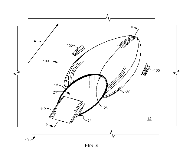
[0023] FIG. 4 is a forward perspective view of a duct outlet port fairing
assembly of the
present invention having a forward vane fairing, a Coanda fairing and a pair
of vortex
generator fairing which are arranged and mounted about an angled duct outlet
port of an
aircraft;
[0024] FIG. 5 is a cross-sectional view of the duct outlet port and the duct
outlet port fairing
assembly taken alone lines 5-5 of FIG. 4 and illustrating a reduction of
airflow turbulence
within and about the duct outlet port;
[0025] FIGS. 6A-61 depict various views of the forward vane fairing of the
duct outlet port
fairing assembly of FIG. 4;
[0026]FIGS. 7A-7F depict various views of the Coanda fairing of the duct
outlet port fairing
assembly of FIG. 4;
[0027] FIGS. 8A-8E depict various views of one of the vortex generator
fairings of the duct
outlet port fairing assembly of FIG. 4;
CA 03087380 2020-06-29
WO 2019/133276
PCT/US2018/065452
[0028]FIG. 9 is a forward perspective view of the outlet port fairing assembly
of FIG. 4
mounted about the angled duct and illustrating air flow over the surface of
the aircraft
proximate the duct outlet port;
[0029] FIG. 10 is a cross-sectional view of the aircraft having the outlet
port fairing assembly
of FIG. 4 mounted about the angled duct outlet port and displaying a computer
simulation of
non-turbulent air flow patterns being exhibited within and around the duct
outlet port; and
[0030] FIG. I IA (prior art) and FIG. 1113 are cross-sectional views of the
aircraft without and
with the outlet port fairing assembly mounted about the duct outlet fairing
assembly,
respectively, and comparatively displaying computer simulations of mixing of
high
temperature, low velocity duct flow with low temperature, high velocity
surface flow within
and around the duct outlet port with and without the duct outlet fairing
assembly.
(0031] To further facilitate an understanding of the invention, the same
reference numerals
have been used, when appropriate, to designate the same or similar elements
that are common
to the figures. Further, unless otherwise indicated, the features shown in the
figures are not
drawn to scale, but are shown for illustrative purposes only.
DETAILED DESCRIPTION OF THE EMBODIMENTS
(0032] The present invention is directed to a fairing assembly which is
positioned about an
angled duct outlet port of an aircraft or other vehicle in a manner that is
not parallel to an
exterior surface of the aircraft and in order to control the fluid flow
exiting the duct outlet
port. More specifically, the fairing assembly of the present invention turns
the fluid flow
exiting the duct outlet port in a direction of the surface flow over the
exterior surface of the
aircraft with minimized recirculation and drag. The fairing assembly includes
an upstream
vane to orient the surface flow with the duct flow, a downstream Coanda
fairing to aid in
turning the transverse duct flow in the direction of the surface flow, and a
pair of vortex
generators each of which is positioned at an opposing lateral side of the
Coanda fairing and
angled towards each other and angled towards each other to organize the
combined resultant
flow downstream of the duct outlet port with minimal recirculation, duct
restriction, and
overall vehicle drag. The fairing assembly of the present invention produces a
more
organized mixing of the duct and surface flows than any one of the fairing
components can
achieve individually.
6
CA 03087380 2020-06-29
WO 2019/133276
PCT/US2018/065452
(00331 Referring to FIGS. 4 and 5, the present invention relates to a duct
outlet port fairing
assembly 100 for positioning about a duct outlet port 22 of an aircraft 10 to
help minimize
turbulence and drag which is typically observed at prior art duct outlet
ports. The drawings
illustratively depict an embodiment of having a circular, nine inch diameter
exhaust duct
which is angled forty degrees to the exterior surface of the aircraft or
vehicle. The forward
vane fairing illustratively includes an optional structural feature to
smoothly fair out a design
flaw or structural impediment within the duct. Specifically, the vane fairing
has a member
that extends over a portion of the duct outlet, as well as inside the duct to
"fill in" the
downstream side of a structural relief protrusion. An illustrative forward
vane fairing that
specifically addresses this structural relief issue is shown and discussed
below with respect to
FIGS. 4, 5 and the other supporting images.
(0034] More specifically, the fairing assembly 100 includes a vane fairing 110
positioned at a
leading edge 24 of the duct outlet port 22, a Coanda fairing. 130 positioned
at a rear or trailing
duct edge of the duct outlet port 22, and at least one vortex generator vane
150 positioned
laterally to the Coanda fairing 130. The arrangement of the forward vane
fairing 110, the
Coanda effect fairing 130 and the vortex generator(s) 150 collectively alter
the direction of a
fluid flow exiting the duct outlet port 22 at an exterior surface 12 of an
aircraft 10 to better
coincide with the direction and angle of fluid flow over the exterior surface
12 of the aircraft
thereover.
[0035] Although the invention is described in terms of an aircraft duct 20
which serves as a
conduit to channel a flow of air or other fluids for release into the
atmosphere or external
environment via an outlet or port 22 thrmed on the exterior surface 12 of the
aircraft, such
type of transport vehicle is not considered limiting, as the fairing assembly
100 can be
implemented on other types of vehicles where altering the direction of fluid
flow exiting a
duct outlet is desirable. For example, the fairing assembly 100 can be
implemented on ships,
vessels, among other vehicles or duct outlet port and exterior surface
interfaces where it is
desirable to change the direction of flow of a fluid from the duct outlet with
respect to the
exterior surface.
(0036] Further, the fairing assembly 100 is shown and described with use with
a transverse
circular duct 22 having a nine inch diameter and orientated at a forty degree
angle to a surface
12. This duct 20 is typical to a large aircraft which is often used as the
heat exchanger outlet
for the passenger cabin pressurization system. A person of ordinary skill in
the art will
CA 03087380 2020-06-29
WO 2019/133276
PCT/US2018/065452
appreciate that the use, size and angle of the duct relative to the surface of
the vehicle is not
considered limiting, as the fairing assembly100 of the present invention can
be configured to
accommodate any size duct outlet on an exterior surface.
[0037] Referring now to FIGS. 4, 5 and 6A-61, the forward vane fairing 110 is
positioned
proximate the leading edge 24 of the duct outlet port 22. The forward vane 110
includes an
upper ramp portion 112 and an optional lower tongue portion 120, the latter of
which is
discussed below in further detail. The ramp portion 112 has a curved upper
surface 114 with
a leading edge 113 adjoined to the surface 12 of the aircraft fbrward of the
leading edge of the
duct outlet port 22, and a raised (upwardly sloped) trailing edge 115 to
direct the surface air
flow along the exterior surface of the aircraft at an upwardly sloped angle
away from the duct
outlet port 22. The ramp portion 112 also has a curved lower surface 116 to
direct or turn the
duct fluid flow in a direction towards the Coanda fairing 130 at the trailing
edge 26 of the
outlet port 22. The upper surface 114 is preferably convex in shape and the
lower surface 116
of the ramp portion 112 is preferably concave in shape to direct and turn the
surface air flow
and duct air flow, respectively.
[0038] The ramp portion 112 of the vane fairing 110 has a predetermined length
based on the
dimension of the duct outlet port. In particular, the length of the ramp
portion, as measured
linearly between the leading and trailing edges of the ramp portion, is in a
range between 0.5
and 0.9 duct outlet port diameters, and preferably 0.7 duct outlet port
diameters. Moreover,
the maximum height proximate or at the trailing edge 115 of the ramp portion
112, as
measured from the surface plane 12 of the aircraft is determined by the length
of the ramp
portion 110 and one-half of the duct angle. For example, a nine inch duct 20
having an angle
of forty degrees and a length of 0.7 diameters would have height of 2.1 inches
[(sine (0.5)(40
degrees)](9in.)(0.7diameters).
[0039] Referring to the cross-sectional view of FIG. 5, the upper surface 114
and lower
surface 116 extend partially over the outlet duct 22 such that the air surface
flowing at the
leading edge 24 of the outlet duct will follow along the curved upper surface
114 of the ramp
portion 112, as shown by arrow "B". Moreover, the duct flow (arrow "C") at the
leading
edge 24 of the duct outlet 22 is also turned towards the Coanda fairing 1.30
by the lower
surface 116 of the ramp 112. The surface flow and duct flow respectively
passing over the
upper surface 114 and lower surface 116 of the ramp 112 mixes and collectively
flows over
the Coanda fairing 130, which in turn redirects, i.e., turns the resultant
mixed fluid flow back
8
CA 03087380 2020-06-29
WO 2019/133276
PCT/US2018/065452
towards and along the exterior surface 12 of the aircraft 10, thereby reducing
turbulence and
drag proximate the duct outlet port 22.
[0040] The forward vane fairing 110 positioned at the leading edge 24 of the
duct 20
preferably bisects the angle of the duct 20 and the surface 12 within ten (10)
degrees of the
=de of bisection, and extends less than one-half (0.5) diameters of duct
outlet 22 length aft
from the leading edge 24 of the duct outlet port 22. For example, a nine inch
duct output port
of a forty degree angled duct 20 would be positioned at an angle between ten
and thirty
degrees (e.g., preferably approximately twenty degrees) with respect to the
surface 12, and
extend less than 4.5 inches over the duct outlet port 22. In one embodiment,
the ramp portion
112 of the forward vane fairing 110 covers between forty to ninety percent
(40% to 90%) of
the duct outlet's leading edge portion width, although such range is not
considered limiting.
For example, the coverage over the leading edge width can be plus or minus ten
percent
(10%).
[0041]The lower surface 116 of the ramp portion 112 is a smooth curve
extending parallel
from the duct surface upwardly towards the trailing edge 115. In one
embodiment, the lower
surface 116 is a spline, although such shape is not considered limiting. The
upper surface 114
has a curvature at its forward leading portion of 1/2 of the duct angle, and a
curvature at its rear
trailing portion of of the duct angle.
[0042]Referring to FIG. 2, the duct fluid flow shown by arrow "C" exiting out
of the outlet
port 22 collides or otherwise intermixes with the air flow over the surface 12
of the aircraft
10, as shown by arrow B. The flow from the duet C causes the surface air flow
to diverge
away from the exterior surface 12 of the aircraft 10 where the outlet port 22
is formed, and/or
recirculate (arrow "D"), thereby resulting in a combined or mixed airflow from
duct flow and
surface flow that is divergent, recirculating and decelerating, thereby
increasing drag aft of the
outlet duct 22. By comparison, referring to FIG. 5, the ramp portion 112 turns
the duct flow C
to reduce the angle that the flow exits the duct 22 and intermixes with the
surface flow B,
thereby reducing drag behind the outlet duct 22.
[0043] As discussed above with respect to FIG. 2, the duct conduit 20 which
terminates at the
outlet port 22 can often have protuberances, bends, obstructions, and other
structural
restrictions 30 therein, which can cause significant fluid flow disturbances
32 in the duct flow.
Some of these structural restrictions 30 can create fluid recirculation 32
within the duct 20,
which often leads to back pressure and restriction of the duct flow.
9
CA 03087380 2020-06-29
WO 2019/133276 PCT/US2018/065452
. [0044] in another embodiment, the forward vane fairing 110 includes a
tongue portion 120
extending from the lower surthce of the ramp portion 112, as illustratively
shown in FIGS.
6A-61. Referring to FIGS. 6A and 61, a top, rear right-side perspective view
and a bottom,
front right-side perspective view of the forward vane fairing 110 are
respectively shown. FIG,.
6E is a right side elevational view of the right side 118 of the forward vane
fairing 110. FIG.
6C is a top, front, right-side view thereof and FIG. 6G is a bottom, rear,
right-side view
thereof. FIGS. 6B and 6H are respectively a top plan view and a bottom view of
the forward
vane fairing 110. FIGS. 6D and 6F are left side and right side views of the
right side
elevational view of FIG. 6E, respectively.
[0045] Referring again to FIG. 2, an obstruction 30 is shown extending within
the duct 20,
which is causing recirculation and duct flow restrictions, i.e., drag within
the duct 20. To
address and solve for the recirculation/drag problem caused by the obstruction
30, the tongue
portion 120 of the forward vane fairing 110 is inserted into the duct 20 and
extends a distance
suitable to cover over the obstruction 30, thereby minimizing or negating the
undesired flow
recirculation effects caused by the obstruction 30.
[0046] Referring now to FIGS. 6A-6I, the tongue portion 120 includes a curved
lower surface
122 which illustratively conforms with the inner surface of the duct 20.
Although the duct 20
is discussed as having a predominately circular or curved interior surface,
such shape is not
considered limiting and the tongue portion 120 is preferably configured to
conform to the
interior surface of the duct 20. The curved lower surface 122 of the tongue
120 extends in a
direction towards and is integral with the lower surface 116 of the ramp
portion 112 to form
an underside surface 111 of the forward vane fairing 110. An upper surface 124
of the tongue
120 includes a notch or cutout 125 which conforms to fit around the
obstruction 30, as
illustratively shown in FIG.5.
[0047] The forward vane fairing 110 is positioned over the duct outlet port 22
such that the
leading edge 113 (FIG. 6A) is positioned forward of the duct outlet port 22
and the raised
trailing edge 115 extends over the duct outlet port 22. An underside 119 (Fla
6E) of the
ramp portion 112 is shaped to confbrm to the exterior surface 12 upon which it
is mounted.
Similarly, the upper surface 124 of the tongue 120 also conforms to the shape
of the interior
surface of the duct 20 and the obstruction 30.
[0048] The forward vane fairing 110 described and shown herein is suitable for
duct angles
greater than twenty degrees and less than 90 degrees to the surface 12 at
which the duct outlet
CA 03087380 2020-06-29
WO 2019/133276
PCT/US2018/065452
port is positioned. Preferably, the maximum duct relative velocity is between
two times the
surface flow at a twenty degree duct angle and one-half the surface flow at a
90 degree duct
angle during at least twenty percent of the operation of the vehicle, although
such duct
velocities and angle values are not considered lint iting.
[0049]Refening now to FIGS. 4, 5 and 7A-7F, the Coanda fairing 130 is
illustratively shown.
The Coanda fairing 130 is somewhat triangular or deltoid in shape and is
positioned and
extends rearward from the trailing edge 26 of the duct outlet port 22. More
specifically, the
Coanda fairing 130 is mounted on the surface 12 of the fuselage downstream of
the duct outlet
port 22 with its leading edge 132 located at the trailing edge 26 of the duct
outlet port 22. The
length of the Coanda fairing 130 is preferably less than three times the
diameter of the duct
outlet port 22, although such length is not considered limiting.
[0050] Referring now to FIGS. 7A-7F, the Coanda fairing 130 includes a leading
edge 132, a
trailing edge 134, a bottom 135, and a top surface 136. The bottom 135 can be
solid or
formed as a cavity when mounted over the exterior surface 12 of the aircraft
10. The leading
edge 132 of the Coanda fairing 130 conforms to the downstream half of the duct
outlet port
22, preferably with an initial transition surface angle of the duct exit angle
within +/- five (5)
degrees. The leading edge 132 is illustratively shown as circular in shape and
circumscribing
the shape of the trailing edge 26 of the duct outlet port 22. However, such
circular shape is
not considered limiting, as the leading edge 132 can be shaped to conform to
any other
configuration of the duct outlet port 22.
[0051] The length of the Coanda fairing 130, as measured longitudinally from
the foremost
leading edge 132 to the tip of the tailing edge 134, is based on the angle of
the duct 20 with
respect to the surface 12 of the aircraft 10. In particular, the Coanda
fairinv. 130 preferably has
a length of approximately three duct outlet port diameters per forty-five (45)
degrees of duct
angle. The length of the Coanda fairing "LC" can be expressed mathematically
as: LC
(DP*M) /45 degrees, where "DP" is the diameter of the duct outlet port (e.g.,
inches) and "M"
is a multiplier value of three (3), although such multiplier value is not
considered limiting.
For example, the multiplier M can be in a range of 1.5 to 3.0 duct outlet port
diameters and
still be operative to minimize recirculation of air flow. Accordingly, the
length of the Coanda
fairing 130 is longer for duct angles greater than forty-five degrees and
shorter for duct angles
less than forty-five degrees.
11
CA 03087380 2020-06-29
WO 2019/133276
PCT/US2018/065452
[0052] The length of the Coanda fairing 130 can be determined for a
differently angled duets
20 by the equation: LC = (DP*ML)/45 = X/DA, where "LC" is the length of the
Coanda
fairing along its longitudinal direction (e.g., inches), DP is the diameter of
the duct outlet port
(e.g., inches), ML is the length multiplier (e.g., 1.5-3.0), "IM" is the duct
angle, and "X" is
the length value being solved for by the equation. Accordingly, the length
value of "X" = LC
= (DP*ML*DA)/45.
[0053] For example, for a nine inch diameter duct and where a length
multiplier of three (3) is
selected, a duct 20 having a duct allele (DA) of thirty degrees would have a
Coanda fairing
length of approximately two duct outlet port diameters, i.e., eighteen inches.
Similarly,
applying the same set of criteria for a duct 20 having a steeper angle of
sixty-seven degree, the
Coanda fairing length would have a length of approximately 4.5 duct outlet
port diameters,
i.e., 40.5 inches. As noted above, although the Coanda fairing 130 preferably
has a length of
approximately three duct outlet port diameters per forty-five (45) degrees of
duct angle, such
length based on outlet port diameters per forty-five degree angle of the duct
20 is not
considered limiting, as the Coanda fairing is operable at a range of 1.5-3.0
duct outlet port
diameters per forty-five (45) degrees of duct angle.
[0054] The maximum height "HC" of the Coanda fairing 130 is approximately or
slightly
less than one-fifth (0.20) duct outlet port diameters of height per forty-five
degrees of duct
angle. Thus, the steeper the duct angle, the greater the height of the Coanda
fairing.
Conversely, for shallower duct angles, a lesser height is required per 45
degrees. The
maximum height of the Coanda fairing for any angled duct 20 can be found by
the equation:
MC (DP*M1-1)/45 = X/DA, where "MC" is the height of the Coanda fairing
(e.g., inches), DP
is the diameter of the duct outlet port (e.g., inches), Mil is the height
multiplier (ex., 0.15 to
0.25), "DA" is the duct angle, and "X" is the height value being solved for by
the equation.
Accordingly, the height value of "X" = MC = (DP*MH*DA)/45.
[0055) For example, selecting a height multiplier MM of 0.2 for a duct 20 that
is angled forty
degrees and having a nine inch diameter duct outlet port 22, the Coanda
fairing 130 will have
a height of approximately 1.6 inches. Using the same 0.2 height multiplier for
a duct 20
having a sixty-five degree duct angle (DA) with a nine inch diameter duct
outlet port 22, the
Coanda fairing will have a height MC of approximately 2.6 inches.
[0056] Referring to FIGS. 4 and 7A-7F, the width of the Coanda fairing 130 at
its widest
cross-section (normal to the longitudinal axis of the duct output port) can be
in a range of 1. 5
12
CA 03087380 2020-06-29
WO 2019/133276
PCT/US2018/065452
to a maximum of approximately 3.0 duct diameters in length. The Coanda fairing
130
circumscribes at least a portion (e.g., one-half) of the trailing edge 26 of
the duct outlet port
22 and increases in width in a direction towards the trailing edge 134 of the
Coanda fairing,
with a maximum width located approximately normal to the rearmost portion of
the trailing
edge with respect to the longitudinal axis of the duct outlet port. 22. The
width gradually
decreases in the direction of the Coanda trailing edge 134 which form an apex
of the
triangularly shaped Coanda fairing 130. The upper surfrtce 136 of the Coanda
fairing 130
preferably terminates at less than 33% of the duct angle at the fairing aft
point 133. For
example, if the angle of the duct 20 is forty-five .degrees, then the trailing
edge 134 of the
Coanda fairing terminates at 15 degrees.
[0057] The height along the upper surface 136 is fairly constant transverse to
the longitudinal
centerline of the Coanda fairing, as illustratively shown in FIGS. 7E and 7F.
The upper
surface 136 proximate the periphery or lateral edges of the Coanda fairing
increase in
tapering 137 to extend downwardly in the direction towards the aircraft
surface 12 upon
which the Coanda fairing is mounted. The height of the upper surface 136 is
fairly constant in
the longitudinal direction of the Coanda fairing 130 as shown in FIG. 7C, and
gradually
curves downwardly in the aft direction to the trailing edge aft point 133,
where the tapering
increases to the surface 12 of the aircraft 10 in a same manner as along the
lateral edges of the
Coanda fairing 130.
(0058] Referring to FIG. 4, the fairing assembly 100 flintier includes a pair
of vortex
generators 150 located on the aircraft surface 12, aft of the duct outlet port
22 and located
within twenty (20) degrees of parallel to the sides of the Coanda fairing,
Each vortex
generator 150 is laterally spaced preferably less than one duct diameter from
the centerline of
the duct outlet port 22. Referring to FIGS. 8A-8E, various views of one of the
vortex
generator fairings 150 is illustratively shown. FIG. 8A depicts a top, forward
perspective
view. FIG. 8B depicts a side elevational view, FIG. 8C depicts a top plan
view, FIG. 81)
depicts a rear elevated view, and FIG, 8E depicts a bottom view of a vortex
generator fairing
150. The fairing 150 includes a substantially elongated, planar base 152
having a bottom
surface 153 which conforms to the aircraft surface 12 upon which it is
mounted, and an upper
surface 154 upon which an elongated upright or dorsal member 156 extends
perpendicularly
upward therefrom, as illustratively shown in FIG. 81). However, a person of
ordinary skill in
the art will appreciate that the upright member 156 can be angled, e.g.,
inwardly in a direction
13
CA 03087380 2020-06-29
WO 2019/133276 PCT/US2018/065452
towards the lateral portions of the Coanda fairing 130. The elongated dorsal
member 156 is
shown having a same longitudinal length as the base 152, although such base
length is not
considered limiting. The length of each dorsal member 156 of the vortex
generators is
determined by the optimum aspect ratio of conventional vortex venerators at
three times the
height. For example, a nine inch duct diameter will have a height in a range
of 0.90 to 2.7
inches and a respective length in the range of 2.7 to 8.1 inches. The height
of the dorsal
member 156 of the vortex generators 150 is ten to thirty percent of the duct
diameter.
Additionally, a leading edge 158 of the dorsal member 156 preferably has a
convex shape and
curves downwardly from a top edge 159 of the dorsal member 156 to the upper
surface 153 of
the base 152, although such convex shape is not considered limiting.
Preferably, the vortex
generators are equipped with a full height radius on the leading edge.
[0059] The vortex generators 150 are positioned aft of the duct within two
duct diameters.
The generators are angled between fifteen (15) and thirty (30) degrees to the
duct's
longitudinal axis and generate a pair of convergent, counter-rotating vortices
which converge
behind the Coanda fairing. The purpose of the vortex generators is to create
organized vortex
flow on each side of the duct outlet port flow to help prevent disorganized
recirculation of the
freestream and duct flows.
[0060] The configurations of the forward vane fairing 110, the Coanda fairing
130, and the
vortex generators can be generated by 3D CAD software program (e.g., Solid
Works program
by Dassault Systemes Solid Works Corp. of Waltham, MA, USA). A person of
ordinary skill
in the art will appreciate that any commercially available computer aided
design software can
generate the fairing profiles from the predetermined dimensions and level of
definition. For
purposes of better understanding the invention, a computer model of a BOEING
737 aircraft
is illustratively used, but such model aircraft is not considered limiting.
[0061] Referring again to FIG. 5, the aircraft 10 is shown flying through the
air with its duct
flow exiting from the duct outlet 'port 22. The surface air B flows over the
ramp portion 112 of
the forward vane failing 110 and is turned slightly upward over the open area
of the duct
outlet port 22. At the same time, the duct flow C exiting the duct 20 is
deflected by the
tongue 120 which covers the obstruction 30 in the duct 20 and follows the
contour of the
underside 116 of the ramp portion 110. The duct flow turns in a rearward
direction within the
duct with minimal recirculation and restriction caused by the duct obstruction
30. The duct
flow C exiting the outlet port 22 intermixes with the surface flow B passing
over the ramp 112
14
CA 03087380 2020-06-29
WO 2019/133276
PCT/US2018/065452
with minimal recirculation and the intermixed stream flows over the Coanda
fairing 130 such
that the resultant fluid stream flow follows the contour of the Coanda fairing
130 and is turned
in a direction towards the aircraft surface 12. The resultant stream flow that
is lateral to the
Coanda fairing 130 is further streamlined rears,vardly in a direction of the
longitudinal axis of
the duct outlet port 22 by the inwardly angled opposing vortex generators 150.
Accordingly,
turbulence aft, over and rearward of the duct outlet port 22 is minimized, as
illustratively
shown in FIG. 9. In particular, referring to FIGS. 1 and 9, the broken or
dashed lines in FIG.
1 represent "slices" of transverse velocities illustrating highly disorganized
flow for the
unmodified duct outlet port 22, while FIG. 9 illustrates how the fairing
assembly 100 of the
present invention provides highly organized flow for the modified duct outlet
port 22.
[0062]FIGS. 3, 10, 11A-1113 are representations of various views of screen
shots of
computer-simulated aircraft to illustrate comparative effects on airflow with
and without the
duct outlet fairing assembly 100 of the present invention mounted on the
aircraft. FIGS. 3A
and 11A are cross-sectional views of a prior art aircraft without the duct
outlet fairing
assembly 100 of the present invention. FIGS. 10 and 1113 are cross-sectional
views of the
aircraft with the duct outlet fairing assembly 100 of the present invention
mounted on a
portion of the fuselage. The drawings were taken from color-coded computer
simulations
which were configured and performed by the inventors using the well-known NASA
"Common Resource Model" (CRM) from the 5th A IAA Drag Prediction Workshop,
although
such simulation program is not considered limiting. The simulations conducted
were from an
industry standard model of a 767/777/A330/A350 class aircraft. The CRM is used
throughout
the industry in wind tunnel and computational fluid dynamics (CFD) work to
develop an
understanding of drag and how to predict it. The figures illustrate air flow
over unmodified
model aircraft without the duct output port fairing assembly and modified
models with the
angled duct output port fairing assembly mounted about an angled duct output
port located on
the fuselage of the aircraft. In interpreting these images, undesirable flow
from the angled
duct 20 causing drag is bent or recirculated (e.g., reversed), while lower
drag flow bends and
recirculates less. High surface pressure areas (HP) are illustrated by darker
shading, as
compared to low surface pressure (LP) areas which are illustrated by lighter
shading at
specific areas of the aircraft.
[0063]Referring to FIG. 3, a significant amount of turbulence is caused by the
obstruction 30
in the angled duct 20, as well as the duct flow exiting the duct outlet port
22 and colliding
CA 03087380 2020-06-29
WO 2019/133276 PCT/US2018/065452
with the surface flow stream. By comparison, FIG. 10 illustrates that the
recirculation and
restriction within the duct is predominately eliminated by the forward vane
110, and the
mixing of the duct flow and surface flow over the Coanda fairing 130, which is
further guided
and streamlined between the pair of vortex generators 150 results in a
smoothed, less turbulent
surface flow rearward of the Coanda fairing 130.
[0064] Referring to FIG. 11A, a temperature plot shows disorganized mixing of
high
temperature, low velocity duct flow with low temperature, high velocity
surface flow for the
unmodified duct outlet port 22. By contrast, FIG. 11B illustrates organized
temperature flow
mixing for the modified duct outlet port 22 with the fairing assembly 100 of
the present
invention. Accordingly, FIGS. 3 and I IA illustrate undesirable large angles
of recirculating
air flow exits the angled duct outlet port 22. By contrast, the duct outlet
fairing assembly 100
of the present invention causes the air flow to dampen or flatten around the
Coanda fairing
130 and streamline between the pair of vortex generators 150 so that the
combined or resultant
surface and duet flows with minimal turbulence closer to the surface 12 of the
aircraft 10.
[0065]The fairing assembly 100 can be constructed of molded fiberglass and
epoxy thr
electromagnetic transparency in multiple steps. Alternatively, the fairing can
be fabricated
from composite materials such as quartz, fiberglass, carbon fiber, Kevlar,
Vectran or other
aerospace grade reinforcing fibers and plastics. The fairing assembly 100 can
also be
fabricated from metals such as aluminum, steel, stainless steel, titanium, or
other aerospace
grade metals, or a combination of composite and metal materials. Processes for
fabricating
the fairing assembly 100 can include molding, machining, additive
manufacturing, or
combination of these practices. Once the fabrication process of the fairing
assembly 100 is
completed, the fairing assembly can be attached as a kit to older aircraft, or
incorporated in to
the fuselage a part of a new aircraft design.
[0066] Advantageously, the present duct outlet fairing assembly 100 can be
implemented
after the fuselage designs have been frozen or are already in production. For
a newly
designed aircraft, the fairing assembly can be iterative and be optimized with
regard to the
other components. A person of ordinary skill in the art will appreciate that
other embodiments
of the duct outlet fairing assembly 100 can be formed and positioned in a
similar manner
described above fur various aircraft models and at different locations on the
fuselage.
[0067] While the foregoing is directed to embodiments of the present
invention, other and
further embodiments and advantages of the invention can be envisioned by those
of ordinary
16
CA 03087380 2020-06-29
WO 2019/133276
PCT/US2018/065452
skill in the art based on this description without departing from the basic
scope of the
invention, which is to be determined by the claims that follow.
17