Note: Descriptions are shown in the official language in which they were submitted.
CA 03087470 2020-06-30
WO 2019/139938
PCT/US2019/012828
Micro Bi-Directional Valves and Systems
Priority Claim Under 35 U.S.C. 119
This application claims priority under 35 U.S.C. 119 to U.S. Provisional
Patent Application Serial No. 62/615,064, filed January 9, 2018, and entitled
"Micro
bi-Directional Valves and Systems," the entire contents of which are hereby
incorporated by reference.
BACKGROUND
This specification relates to fluid flow systems and in particular CPAP
devices.
A somewhat common medical disorder, sleep apnea, involves a reduction or
pause in breathing (airflow) during sleep. Sleep apnea is common among adults
but
rare among children. Treatments for sleep apnea can include surgical
procedures or
nonsurgical treatments that can involve behavioral changes dental appliances
and
mouthpieces. One nonsurgical treatment involves CPAP (continuous positive
airway
pressure) devices.
Continuous positive airway pressure (CPAP) is a non-surgical treatment that
uses a machine to supply air pressure to hold a user's airway open so that it
does not
collapse during sleep. A machine delivers air through a nasal or face-mask
under
pressure. The machine blows heated, humidified air through a tube to a mask
that is
worn snugly to prevent the leakage of air. Masks come in several forms
including
nasal pillows, nasal masks, and full-face masks. Various CPAP machines are in
use.
Typically, the CPAP machine is a little larger than a toaster, it is generally
portable so
that it can be taken on trips. However, existing CPAP treatments are not easy
to use,
as it is not easy to sleep with a mask that blows air into the nose also such
CPAP
machines/masks are generally required to be cleaned periodically so as to
avoid build-
up of bacterial, viruses, etc.
One example of a miniature CPAP device that is based on a micro pump (or
micro blower) is disclosed in US-2015-0267695-Al and another is disclosed in
US-
2016-0131126-Al, the entire contents of which are incorporated herein by
reference.
1
CA 03087470 2020-06-30
WO 2019/139938
PCT/US2019/012828
SUMMARY
Disclosed here in a bi-directional valve. By bi-directional is meant that
airflow into and out of the valve occurs on a bidirectional port side with
relative ease
such that outflow of air does not encounter significant resistance from a
continuous
inflow of air in the bi-directional valve.
While such a valve would be useful in many applications, it is especially
useful in a miniature CPAP device as disclosed in US-2015-0267695-Al and US-
2016-0131126-A1. Such CPAP devices are configured to be very small, in
comparison to the more conventional CPAP devices. Such a valve could also be
useful with the more conventional CPAP devices and especially in masks used
with
these more conventional CPAP devices.
According to an aspect, a valve includes a valve body having a center
chamber, a plurality of side chambers, and an elongated compartment and a
plurality
of bidirectional ports coupled to the center chamber via a set of passages to
provide
fluid ingress into the bi-directional valve in a first mode of operation or
fluid egress
from the bi-directional valve in a second mode of operation, and a plurality
of
unidirectional ports coupled to the plurality of bidirectional ports to
provide providing
fluid egress from the valve in the second mode of operation, and a single
unidirectional port to provide fluid ingress into the bi-directional valve in
the first
mode of operation, a mechanism including a center paddle and a plurality of
side
paddles, and a shaft supporting the center paddle and the plurality of side
paddles
along the length of the shaft, the shaft disposed in the elongated compartment
of the
valve body and allowed to pivot to cause the center paddle and the plurality
of side
paddles to open and close the input and output ports according the first and
second
modes.
According to an additional aspect, an airway pressure breathing device
includes an airway pressure breathing device body having at least one air
passage to
receive air and at least one passage to expel air, and a bi-directional
exhalation valve.
The bi-directional valve is coupled to the at least one air passage to receive
air and the
at least one air passage to expel air, and includes a valve body having a
center
chamber, a plurality of side chambers, and an elongated compartment and a
plurality
of bidirectional ports coupled to the center chamber via a set of passages to
provide
2
CA 03087470 2020-06-30
WO 2019/139938
PCT/US2019/012828
fluid ingress into the bi-directional valve in a first mode of operation or
fluid egress
from the bi-directional valve in a second mode of operation, and a plurality
of
unidirectional ports coupled to the plurality of bidirectional ports to
provide providing
fluid egress from the valve in the second mode of operation, and a single
unidirectional port to provide fluid ingress into the bi-directional valve in
the first
mode of operation, and a mechanism including a center paddle and a plurality
of side
paddles, and a shaft supporting the center paddle and the plurality of side
paddles
along the length of the shaft, the shaft disposed in the elongated compartment
of the
valve body and allowed to pivot to cause the center paddle and the plurality
of side
paddles to open and close the input and output ports according the first and
second
modes.
The details of one or more embodiments of the invention are set forth in the
accompanying drawings and the description below. Other features, objects, and
advantages of the invention are apparent from the description and drawings,
and from
the claims.
DESCRIPTION OF DRAWINGS
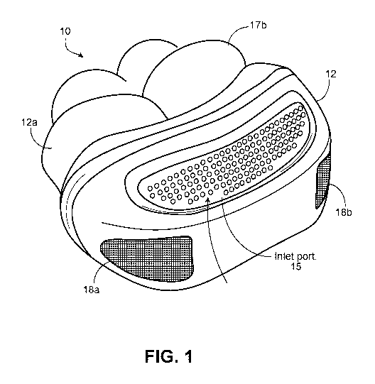
FIG. 1 is a diagram of a miniature CPAP device.
FIG. 2 is a functional block diagram of a miniature CPAP device employing
micro pumps that operating in two opposite phases of a pumping cycle, as
disclosed
in the above published applications.
FIGS. 3A-3I are somewhat isometric views of a bidirectional valve for the
miniature CPAP device of FIGS. 1 and 2.
FIG. 4 is a diagram depicting the bidirectional valve in a mask of a more
conventional CPAP.
DETAILED DESCRIPTION
Overview
As disclosed in the above co-pending incorporated by reference patent
applications micro pumps can be made using micro fabrication methods and can
be
used for performing micro pumping processes that are widely implemented in
industrial, medical, and biological applications. For example, micro pumps can
be
3
CA 03087470 2020-06-30
WO 2019/139938
PCT/US2019/012828
incorporated into CPAP devices. The micro pumps can transport fluids, e.g.,
gas or
liquids, in small, accurately measured quantities. In some implementations,
the micro
pumps can transport the fluids at high flow rates, e.g., about microliters per
second to
about a few milliliters per second, and/or high pressure, e.g., about
thousandths of one
psi to about tenths of one psi. The micro pumps can be designed such that the
fluid
transport, the flow rates, and/or the pressure are scalable.
Referring now to FIG. 1, an autonomous device for treating breathing
disorders 10 (device) is shown. The device 10 is a CPAP type (continuous
positive
airway pressure) breathing device. However, the CPAP device 10, unlike CPAP
machines, is an autonomous device that is local to the nose and which provides
a
required amount of air flow at a required pressure to treat various breathing
disorders
such as obstructive sleep apnea ("OSA").
The CPAP device 10 can take a conceptual form as disclosed in the above
applications. In this configuration, the CPAP device 10 includes a body 12
that
houses micro pumps 16 here plural component-pump stacked elements generally
denoted by a curved line, indicating that the micro pumps are disposed behind
an inlet
port 15. (See FIG. 2 for a functional location and the incorporated by
reference
applications for details.) The CPAP breathing device 10 includes a bi-
directional
valve that is used as an exhalation valve (not shown, but see FIGS. 2 and 3A-
3H and
4). The CPAP device 10 has cushioned plugs 17a, 17b with air passages through
the
cushioned plugs 17a, 17b that provide a nasal interface. The cushioned plugs
17a,
17b are made of a generally rubbery material that makes a tight fit when
inserted into
a user's nostrils. The CPAP device 10 has one or as shown two outlets 18a, 18b
for
exhalation of air.
Referring now to FIG. 2, a schematic, e.g., of the configurations shown in
FIG. 1, includes a bidirectional valve 20 coupled to the micro pump 16 within
the
CPAP device 10. As fluid, e.g., air is pushed into one or more inlet ports of
the valve
20, the one or more inlets open and the valve 20 opens a passage from the one
or
more inlets to one or more bidirectional ports to expel the fluid, e.g., air
from the
bidirectional ports of the valve 20. When a fluid, e.g., air flow external to
the valve is
forced into the one or more bidirectional ports, the air flow pushes the inlet
of the
valve 20 shut while opening one or more outlet ports of the valve 20 at the
end of the
4
CA 03087470 2020-06-30
WO 2019/139938
PCT/US2019/012828
bidirectional ports. This action of the valve will occur even while air is
blowing
against the inlet ports provided the pressure exerted into the bidirectional
ports is
sufficient to overcome the pressure of air blowing against the inlet ports. In
the
context of a CPAP device the valve 20 is referred to herein as an exhalation
valve 20.
The exhalation valve 20 has inlets 20a, 20b and outlets 21a, 21b. The
exhalation valve 20 is coupled between the micro pumps 16 (via the exhalation
valve
inlets 20a, 20b and inlets 16a, 16b of the micro pump 16) and outlets 18a, 18b
of the
device 10, (via the exhalation valve ports 21a, 21b), as shown. The inlets
16a, 16b of
the micro pump 16 are coupled to inlet port 15 of the CPAP device 10.
The above mentioned patent applications disclose an exhalation valve of a
butterfly configuration having a flap that is disposed inside a passageway of
the valve.
The flap is rotatable about an axial member to open and close the passageway
that is
between a pair of ports and an outlet port. The exhalation valve 20 discussed
below is
an alternative to the exhalation valve in the above applications and will now
be
described.
Referring now to FIGS. 3A-3H, various views of the exhalation valve 20
having a bi-directional valve configuration is shown. The exhalation valve 20
has a
paddle mechanism that uses air flow from the micro pumps 16 to close passages
in the
exhalation valve 20 at the end of an exhalation/beginning of pause in
breathing and at
.. the beginning of exhalation. The exhalation valve 20 opens even as the
micro pumps
blow air on the exhalation valve 20. The CPAP device 10 is configured to
select how
much of the micro pumps' 16 air flow is needed to push the valve 20 shut.
Pressure
from the micro pumps 16 will hold the exhalation valve 20 shut prior to
exhalation.
All of the exhalation air flow from a user is applied to the exhalation valve
20 to open
.. the exhalation valve 20. The shape of the valves' flaps on the paddle may
be
optimized to assist the exhalation valve 20 to remain open during exhalation.
In
addition, weak magnetics may also be used to keep exhalation valve 20 open or
closed depending on details of a design. The exhalation air from a user would
generally be sufficient to overcome a minimum amount of air flow from the
micro
pump to keep the exhalation valves 20 closed.
Referring now to FIG. 3A, show is the valve 20 including a body 41, a single
unidirectional port 43 that is in this implementation used as an inlet, bi-
directional
5
CA 03087470 2020-06-30
WO 2019/139938
PCT/US2019/012828
ports 45a and 45b, a plurality of unidirectional ports that are in this
implementation
used as outlet ports 47a, 47b. Each of the outlet ports has a paddle (or flap)
49a, 49b,
respectively that selectively closes and opens the respect port 49a, 49b. The
inlet port
43 also has a paddle (or flap) 51. The paddles 49a, 49b and 51 are flat
members and
are part of paddle valve mechanism 55. The paddle valve mechanism 55 is
rotatable
with an axial compartment 57 (FIG. 3B) provided in the body 41 at body portion
41a
to open and close passageways among ports 45a, 45b, 49a, 49b and 51, as will
be
described.
FIG. 3B shows the arrangement of FIG. 3A in an exploded view. This view
shows passages 46a, 46b and 50 through the body 41. As shown in FIG. 3B the
body
41 has the bi-directional ports 45a and 45b and outlet ports 47a, 47b coupled
by
cylindrical members or portions 41a, 41b of the body 41, the single
unidirectional port
43 provided by a rectangular member or portion 41c of the body 41, and the
axial
compartment 57 that receives the paddle valve mechanism 55.
FIG. 3C shows the paddle valve mechanism 55 with the paddles 49a, 49b, at
the ends of the shaft 53 and the paddle 51 disposed (centrally) between the
side
paddles 49a, 49b, i.e., central paddle 51. The side paddles 49a, 49b are
orthogonal to
the central paddle 51 and are supported on the shaft 53 that rotationally
pivots about
its axis when disposed in the axial compartment 57 (FIG. 3B). The mechanism 55
also
includes an compartment seal 65.
While, the central paddle 51 in this embodiment is generally orthogonal to the
side paddles 49a, 49b other configurations of the body 41 could provide other
positioning configurations of the paddles on the shaft. Also while two side
paddles
(and hence two bidirectional ports 45a, 45b and two outlet ports 47a, 47b are
shown)
more or fewer side paddles may be used. Also while a single inlet port 43 is
shown in
some configurations plural inlet ports could be used. Configurations with more
than
two outlet ports and two bi-directional ports and more than one inlet port
would
necessitate adjustments to the mechanism 55.
Referring now to FIGS. 3D-3E, these views show the valve 20 from a front
elevation view (FIG. 3D) and frontal view broken away (FIG. 3E) exposing
internal
passages 63a, 63b and chambers 60a, 60b and 61. The chambers 60a, 60b are side
chambers and are shown disposed between outlet ports 47a, 47b and
bidirectional
6
CA 03087470 2020-06-30
WO 2019/139938
PCT/US2019/012828
ports 45a, 45b. The chamber 61 is a central chamber. The passages 63a, 63b are
provided from central chamber 61 to the side chambers 63a, 63b, as also shown.
Also
shown in FIGS 3D-3E is a axial compartment seal 65 that seals the axial
compartment
57 of FIG. 3A. In FIG. 3D the cross sections "FIG. 3G" and "FIG. 31" reference
FIGS. 3G and 31, respectively.
Referring now to FIGS. 3F-3G, these views (somewhat simplified in cutaway
view) show the valve 20 in a first mode of operation. FIGS. 3F-3G show
internal
details of the central chamber 61 and the passageways 63a, 63b (63b being
shown in
FIGS. 3F-3G) in which the paddle valve mechanism 55 rotates within the axial
to compartment 57 provided by the body 41 to force the central paddle 51
into the open
position. When central paddle 51 is in the open position (upright as shown in
FIG.
3G) that opens the one way inlet port 43 and allows air to flow through
orifice or
passage (only 63b is labeled) between center chamber 61 and side chambers 60a,
60b
(only 60b is labeled), while forcing the side paddles 49a, 49b to close the
air outlet
ports 47a, 47b. This mode allows air to flow from the inlet port 46 to the
bidirectional
ports 45a, 45b, but not out the air outlet ports 47a, 47b, as denoted by the
arrows
labeled 70 (shown for one side of the valve 20). This would correspond to the
user
inhaling air from the micro pumps 16.
FIGS. 3H-3I show internal details of the central chamber 61 and the
passageways 63 in which the paddle valve mechanism 55 rotates within the axial
compartment 57 provided by the body 41 to force the central paddle 51 into the
closed
position that closes the one way inlet port 43 and inhibits air to flow
through orifice or
passage (only 63b is labeled) between center chamber 61 and side chambers 60a,
60b,
while forcing the side paddles 49a, 49b to open the air outlet ports 47a, 47b.
This
mode allows air to flow from the bidirectional ports 45a, 45b out the air
outlet ports
47a, 47b, as denoted by the arrows labeled 72 (shown for one side of the valve
20).
This would correspond to the user exhaling air from the user's nostrils.
Passages between the air outlet ports 47a, 47b and the bidirectional ports
45a,
45b are, in general rounded, but other shapes could be used. Passages 63a, 63b
can be
rounded, oblong, etc. The central passage 61 is somewhat rectangular. However,
any
shapes could be used for the passages, ports, chambers, etc. and in general
all surfaces
and interior passages, ports, chambers, etc. are smooth. Dimensions of the
various
7
CA 03087470 2020-06-30
WO 2019/139938
PCT/US2019/012828
components of the exhalation valve 20 would be selected according to various
design
considerations, such as the volume of air that will be convected during modes
of
operation, the size of the CPAP device 10, and available space within the CPAP
device 10.
Thus the bi-directional exhalation valve 20 includes the valve body 41 having
the center chamber 61 and a plurality of side chambers (here two) 60a, 60b,
and the
elongated compartment 57. The plurality of bidirectional ports 45a, 45b (here
two)
are coupled to the center chamber 61 via the set of passages 63a, 63b to
provide fluid
ingress into the bi-directional valve 20 in a first mode of operation
(inhalation) or
fluid egress from the bi-directional valve 20 in a second mode of operation
(exhalation). The plurality of unidirectional ports 47a, 47b act as output
ports and are
coupled to the plurality of bidirectional ports to provide fluid egress from
the valve in
the exhalation mode of operation, and a single unidirectional port 51 to
provide fluid
ingress into the bi-directional valve 22 inhalation. The paddle mechanism
including
the center paddle and the plurality of side paddles, and a shaft supporting
the center
paddle 51 and the plurality of side paddles 49a, 49b along the length of the
shaft 53,
the shaft 53 is arranged in the elongated compartment of the valve body, such
that the
shaft 53 is rotatable within the elongated compartment in the body.
The bi-directional valve 20 when used as the exhalation valve 20 in the CPAP
device may allow a user to more easily overcome pressure caused by incoming
air
from the micro pump (micro blowers) during exhalation of air from the nose
passages.
This provides a more comfortable and improved breathing experience with CPAP
device 10. When used in an airway pressure breathing device, e.g., the CPAP
device
10, the bi-directional exhalation valve 20 is coupled to the at least one air
passage to
receive air from the CPAP device (e.g., the micro pump in a micro CPAP device
or
from a conventional CPAP) and the at least one air passage to expel air. The
CPAP
airway pressure breathing device 10 body has at least one air passage to
receive air
from a source of air, and which is coupled to the plurality of bidirectional
ports of the
bi-directional exhalation valve 20. The CPAP device 10 also has at least one
passage
to expel air that is coupled to the plurality of unidirectional ports of the
bi-directional
exhalation valve 20. The airway pressure breathing device can have the source
of air
being a micro pump supported by the airway pressure breathing device body
where
8
CA 03087470 2020-06-30
WO 2019/139938
PCT/US2019/012828
the micro pump is configured to pump ambient air through the air passages and
the bi-
directional exhalation valve.
Not being bound by the foregoing, but in the context of a CPAP device,
operation can be approximated as follows: during inhalation, pressure Pb at
the
bidirectional ports is approximately related to Pb = P + Ph (the sum of
pressure
from the micro pump Pi plus the pressure of inhalation Ph ), whereas during
exhalation pressure Pb at the bidirectional ports is approximately related to
Pb = Pe
Pi (the sum of pressure from exhalation Pe (a negative pressure or vacuum)
plus the
pressure Pi from the micro pump, a positive pressure). Provided that Pb is
positive
to during inhalation and Pb is negative during exhalation, the valve 20
will operate in a
bidirectional manner.
In other embodiments, the airway pressure breathing device body is a mask
that is configured to be secured over a user's head and/or against a user's
nostrils,
with the mask configured to receive a hose as discussed below in FIG. 4.
Referring now to FIG. 4, a mask 80 is shown, which mask 80 is typical of a
conventional nasal mask used with conventional CPAP machines (not shown). The
mask 80 includes a hose attachment 82 (for a hose 84 that couples to the CPAP
machine) and has a harness 86 that secures the mask 80 to the user positioning
air
outlets under the nose of a user. Unlike a conventional mask, the mask 80 also
includes the exhalation valve 20 that is fitted to and positioned within the
mask 80
such that the exhalation valve 20 allows a user to more easily overcome
pressure
caused by incoming air from the CPAP machine during exhalation of air from the
nose passages, by use of the operations depicted in FIGS. 3E-3H. Thus, the
exhalation
valve 20 would be connected in the mask 80 in such a manner that an outlet
(not
referenced) from the hose 84 is coupled to the inlet port 51 of the exhalation
valve 20.
The outlet ports 47a, 47b of the exhalation valve 20 would be coupled to
corresponding ports on the mask 80, which are used to expel air during
exhalation.
The bidirectional ports 45a, 45b are coupled to plugs (not shown) having
openings to
allow the user to breath air in (via the inlet port 51) and expel air out (via
the outlet
ports 47a, 47b).
9
CA 03087470 2020-06-30
WO 2019/139938
PCT/US2019/012828
In order to satisfy various design considerations for different types of masks
as
well as different configurations of CPAP devices 10 the physical form of the
exhalation valve may be altered from that shown in the figures.
Various techniques can be used to produce the exhalation valve 20, including
molding the device from suitable (medical grade) plastic materials, 3D
printing
techniques, and so forth.
The exhalation valve 20 would generally have dimensions suitable for the
application. Thus for example in the CPAP device 10 as envisioned in the
incorporated by reference applications the dimensions are on the order of 10's
or
1() 100's of millimeters. In some applications of the exhalation valve 20
the valve can be
smaller or larger.
Elements of different implementations described herein may be combined to
form other embodiments not specifically set forth above. Elements may be left
out of
the structures described herein without adversely affecting their operation.
Furthermore, various separate elements may be combined into one or more
individual
elements to perform the functions described herein. Other embodiments are
within
the scope of the following claims.