Note: Descriptions are shown in the official language in which they were submitted.
1
STRADDLED VEHICLE
The present invention relates to a saddled vehicle including an inertial
measurement unit.
An ABS (Antilock Brake System) may be provided in a motorcycle. An IMU
(Inertial
Measurement Unit) is used to control the ABS, for example. In the following
description,
the IMU is suitably referred to as an inertial sensor.
The inertial sensor includes an acceleration sensor, and detects acceleration
exerted on the vehicle provided with the inertial sensor in the directions of
three axes
orthogonal to one another. Further, the inertial sensor includes a gyro
sensor, and detects
an angular velocity generated around each of the above-mentioned three axes in
regard to
the vehicle provided with the inertial sensor. The ABS is controlled based on
at least part
of a plurality of accelerations and a plurality of angular velocities detected
by the inertial
sensor. Thus, the braking force exerted on a front wheel or a rear wheel is
adjusted
according to a traveling state of the vehicle.
In a case where the inertial sensor is provided in the motorcycle, vibration
generated from an engine may be transmitted to the inertial sensor depending
on the
attachment state of the inertial sensor. Further, vibration caused by the
vertical movement
of the front wheel or the rear wheel may be transmitted to the inertial sensor
depending on
the state of the road surface on which the motorcycle travels. The vibration
reduces the
detection accuracy of acceleration and an angular velocity by the inertial
sensor.
As such, the configuration for reducing various types of vibration transmitted
to the
inertial sensor in the motorcycle has been proposed. For example, in the
attachment
structure of an inertial sensor described in JP 2017-13731 A, a floating
bracket is fixed to a
body frame via a vibration absorbing member. In this state, the inertial
sensor is attached
to a first attachment surface of the floating bracket, and an ABS unit is
attached to a
second attachment surface of the floating bracket.
However, even in a case where the structure described in JP 2017-13731 A is
applied, the detection accuracy of acceleration and an angular velocity by the
inertial
sensor may be reduced. Specifically, in the motorcycle described in JP 2017-
13731 A, the
inertial sensor is provided while being exposed to the outside of the
motorcycle. Therefore,
rainwater and dust are likely to adhere to the inertial sensor during
traveling of the vehicle.
The adherence of rainwater and dust to the inertial sensor may reduce the
detection
accuracy of inertia by the inertial sensor.
Further, in a case where the inertial sensor is located at a position where
the inertial
sensor is easily accessed from outside of the motorcycle, the position or
orientation of the
inertial sensor may be erroneously changed by a user of the motorcycle. With
the structure
described in JP 2017-13731 A, the inertial sensor is attached to a plate-
shaped floating
bracket and fixed to the body frame while being exposed. Therefore, in the
motorcycle
CA 3087548 2020-07-16
2
described in JP 2017-13731 A, it can be said that the inertial sensor is
relatively easily
accessible from outside of the motorcycle. The position and orientation of the
inertial
sensor in the motorcycle are defined so as to comply with the conditions
designed in
advance. Therefore, in a case where the position and orientation of the
inertial sensor
provided in the motorcycle are changed after the motorcycle is shipped from
the factory,
the acceleration and angular velocity to be detected are not detected.
Further, It is generally desirable to miniaturize a motorcycle. Therefore, no
wasteful space is essentially provided in the motorcycle. Therefore, in a case
where an
electric appliance such as an inertial sensor is added to the motorcycle, it
is necessary to
secure a new installation space for installing the additional electric
appliance. In this
case, the size of the motorcycle is increased.
An object of the present invention is to provide a straddled vehicle
enlargement of
which to be caused by provision of an inertial measurement unit can be
suppressed while
high detection accuracy of inertia by the inertial measurement unit can be
maintained.
According to the present invention said object is solved by a straddled
vehicle having
various features described herein.
Generally, a motorcycle is provided with a battery case that stores a battery.
As
such, in regard to the above-mentioned problem, it can be considered that it
was possible
to prevent the inertial measurement unit from being exposed to outside and
increase
difficulty in accessing the inertial measurement unit from outside of the
motorcycle in a
case where the inertial measurement unit was arranged in the battery case
together with
the battery. However, if the size of the battery case is increased for
arranging the inertial
measurement unit in the battery case, the height of a seat increases due to an
increase
in size of the battery case.
Further, the battery case is fixed to the body frame. The inertial measurement
unit is smaller In weight than a battery, a hydraulic unit used for an ABS,
and the like.
Therefore, in a case where being fixed to the battery case, the inertial
measurement unit
is likely to vibrate together with an attachment portion of the battery case
due to vibration
transmitted from an engine, a front wheel or a rear wheel through the body
frame.
As described above, in regard to the configuration for arranging the inertial
measurement unit in the battery case together with the battery, it can be
encountered a
new problem of an increase in height of the seat and vibration of the inertial
measurement unit.
In regard to these points, it can be noticed that there was a dead space
between
a rear suspension and a rear wheel in a vehicle front-and-rear direction and
in a region in
the vicinity thereof as a result of repeated examination. Thus, it can be
discovered that it
was possible to arrange the inertial measurement unit in the battery case
without an
increase in
Date Regue/Date Received 2022-01-11
3
height of the seat if this dead space could be effectively utilized as a space
for installing the
inertial measurement unit.
Further, it can be noticed that vibration was unlikely to be transmitted from
outside
to the portion of the battery case to which the battery was fixed and the
vicinity thereof due
to the weight of the battery. As such, it can be discovered that vibration
generated in the
inertial measurement unit could be reduced by the weight of the battery if the
inertial
measurement unit was fixed in the vicinity of the portion to which the battery
was fixed in
the battery case.
(1) According to the present teaching a straddled vehicle according to one
aspect
includes a body frame, a seat that is arranged above the body frame and
supported at the
body frame, a battery, an inertial measurement unit, a resin battery case that
stores the
battery and the inertial measurement unit, and is fixed to the body frame to
be located
below the seat, a rear arm provided to extend rearwardly from the body frame,
a drive
wheel rotatably supported by the rear arm, and a rear suspension that is
provided at a
position farther forward than the drive wheel to extend obliquely downwardly
from a position
forward of the vehicle to a position rearward of the vehicle, and supports the
rear arm at the
body frame to be swingable in a vehicle top-and-bottom direction, wherein the
battery case
has a bottom portion that protrudes toward a position between the rear
suspension and the
drive wheel in a vehicle front-and-rear direction so as not to overlap with
the rear
suspension and the drive wheel in a side view of the vehicle while being most
contracted
due to absorbance of shock by the rear suspension, he inertial measurement
unit is fixed
to the bottom portion of the battery case, and the battery is fixed to the
battery case at a
position above the inertial measurement unit to overlap with at least part of
the inertial
measurement unit in a plan view of the vehicle.
In the straddled vehicle, the battery case is fixed to the body frame below
the seat.
The battery and the inertial measurement unit are stored in the battery case.
The bottom
portion of the battery case protrudes toward a position between the rear
suspension and
the drive wheel in the vehicle front-and-rear direction. With such a
configuration, the
battery case has high rigidity despite being formed of resin.
The inertial measurement unit is fixed to the bottom portion of the battery
case,
whereby the dead space that is outside of the range Of motion of the rear
suspension and
the range of motion of the drive wheel is effectively utilized as a space for
installing the
inertial measurement unit. Therefore, the inertial measurement unit can be
arranged in the
battery case without an increase in height of the seat
Further, with the above-mentioned configuration, the battery is fixed to the
battery
case at a position above the inertial measurement unit sc as to overlap with
at least part of
the inertial measurement unit in the plan view of the vehicle. In this case,
the portion to
which the battery is attached is in close proximity to the other portion to
which the inertial
,
CA 3087548 2020-07-16
4
measurement unit is attached in the battery case. Thus, even in a case where
vibration is
transmitted from the body frame to the battery case during traveling of the
vehicle, vibration
of the portion to which the inertial measurement unit is attached in the
battery case is
suppressed due to the weight of the battery. Further, because being made of
resin, the
above-mentioned battery case absorbs part of vibration transmitted from the
body frame.
Therefore, vibration generated in the inertial measurement unit is reduced.
Further, with the above-mentioned configuration, the battery and the seat are
present above the inertial measurement unit. This increases the difficulty of
accessing the
inertial measurement unit from outside of the straddled vehicle. Further,
because the
inertial measurement unit is provided inside of the battery case, rainwater or
dust that is
scattered outside of the straddled vehicle during traveling of the vehicle is
prevented from
adhering to the inertial measurement unit.
As a result, an increase in size of the vehicle due to provision of the
inertial
measurement unit can be suppressed while high detection accuracy of inertia by
the inertial
measurement unit is maintained.
(2) The battery may be fixed to overlap with the entire inertial measurement
unit in
the plan view of the vehicle. Thus, the difficulty in accessing the inertial
measurement
device from outside of the straddled vehicle is further increased.
(3) A distance between the battery and the inertial measurement unit may be
smaller than a half of thickness of the battery in a vehicle top-and-bottom
direction.
In this case, the portion to which the battery is attached becomes closer to
the other
portion to which the inertial measurement unit is attached in the battery
case. Thus, the
vibration of the other portion to which the inertial measurement unit is
attached in the
battery case is further suppressed due to the weight of the battery.
Further, it is not necessary to ensure the large installation space for the
battery and
the inertial measurement unit in a vehicle top-and-bottom direction. This can
suppress an
increase in size of the battery case in the vehicle top-and-bottom direction,
whereby an
increase in height of the seat can be suppressed.
(4) The straddled vehicle may further include a hydraulic unit that is stored
in the
battery case and is fixed to the battery case to be adjacent to the battery.
In this case, the hydraulic unit is fixed to the battery case to be adjacent
to the
battery. Thus, the vibration generated in the vicinity of the inertial
measurement unit in the
battery case is reduced by the weight of the battery and the hydraulic unit.
Further,
because the hydraulic unit is stored in the battery case, an increase in
height of the seat
due to provision of the hydraulic unit outside of the battery case is
suppressed.
(5) The inertial measurement unit may be fixed to the bottom portion of the
battery
case via a first shock buffering member.
In this case, transmission of the vibration generated in the battery case due
to
CA 3087548 2020-07-16
5
traveling of the vehicle to the inertial measurement unit is suppressed. Thus,
the inertia of
=
the vehicle can be measured with high accuracy.
(6) The battery case may be fixed to the body frame via a second shock
buffering
member.
In this case, transmission of the vibration generated in the body frame due to
traveling of the vehicle to the battery case is suppressed. Thus, the inertia
of the vehicle
can be measured with higher accuracy.
(7) The inertial measurement unit may be arranged to overlap with a vehicle
central
axis extending in the vehicle front-and-rear direction in the plan view of the
vehicle. Thus,
the inertia of the vehicle can be measured more accurately.
(8) The inertial measurement unit may be fixed in the battery case so as not
to be
inclined with respect to a horizontal plane by 15 or larger with the vehicle
vertically
standing up. Thus, the inertia of the vehicle can be measured more accurately.
(9) The straddled vehicle may further include a metallic fixing mechanism that
is
.. attached to the battery case, and is configured to be able to fix the
battery to the battery
case and detach the battery from the battery case.
In this case, the battery is firmly fixed to the battery case as compared to
the case
where the battery is fixed to the battery case by an elastic member such as
rubber. Thus,
generation of vibration in the bottom portion of the battery case due to
movement of the
battery with respect to the battery case during traveling of the vehicle is
suppressed. As a
result, the inertia of the vehicle can be measured more accurately.
(10) The battery may have a first surface and a second surface adjacent to
each
other, the fixing mechanism may include a first fixing member having a first
end and a
second end, and a second fixing member having a third end and a fourth end,
the second
end of the first fixing member may be connected to the third end of the second
fixing
member by a hinge, the first end of the first fixing member may be attached to
the battery
case such that the first fixing member extends along the first surface of the
battery, the
second fixing member may be provided to be able to be come close to and move
away
from the second surface of the battery by rotating with respect to the first
fixing member
with use of the hinge, and the fourth end of the second fixing member may be
configured to
be fixable to and detachable from the battery case with the second fixing
member being in
close proximity to the second surface of the battery.
In this case, the battery can be easily and firmly fixed to the battery case
by the first
fixing member and the second fixing member. Further, the battery fixed to the
battery case
can be easily removed.
(11) The straddled vehicle may further include an operation element that
performs
an operation in regard to the vehicle, and a controller that controls the
operation element
based on a result of inertial measurement of the vehicle by the inertial
measurement unit.
CA 3087548 2020-07-16
6
Thus, the operation relating to the vehicle is appropriately controlled
according to the state
of the vehicle.
Other features, elements, characteristics, and advantages of the present
teaching
will become more apparent from the following description of preferred
embodiments of the
present teaching with reference to the attached drawings.
BRIEF DESCRIPTION OF THE SEVERAL VIEWS OF THE DRAWING
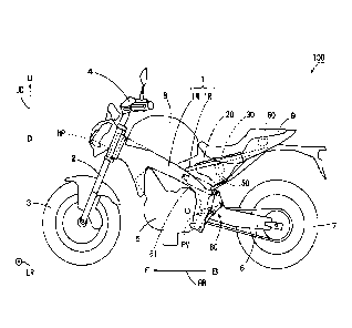
Fig. 1 is a side view of a motorcycle according to one embodiment of the
present
teaching;
Fig. 2 is a schematic perspective view for explaining the attachment state of
an
inertial sensor in the motorcycle;
Fig. 3 is a plan view of a battery case of Fig. 2;
Fig. 4 is a plan view showing the positional relationship among various
constituent
elements stored in the battery case of Fig. 2;
Fig. 5 is a schematic transparent side view of the rear half of the vehicle
for
explaining the positional relationship between a shock absorbing mechanism and
a rear
wheel, and the battery case;
Fig. 6 is a schematic transparent side view of the rear half of the vehicle
for
explaining the positional relationship between the shock absorbing mechanism
and rear
wheel, and the battery case;
Fig. 7 is a schematic transparent side view for explaining the details of the
state of a
battery and an inertial sensor being fixed in the battery case;
Fig. 8 is a schematic transparent perspective view for explaining the details
of the
state of the battery and the inertial sensor being fixed in the battery case;
and
Fig. 9 is a perspective view and a partial cross sectional view for explaining
the
details of the state of the battery case being fixed to a rear frame.
DESCRIPTION OF THE PREFERRED EMBODIMENTS
A straddled vehicle according to one embodiment of the present teaching will
be
described below with reference to the drawings. A motorcycle will be described
as one
example of the straddle vehicle.
[1] Schematic Configuration of Motorcycle
Fig. 1 is a side view of the motorcycle according to the one embodiment of the
present teaching. Fig. 1 shows the motorcycle 100 standing up to be
perpendicular to the
road surface. In each of Fig. 1 and subsequent given diagrams, a front-and-
rear direction
FB, a left-and-right direction LR and a top-and-bottom direction UD of the
motorcycle 100
are indicated by arrows. The direction in which an arrow is directed in the
front-and-rear
direction FB is referred to as forward, and its opposite direction is referred
to as rearward.
CA 3087548 2020-07-16
7
Further, the direction in which an arrow is directed in the left-and-right
direction LR is
referred to as leftward, and its opposite direction is referred to as
rightward. Further, the
direction in which an arrow is directed in the top-and-bottom direction UD is
referred to as
upward, and its opposite direction is referred to as downward. In each of Fig.
1 and
subsequent given diagrams, forward, rearward, leftward, rightward, upward and
downward
are indicated by reference characters F, B, L, R, U and D, respectively.
The motorcycle 100 of Fig. 1 includes a metallic body frame 1. The body frame
1
includes a main frame 1M and a rear frame 1R. The front end of the main frame
1M
constitutes a head pipe HP. The main frame 1M is formed to extend rearwardly
and
downwardly from the head pipe HP. The rear frame 1R is attached to the main
frame 1M
so as to extend rearwardly and slightly upwardly from the rear end and the
vicinity of the
rear end of the main frame 1M.
A front fork 2 is provided at the head pipe HP to be swingable in the left-and-
right
direction LR. A front wheel 3 is rotatably supported at the lower end of the
front fork 2. A
handle 4 is provided at the upper end of the front fork 2.
The main frame 1M supports an engine 5 at a position farther downward than the
head pipe HP. A fuel tank 8 is provided to be located upwardly of the engine 5
and
rearwardly of the head pipe HP. A seat 9 is provided rearwardly of the fuel
tank 8. The fuel
tank 8 is supported by the main frame 1M and located above the main frame 1M.
A seat 9
is mainly supported by the rear frame 1R and is located above the rear frame
1R.
A rear arm 6 is provided to extend rearwardly from the lower rear end of the
main
frame 1M. The rear arm 6 is supported by the main frame 1M via a pivot shaft
PV. A rear
wheel 7 is rotatably supported at the rear end of the rear arm 6. The rear
wheel 7 is rotated
by the motive power generated by the engine 5 as a drive wheel.
A shock-absorbing mechanism 80 for absorbing shock transmitted from the rear
wheel 7 to the rear arm 6 during traveling of the vehicle is provided in the
rear half of the
main frame 1M. The shock-absorbing mechanism 80 includes a rear suspension 81.
Details of the shock-absorbing mechanism 80 will be described below.
A resin battery case 20 is fixed to the rear frame 1R so as to be located
below the
seat 9. The battery case 20 stores a battery 30 for supplying electrical power
to an
electrical system of the motorcycle 100. Further, the battery case 20 stores
an IMU (Inertial
Measurement Unit) 50. In the following description, the IMU is referred to as
an inertial
sensor.
The inertial sensor 50 includes an acceleration sensor, and measures
acceleration
exerted on the motorcycle 100 in directions of three axes orthogonal to one
another.
Further, the inertial sensor 50 includes a gyro sensor, and measures an
angular velocity
generated around each of the above-mentioned three axes as a traveling state
of the
motorcycle 100. Further, the inertial sensor 50 outputs the results of these
measurements.
CA 3087548 2020-07-16
8
=
An ECU (Electronic Control Unit) 60 is further provided below the seat 9. The
ECU
60 may or may not be stored in the battery case 20. The ECU 60 controls
various
operation elements in the motorcycle 100 based on the results of various
measurements
output from the inertial sensor 50.
For example, the motorcycle 100 according to the present embodiment is
provided
with an ABS (Antilock Brake System). The ABS is mainly constituted by a master
cylinder,
a caliper and a hydraulic unit. In this case, the ECU 60 controls an operation
of the
hydraulic unit 70 (see Fig. 4, described below) of the ABS based on the
results of various
measurements output from the inertial sensor 50. Thus, the ABS is
appropriately controlled
according to a state of the vehicle.
[2] Attachment State of Inertial Sensor 50 in Motorcycle 100
Fig. 2 is a schematic perspective view for explaining the attachment state of
the
inertial sensor 50 in the motorcycle 100, and Fig. 3 is a plan view of the
battery case 20 of
Fig. 2. In Fig. 2, in order to facilitate understanding of the positional
relationship between
the battery 30 and the inertial sensor 50, the battery 30 is lightly hatched
and the inertial
sensor 50 is darkly hatched. In the present embodiment, the battery 30 has a
substantially
rectangular parallelepiped shape extending in the left-and-right direction LR,
and has a
relatively large weight (about five kilograms). On the other hand, the
inertial sensor 50 has
a substantially rectangular parallelepiped shape that is flat in the top-and-
bottom direction
UD, and has a sufficiently small weight (about several dozen grams) as
compared to the
battery 30.
As shown in Fig. 2, the rear frame 1R includes a pair of left and right upper
rails 11
and a pair of left and right lower rails 12. The left and right upper rails 11
are formed to be
arranged in the left-and-right direction LR and extend in parallel to the
front-and-rear
direction FB, and their rear ends are connected to each other. On the other
hand, the left
and right lower rails 12 are formed to extend from the vicinity of the rear
ends of the left and
right upper rails 11 while being curved downwardly and forwardly. With such a
configuration, the rear frame 1R substantially has a U-shape in a plan view.
As indicated by thick dotted lines in Fig. 2, upper fixing portions 19L, 19R
are
formed in substantially the center portion in the front-and-rear direction FB
of the left upper
rail 11 and substantially the center portion in the front-and-rear direction
FB of the right
upper rail 11. Holes into which bolts can be inserted are formed in the upper
fixing portions
19L, 19R.
Front ends 11e of the left and right upper rails 11 and front ends 12e of the
left and
right lower rails 12 are respectively connected to and fixed to the main frame
1M of Fig. 1.
The portion of the left lower rail 12 that is located at a position farther
rearward than the
front end 12e by a certain distance is coupled to the portion of the right
lower rail 12 that is
located at a position farther rearward than the front end 12e by a certain
distance by a
CA 3087548 2020-07-16
9
=
metallic strip-shaped coupling plate 13. Two lower fixing portions 13a
respectively
corresponding to left and right lower fixing portions 28L, 28R (Fig. 3),
described below, of
the battery case 20 are formed in the strip-shaped coupling plate 13. Holes
into which bolts
can be inserted are formed in the two lower fixing portions 13a.
As shown in Figs. 2 and 3, the battery case 20 has a bottom wall 21, a left
wall 22
and a right wall 23. The bottom wall 21 has a rectangular shape extending in
the front-and-
rear direction FB in a plan view of the vehicle. The left wall 22 is formed to
extend
upwardly from the left edge of the bottom wall 21. The right wall 23 is formed
to extend
upwardly from the right edge of the bottom wall 21.
The substantially central portion of the bottom wall 21 protrudes farther
downwardly
than the rest of the bottom wall 21. The substantially central portion of the
bottom wall 21
is referred to as a bottom portion 27 of the battery case 20. With such a
configuration, the
peripheral portion of the bottom portion 27 in the bottom wall 21 functions as
a rib for
improving the rigidity of the battery case 20. Thus, the battery case 20 has
high rigidity
despite being formed of resin. In Fig. 3, the bottom portion 27 of the battery
case 20 is
indicated by a thick one-dot and dash line.
As shown in Fig. 3, two lower fixing portions 28L, 28R, an inertial sensor
fixing
portion 29 and a wire fixing portion 27w are formed in the bottom portion 27
of the battery
case 20. The two lower fixing portions 28L, 28R are formed to be arranged in
the left-and-
right direction LR to be spaced apart from each other. A through hole h0 is
formed in each
of the lower fixing portions 28L, 28R. The inertial sensor fixing portion 29
has a flat
rectangular upper surface. The upper surface of the inertial sensor fixing
portion 29 is used
as a fixing surface for fixing the inertial sensor 50. In the inertial sensor
fixing portion 29,
four through holes h1 are formed.
Further, the front half of the inertial sensor fixing portion 29 is formed to
be located
between the two lower fixing portions 28L, 28R. The wire fixing portion 27w is
formed at a
position in the vicinity of the inertial sensor fixing portion 29 and adjacent
to the right lower
fixing portion 28R of the two lower fixing portions 28L, 28R. Details of the
wire fixing
portion 27w will be described below.
A battery fixing portion 24L is formed between the left wall 22 and the bottom
portion 27 in the bottom wall 21 in the plan view of the vehicle. Further, a
battery fixing
portion 24R is formed between the right wall 23 and the bottom portion 27 in
the bottom
wall 21 in the plan view of the vehicle. The battery fixing portions 24L, 24R
have flat strip-
shaped upper surfaces. The heights of the upper surfaces of the battery fixing
portions
24L, 24R in the top-and-bottom direction UD are equal to each other. Step
portions SL, SR
are formed at the rear ends of the battery fixing portions 24L, 24R,
respectively.
A sheet metal fixing portion 25 is formed rearwardly of the left battery
fixing portion
24L in the bottom wall 21 as indicated by a dotted line in Fig. 3. The sheet
metal fixing
CA 3087548 2020-07-16
10
=
portion 25 has a flat rectangular upper surface. The upper surface of the
sheet metal fixing
portion 25 is used as a fixing surface for fixing a base sheet metal 230
(Figs. 7 and 8)
described below. Two through holes h2 are formed in the sheet metal fixing
portion 25.
An upper fixing portion 26L is formed in the vicinity of the rear end of the
left wall 22
so as to project leftwardly from the upper end of the left wall 22 by a
certain distance.
Further, an upper fixing portion 26R is formed in the vicinity of the rear end
of the right wall
23 so as to project rightwardly from the upper end of the right wall 23 by a
certain distance.
A through hole h3 is formed in each of the upper fixing portions 26L, 26R.
As indicated by a thick two-dots and dash arrow in Fig. 2, when the battery
case 20
is attached to the rear frame 1R, the left and right lower fixing portions
28L, 28R of the
battery case 20 are respectively connected to the two lower fixing portions
13a of the strip-
shaped coupling plate 13 with bolts and nuts. Further, the left and right
upper fixing
portions 26L, 26R of the battery case 20 are connected to the left and right
upper fixing
portions 19L, 19R of the rear frame 1R with bolts and nuts, respectively.
Thus, the battery
case 20 is fixed to the rear frame 1R.
The inertial sensor 50 has an outer shape that is equal to or smaller than
that of the
inertial sensor fixing portion 29 of Fig. 4 in a plan view, and is fixed to
the bottom portion 27
of the battery case 20 as indicated by a thick dotted arrow in Fig. 2. More
specifically, the
inertial sensor 50 is fixed to the inertial sensor fixing portion 29 (Fig. 3)
of the bottom
portion 27.
The dimension of the battery 30 in the longitudinal direction (the left-and-
right
direction LR in which the battery 30 extends) is larger than the distance
between the left
and right battery fixing portions 24L, 24R and is smaller than the distance
between the left
and right walls 22, 23 in Fig. 3.
The battery 30 is fixed in the battery case 20 such that both ends of the
battery 30
in the longitudinal direction are respectively supported on the left and right
battery fixing
portions 24L, 24R as indicated by a thick one-dot and dash arrow in Fig. 2.
The inertial
sensor 50 and the battery 30 being fixed in the battery case 20 are shown in
the balloon in
Fig. 2.
Fig. 4 is a plan view showing the positional relationship among various
constituent
elements stored in the battery case 20 of Fig. 2. In Fig. 4, the main frame 1M
and the rear
frame 1R are hatched with two types of lines in different directions to
facilitate
understanding of the connection state among the main frame 1M, the rear frame
1R and
the battery case 20. Further, the battery case 20 is indicated by a dotted
pattern. Further,
in Fig. 4, the battery 30 and the inertial sensor 50 fixed in the battery case
20 are indicated
by thick one-dot and dash lines.
As shown in the balloon in Fig. 2, and Fig. 4, the battery 30 is fixed in the
vicinity of
the fixing portion (the bottom portion 27) of the inertial sensor 50 in the
battery case 20 so
CA 3087548 2020-07-16
11
=
as to overlap with at least part of the inertial sensor 50 in the plan view of
the vehicle.
=
Thus, because the battery 30 has a relatively large weight, even in a case
where vibration
is transmitted from the body frame 1 to the battery case 20 during traveling
of the vehicle,
vibration of the bottom portion 27 is suppressed due to the weight of battery
30. The
vibration transmitted from the body frame 1 to the battery case 20 during
traveling of the
vehicle includes vibration generated from the engine 5, vibration generated in
the front
wheel 3, vibration generated in the rear wheel 7 and the like.
Further, since the above-mentioned battery case 20 is made of resin, the parts
other than the bottom portion 27 and its vicinity have a certain degree of
flexibility.
Therefore, part of the vibration transmitted from the body frame 1 to the
battery case 20
during traveling of the vehicle is absorbed by the battery case 20. Therefore,
the vibration
transmitted to the inertial sensor 50 during traveling of the vehicle is
reduced.
Here, the battery 30 of Fig. 4 is fixed to the battery case 20 at a position
farther
upward than the inertial sensor 50 so as to overlap with the entire inertial
sensor 50 in the
.. plan view of the vehicle. With such a configuration, in order to access the
inertial sensor 50
from outside of the motorcycle 100, it is necessary to remove the seat 9 and
the battery 30
from the body frame 1 in this order. Therefore, in the motorcycle 100
according to the
present embodiment, the difficulty in accessing the inertial sensor 50 from
outside of the
motorcycle 100 is increased. As a result, the theft of the inertial sensor 50
is prevented,
and a decrease in measurement accuracy caused by the user carelessly touching
the
inertial sensor 50 is suppressed.
Further, in the motorcycle 100, the inertial sensor 50 is arranged so as to
overlap
with a vehicle central axis CL of Fig. 4 that extends in the front-and-rear
direction FB in the
plan view of the vehicle. In this case, the inertia of the motorcycle 100 is
measured more
accurately by the inertial sensor 50.
In the present embodiment, the hydraulic unit 70 and an electrical component
71
are fixed in the battery case 20 in addition to the battery 30 and the
inertial sensor 50 as
indicated by thick two-dots and dash lines in Fig. 4. The hydraulic unit 70
constitutes part
of the ABS provided in the motorcycle 100. The electrical component 71
includes a fuse
and a connector that constitute part of the electrical system of the
motorcycle 100. In this
manner, part of a supply system for liquid (such as brake fluid or oil) and
part of the
electrical system in the motorcycle 100 are stored in the battery case 20 in
addition to the
battery 30 and the inertial sensor 50.
In the example of Fig. 4, the hydraulic unit 70 has a weight that is
sufficiently larger
than that of the inertial sensor 50, and is fixed in the battery case 20 so as
to be adjacent to
the battery 30. Therefore, the members having relatively large weight such as
the battery
30 and the hydraulic unit 70 are gathered in the bottom portion 27 and its
vicinity in the
battery case 20. Thus, the vibration generated in the vicinity of the inertial
sensor 50 in the
CA 3087548 2020-07-16
12
battery case 20 is reduced by the weight of the battery 30 and the hydraulic
unit 70.
=
Further, because the hydraulic unit 70 is stored in the battery case 20, an
increase in height
of the seat 9 caused by provision of the hydraulic unit 70 outside of the
battery case 20 is
suppressed.
[3] Positional Relationship Among Shock Absorbing Mechanism 80, Rear Wheel 7
and Battery Case 20
Figs. 5 and 6 are schematic transparent side views of the rear half of the
vehicle for
explaining the positional relationship among the shock absorbing mechanism 80,
the rear
wheel 7 and the battery case 20. In Figs. 5 and 6, the battery case 20, the
battery 30 and
the inertial sensor 50 are indicated by thick one-dot and dash lines.
Meanwhile, parts of
the structure including the rear arm 6, the shock absorbing mechanism 80 and
the rear
wheel 7 of the motorcycle 100 are indicated by solid lines.
As shown in Fig. 5, the shock absorbing mechanism 80 includes a rear
suspension
81, a first link member 82 and a second link member 83. The rear suspension 81
is
provided at a position farther forward than the rear wheel 7 to extend
obliquely downwardly
toward a position rearward of the vehicle.
The front end of the rear suspension 81 is connected to a portion in the
vicinity of
the fuel tank 8 in the main frame 1M. The first link member 82 is connected to
the rear end
of the rear suspension 81. The first link member 82 is further connected to
part of the rear
arm 6 and connected to the second link member 83. The second link member 83 is
further
connected to the lower end of the main frame 1M.
In regard to the connection portion between the main frame 1M and the rear
suspension 81, the connection portion between the rear suspension 81 and the
first link
member 82, and the connection portion between the first link member 82 and the
rear arm
6, one member and the other member are rotatable relative to each other about
an axis
parallel to the left-and-right direction LR. Further, in each of the
connection portion
between the first link member 82 and the second link member 83 and the
connection
portion between the second link member 83 and the main frame 1M, one member
and the
other member are rotatable with relative to each other about an axis parallel
to the left-and-
right direction LR.
With the above-mentioned configuration, part of the rear arm 6 is supported at
the
main frame 1M via the rear suspension 81 so as to be swingable in the top-and-
bottom
direction of the vehicle. Thus, when shock that is generated in the rear wheel
7 is
transmitted to the rear suspension 81, the rear suspension 81 absorbs the
transmitted
shock.
Fig. 5 shows the state of the rear half of the vehicle when shock is not
generated in
the rear wheel 7, that is, the state of the rear half of the vehicle when the
rear suspension
81 is not absorbing shock. In the following description, the state of the
vehicle shown in
CA 3087548 2020-07-16
13
=
Fig. 5 is referred to as a normal state. On the other hand, Fig. 6 shows the
state of the rear
half of the vehicle when the rear suspension 81 is most contracted by
absorbing the shock
generated in the rear wheel 7. In the following description, the state of the
vehicle shown in
Fig. 6 is referred to as a maximum shock state.
In Fig. 6, the state of the rear arm 6, the shock absorbing mechanism 80 and
the
rear wheel 7 in the normal state is further indicated by dotted lines. As
shown in Figs. 5
and 6, during traveling of the motorcycle 100, the rear arm 6 and the rear
wheel 7 rotate
(swing) in the top-and-bottom direction UD about the pivot shaft PV according
to the
magnitude of the shock generated between the road surface and the rear wheel
7.
Here, the battery case 20 is provided not to overlap with the rear suspension
81 and
the rear wheel 7 in a side view of the vehicle when the motorcycle 100 is in
the maximum
shock state. Further, the battery case 20 is provided such that the bottom
portion 27
projects toward a position between the rear suspension 81 and the rear wheel 7
in the
front-and-rear direction FB in the side view of the vehicle.
With the above-mentioned configuration, the inertial sensor 50 is fixed to the
bottom
portion 27 of the battery case 20 so as to be located in a dead space outside
of the range
of motion of the rear suspension 81 and the range of motion of the rear wheel
7 in the side
view of the vehicle. Thus, the dead space in the motorcycle 100 is effectively
utilized as a
space in which the inertial sensor 50 is provided. Therefore, the inertial
sensor 50 can be
arranged in the battery case 20 without an increase in height of the seat 9.
[4] Details of Fixed State of Battery 30 and Inertial Sensor 50
Fig. 7 is a schematic transparent side view for explaining the details of the
fixed
state of the battery 30 and the inertial sensor 50 in the battery case 20.
Fig. 8 is a
schematic transparent perspective view for explaining the details of the fixed
state of the
battery 30 and the inertial sensor 50 in the battery case 20. In Figs. 7 and
8, the shape of
part of the battery case 20 is indicated by dotted lines.
As shown in Fig. 7, rubber grommets gr are fitted into the four through holes
hl
(Fig. 3) of the inertial sensor fixing portion 29 at the bottom portion 27 of
the battery case
20. In Fig. 7, the grommets gr are hatched. The inertial sensor 50 is
connected to the
inertial sensor fixing portion 29 via the four grommets gr with four bolts and
four nuts. In
this manner, because the inertial sensor 50 is fixed to the inertial sensor
fixing portion 29
via the plurality of grommets gr, transmission of the vibration generated in
the battery case
20 during traveling of the vehicle to the inertial sensor 50 is suppressed.
Thus, the inertia
of the motorcycle 100 can be measured with high accuracy.
In the battery case 20, a metallic fixing mechanism 200 configured to be
capable of
fixing the battery 30 in the battery case 20 and detaching the battery 30 from
the battery
case 20 is provided. As shown in Figs. 7 and 8, the fixing mechanism 200
includes a first
fixing member 210, a second fixing member 220 and a base sheet metal 230.
CA 3087548 2020-07-16
14
=
In the present embodiment, a bending process is performed on one piece of hard
wire, and one end and the other end of the wire are connected to each other,
for example,
whereby the first fixing member 210 is fabricated. The first fixing member 210
of the
present example is formed so as to delineate a strip having a certain width
and extending in
one direction. The first fixing member 210 has a first end 211 and a second
end 212.
A punching process, a bending process and the like are performed on one piece
of
sheet metal, for example, whereby each of the second fixing member 220 and the
base
sheet metal 230 are fabricated. The second fixing member 220 has a third end
221 and a
fourth end 222. The base sheet metal 230 has a fifth end 231 and a sixth end
232.
The first end 211 of the first fixing member 210 is connected to the wire
fixing
portion 27w of the battery case 20. The second end 212 of the first fixing
member 210 is
connected to the third end 221 of the second fixing member 220. Here, the
connection
portion between the second end 212 and the third end 221 forms a hinge. Thus,
the
second fixing member 220 is rotatable about an axis parallel to the left-and-
right direction
LR through the second end 212 of the first fixing member 210.
The sixth end 232 of the base sheet metal 230 is fixed to the sheet metal
fixing
portion 25 with a bolt. In this state, the fifth end 231 of the base sheet
metal 230 is located
above the sheet metal fixing portion 25.
The second fixing member 220 rotates about the second end 212 of the first
fixing
member 210, whereby the fourth end 222 of the second fixing member 220 and the
fifth
end 231 of the base sheet metal 230 come into contact with each other or move
away from
each other. Further, the fourth end 222 and the fifth end 231 are configured
to be
connectable to each other with bolts and nuts while being in contact with each
other.
Here, the battery 30 has a first surface 31 that faces mainly forwardly in the
battery
case 20 and a second surface 32 that mainly faces upwardly in the battery case
20.
Further, the battery 30 has a third surface 33 that mainly faces downwardly in
the battery
case 20, and a fourth surface 34 that mainly faces rearwardly in the battery
case 20.
When fixing the battery 30 in the battery case 20, the battery 30 is placed on
the left
and right battery fixing portions 24L, 24R (Fig. 3). At this time, part of the
third surface 33
abuts against the battery fixing portions 24L, 24R, and part of the fourth
surface 34 abuts
against the left and right steps SL, SR (Fig. 3), whereby the battery 30 is
temporarily
positioned in the battery case 20. Further, the first fixing member 210
extends upwardly
from the wire fixing portion 27w along the first surface 31 of the battery 30.
In this state, the second fixing member 220 rotates about the second end 212
of the
first fixing member 210, thereby being able to be in close proximity to or
spaced apart from
the second surface 32 of the battery 30 as indicated by the thick one-dot and
dash arrow in
Figs. 7 and 8.
Rubber shock buffering members sg are provided on part of the second fixing
CA 3087548 2020-07-16
15
=
member 220 so as to come into contact with the second surface 32 due to the
second
fixing member 220 being in close proximity to the second surface 32. With the
second
fixing member 220 supported on the second surface 32 of the battery 30 via the
shock
buffering members sg, the fourth end 222 of the second fixing member 220
overlaps with
the fifth end 231 of the base sheet metal 230. As such, the fourth end 222 and
the fifth end
231 are connected to each other with a bolt and a nut, whereby the battery 30
is fixed in the
vicinity of the bottom portion 27 in the battery case 20.
On the other hand, when the battery 30 is removed from the battery case 20,
the
bolt and nut connecting the fourth end 222 to the fifth end 231 are detached.
Thus, it is
possible to remove the battery 30 from the battery case 20 by detaching the
second fixing
member 220 from the second surface 32 of the battery 30.
With the above-mentioned configuration, the battery 30 can be easily and
firmly
fixed in the battery case 20 by the fixing mechanism 200. Thus, generation of
vibration in
the bottom portion 27 of the battery case 20 due to the movement of the
battery 30 with
respect to the battery case ,20 during traveling of the vehicle is suppressed.
As a result, the
inertia of the motorcycle 100 can be measured by the inertial sensor 50 with
high accuracy.
Further, the battery 30 fixed to the battery case 20 can be easily removed.
Therefore, the
battery 30 can be easily replaced.
The inertial sensor 50 according to the present embodiment has a flat
attachment
surface for attaching the inertial sensor 50 to the upper surface of the
inertial sensor fixing
portion 29. In the present embodiment, as shown in Fig. 7, the inertial sensor
50 is fixed in
the battery case 20 such that the angle 6 formed by the attachment surface of
the inertial
sensor 50 and a horizontal plane RP does not exceed 15 . In this manner,
because the
inertial sensor 50 is not inclined with respect to the horizontal plane RP by
more than 15 ,
the inertia of the motorcycle 100 can be measured with high accuracy. In order
to measure
the inertia of the motorcycle 100 with higher accuracy, it is preferable that
the angle @
formed by the attachment surface of the inertial sensor 50 and the horizontal
plane RP is
equal to or smaller than 12 .
As shown in Fig. 7, the inertial sensor fixing portion 29 and the battery
fixing
portions 24L, 24R are formed such that the distance ds between the battery 30
and the
inertial sensor 50 is smaller than half of the thickness of the battery 30 in
the top-and-
bottom direction UD. In this case, the distance between the inertial sensor
fixing portion 29
and each of the battery fixing portions 24L, 24R is sufficiently small, so
that the vibration of
the inertial sensor 50 is more easily suppressed by the weight of the battery
30.
[5] Details of Fixed State of Battery Case 20 to Rear Frame 1R
Fig. 9 shows a perspective view and partial cross-sectional views for
explaining the
details of the fixed state of the battery case 20 to the rear frame 1R. In
Fig. 9, an external
perspective view shows the battery case 20 being fixed to the rear frame 1R.
Further, in
CA 3087548 2020-07-16
16
=
Fig. 9, the cross section of the connection portion between the upper fixing
portion 26L of
the battery case 20 and the upper fixing portion 19L of the rear frame 1R is
shown in the
balloon BA1. Further, the cross section of the connection portion between the
lower fixing
portion 28L of the battery case 20 and the left lower fixing portion 13a of
the strip-shaped
coupling plate 13 is shown in the balloon BA2.
As shown in the balloon BA1 in Fig. 9, a grommet gr is fitted into the through
hole
h3 in the upper fixing portion 26L of the battery case 20. Thus, the upper
fixing portion 26L
of the battery case 20 is positioned on the upper fixing portion 19L of the
rear frame 1R via
the grommet gr. In this state, the upper fixing portion 26L of the battery
case 20 and the
upper fixing portion 19L of the rear frame 1R are connected to each other with
a bolt BT
and a nut NT. The structure of the connection portion between the upper fixing
portion 26R
of the battery case 20 and the upper fixing portion 19R of the rear frame 1R
is the same as
that of the connection portion between the upper fixing portion 26L of the
battery case 20
and the upper fixing portion 19L of the rear frame 1R.
As shown in the balloon BA2 in Fig. 9, a grommet gr is fitted into the through
hole
h0 in the lower fixing portion 28L of the battery case 20. Thus, the lower
fixing portion 28L
of the battery case 20 is positioned on the left lower fixing portion 13a of
the strip-shaped
coupling plate 13 via the grommet gr. In this state, the lower fixing portion
28L of the
battery case 20 and the left lower fixing portion 13a of the strip-shaped
coupling plate 13
are connected to each other with a bolt BT and a nut NT. The structure of the
connection
portion between the lower fixing portion 28R of the battery case 20 and the
right lower
fixing portion 13a of the strip-shaped coupling plate 13 is the same as that
of the
connection portion between the lower fixing portion 28L of the battery case 20
and the left
lower fixing portion 13a of the strip-shaped coupling plate 13.
With the above-mentioned configuration, because the battery case 20 is fixed
to the
rear frame 1R via the plurality of grommets gr, transmission of vibration
generated in the
rear frame 1R during traveling of the vehicle to the battery case 20 is
suppressed. Thus,
the inertia of the motorcycle 100 can be measured with higher accuracy.
[6] Effects
In the above-described motorcycle 100, the inertial sensor 50 is fixed to the
bottom
portion 27 of the battery case 20. Thus, the dead space that is outside of the
range of
motion of the rear suspension 81 with respect to the body frame 1 and the
range of motion
of the rear wheel 7 is effectively used as an installation space for the
inertial sensor 50.
Therefore, the inertial sensor 50 can be arranged in the battery case 20
without an increase
in height of the seat 9.
Further, with the above-mentioned configuration, the battery 30 is fixed to
the
battery case 20 at a position above the inertial sensor 50 so as to overlap
with the inertial
sensor 50 in the plan view of the vehicle. In this case, the portion to which
the battery 30 is
CA 3087548 2020-07-16
17
=
attached is in close proximity to the portion to which the inertial sensor 50
is attached in the
battery case 20. Thus, even in a case where vibration is transmitted from the
body frame 1
to the battery case 20 during traveling of the vehicle, vibration of the
bottom portion 27 of
the battery case 20 is suppressed by the weight of the battery 30. Further,
since being
made of resin, the above-mentioned battery case 20 absorbs part of the
vibration
transmitted from the body frame 1. Therefore, the vibration generated in the
inertial sensor
50 is reduced.
Further, with the above-mentioned configuration, the inertial sensor 50 is
fixed to
the inertial sensor fixing portion 29 of the battery case 20. Further, the
battery 30 and the
seat 9 are present above the inertial sensor 50. Thus, the difficulty in
accessing the inertial
sensor 50 from outside of motorcycle 100 is increased. Further, because the
inertial
sensor 50 is provided inside of the battery case 20, splashed rainwater or
scattered dust
outside of the motorcycle 100 during traveling of the vehicle is prevented
from adhering to
the inertial sensor 50.
As a result, an increase in size of the vehicle due to provision of the
inertial sensor
50 is suppressed while high detection accuracy of inertia by the inertial
sensor 50 is
maintained.
[7] Other Embodiments
(a) While the inertial sensor 50 is fixed to the battery case 20 via the
plurality of
grommets gr in the above-mentioned embodiment, the present teaching is not
limited to
this. The inertial sensor 50 may be directly fixed to the battery case 20.
(b) While the battery case 20 is fixed to the rear frame 1R via the plurality
of
grommets gr in the above-mentioned embodiment, the present teaching is not
limited to
this. The battery case 20 may be directly fixed to the rear frame 1R.
(c) While the battery 30 is fixed to the battery case 20 with use of the
metallic fixing
mechanism 200 in the above-mentioned embodiment, the present teaching is not
limited to
this. The battery 30 may be fixed to the battery case 20 with a strip-shaped
member made
of cloth or rubber, or the like, Alternatively, the battery 30 may be directly
fixed to the
battery case 20 with a bolt.
(d) While the hydraulic unit 70 is fixed in the battery case 20 so as to be
adjacent to
the battery 30 in the front-and-rear direction FB in the above-mentioned
embodiment, the
present teaching is not limited to this. The hydraulic unit 70 may be fixed in
the battery
case 20 so as to be adjacent to the battery 30 in the left-and-right direction
LR.
(e) While the hydraulic unit 70 is fixed in the battery case 20 in the above-
mentioned embodiment, the hydraulic unit 70 may be provided outside of the
battery case
20.
(f) The degree to which the rear suspension 81 is inclined with respect to the
horizontal plane is not limited to the examples of Figs. 5 and 6 in the above-
mentioned
CA 3087548 2020-07-16
18
=
embodiment. The rear suspension 81 may be provided at a position farther
forward than
the rear wheel 7 to extend obliquely downwardly toward a position rearward of
the vehicle.
Therefore, the rear suspension 81 may be provided such that the angle between
the
direction in which the rear suspension 81 extends and the horizontal plane is
smaller than
those of the examples of Figs. 5 and 6. Alternatively, the rear suspension 81
may be
provided such that the angle between the direction in which the rear
suspension 81 extends
and the horizontal plane is larger than those of the examples of Figs. 5 and
6.
(g) While the above-mentioned embodiment is an example in which the present
teaching is applied to the motorcycle, the present teaching is not limited to
this. The
present teaching may be applied to another straddled vehicle such as a four-
wheeled
automobile, a motor tricycle or an ATV (All Terrain Vehicle).
[8] Correspondences between Constituent Elements in Claims and Parts in
Preferred Embodiments
In the following paragraphs, non-limiting examples of correspondences between
various elements recited in the claims below and those described above with
respect to
various preferred embodiments of the present teaching are explained.
In the above-mentioned embodiment, the body frame 1, the main frame 1M and the
rear frame R1 are examples of a body frame, the seat 9 is an example of a
seat, the battery
30 is an example of a battery, the inertial sensor 50 is an example of an
inertia
measurement device, the battery case 20 is an example of a battery case, the
rear arm 6 is
an example of a rear arm, the rear wheel 7 is an example of a drive wheel, the
rear
suspension 81 is an example of a rear suspension, the bottom portion 27 of the
battery
case 20 is an example of a bottom portion of a battery case.
Further, the motorcycle 100 is an example of a straddled vehicle, the
hydraulic unit
70 is an example of a hydraulic unit, the grommet gr is an example of first
and second
shock buffering members, the vehicle central axis CL of Fig. 4 is an example
of a vehicle
central axis, the fixing mechanism 200 is an example of a fixing mechanism,
the first
surface 31 of the battery 30 is an example of a first surface, and the second
surface 32 of
the battery 30 is an example of a second surface.
Further, the first end 211 is an example of a first end, the second end 212 is
an
example of a second end, the first fixing member 210 is an example of a first
fixing
member, the third end 221 is an example of a third end, the fourth end 222 is
an example
of a fourth end, the second fixing member 220 is an example of a second fixing
member,
the hydraulic unit 70 is an example of an operating element, and the ECU 60 is
an example
of a controller.
CA 3087548 2020-07-16