Note: Descriptions are shown in the official language in which they were submitted.
CA 03087769 2020-07-06
WO 2019/136437
PCT/US2019/012691
TREATMENT OF PULMONARY CANCERS USING AN ELECTRONIC BREATH
ACTUATED DROPLET DELIVERY DEVICE
RELATED APPLICATIONS
[0001] The
present application claims benefit under 35 U.S.C. 119 of U.S.
Provisional Patent Application No. 62/614,858, filed January 8, 2018, entitled
"TREATMENT OF PULMONARY CANCERS USING AN ELECTRONIC BREATH
ACTUATED DROPLET DELIVERY DEVICE", and U.S. Provisional Patent Application
No. 62/621,957, filed January 25, 2018, entitled "TREATMENT OF PULMONARY
CANCERS USING AN ELECTRONIC BREATH ACTUATED DROPLET DELIVERY
DEVICE", the contents of which are each herein incorporated by reference in
their entireties.
FIELD OF THE INVENTION
[0002]
This disclosure relates to methods for the treatment of pulmonary cancers
using droplet delivery devices and more specifically to droplet delivery
devices for the
delivery of fluids to the pulmonary system.
BACKGROUND OF THE INVENTION
[0003]
Lung cancer is the leading cause of cancer death in the United States killing
an
estimated 160,000 people annually with approximately 200,000 newly diagnosed
in 2010
alone. The number of deaths caused by lung cancer exceeds that of colon,
breast and prostate
cancer combined. Lung cancer is associated with a dismal 5-year survival rate
of 15% due to
the fact that the majority of patients are diagnosed in the late stages of
disease after metastasis
has occurred. Human lung cancer is comprised of two main histopathologic
groups, non-
small cell (NSCLC) and small cell lung cancer (SCLC). Approximately 80% of
lung cancers
are NSCLC, originating from lung epithelial cells. NSCLC is further subdivided
into adeno,
squamous, and large cell subtypes. Adenocarcinomas arise in the periphery and
comprise
¨40% of all NSCLC.
[0004]
While many treatments have been proposed for lung cancer, it would be
desirable to develop improved treatments with reduced side effects.
SUMMARY OF THE INVENTION
[0005] In
one aspect, this disclosure relates to a method for treating pulmonary cancer
in a subject in need thereof by delivering a therapeutic agent as an ejected
stream of droplets
in a respirable range to the pulmonary system oft. The method may comprise:
(a) generating
an ejected stream of droplets via a breath actuated droplet delivery device of
the disclosure,
1
CA 03087769 2020-07-06
WO 2019/136437
PCT/US2019/012691
wherein at least about 50% of the ejected stream of droplets have an average
ejected droplet
diameter of less than about 6 um; and (b) delivering the ejected stream of
droplets to the
pulmonary system of the subject such that at least about 50% of the mass of
the ejected
stream of droplets is delivered in a respirable range to the pulmonary system
of a subject
during use to thereby treat the pulmonary cancer.
[0006] In
certain embodiments, the pulmonary cancer may be a primary, secondary or
metastatic pulmonary cancer. In other embodiments, the pulmonary cancer may be
non-small
cell lung cancer (NSCLC) or small cell lunch cancer (SCLC). The therapeutic
agent may
comprise a cancer therapeutic selected from chemotherapeutic agents, immune
checkpoint
inhibitors, other antibody and immune stimulating therapeutics, and various
combinations
thereof. In yet other aspects, the therapeutic agent may be delivered to the
pulmonary system
of the subject at higher concentrations, as compared to oral, systemic, or
parenteral
administration.
[0007] In
certain embodiments, the droplet delivery device of the disclosure is
configured in an in-line orientation in that the housing, its internal
components, and various
device components (e.g., the mouthpiece, air inlet flow element, etc.) are
orientated in a
substantially in-line or parallel configuration (e.g., along the airflow path)
so as to form a
small, hand-held device.
[0008] In
certain embodiments, the droplet delivery device may include: a housing; a
mouthpiece positioned at the airflow exit side of the housing; a reservoir
disposed within or
in fluid communication with the housing for receiving a volume of fluid; an
ejector
mechanism in fluid communication with the reservoir, the ejector mechanism
comprising a
piezoelectric actuator and an aperture plate, the aperture plate having a
plurality of openings
formed through its thickness and the piezoelectric actuator operable to
oscillate the aperture
plate at a frequency to thereby generate an ejected stream of droplets, at
least one differential
pressure sensor positioned within the housing; the at least one differential
pressure sensor
configured to activate the ejector mechanism upon sensing a pre-determined
pressure change
within the mouthpiece to thereby generate an ejected stream of droplets; the
ejector
mechanism configured to generate the ejected stream of droplets wherein at
least about 50%
of the droplets have an average ejected droplet diameter of less than about 6
microns, such
that at least about 50% of the mass of the ejected stream of droplets is
delivered in a
respirable range to the pulmonary system of a subject during use.
[0009] In
some aspects, the droplet delivery device further includes an air inlet flow
element positioned in the airflow at the airflow entrance of the device and
configured to
2
CA 03087769 2020-07-06
WO 2019/136437
PCT/US2019/012691
facilitate non-turbulent (i.e., laminar and/or transitional) airflow across
the exit side of
aperture plate and to provide sufficient airflow to ensure that the ejected
stream of droplets
flows through the droplet delivery device during use. In some embodiments, the
air inlet flow
element may be positioned within the mouthpiece.
[0010] In certain embodiments, the housing and ejector mechanism are
oriented such
that the exit side of the aperture plate is perpendicular to the direction of
airflow and the
stream of droplets is ejected in parallel to the direction of airflow. In
other embodiments, the
housing and ejector mechanism are oriented such that the exit side of the
aperture plate is
parallel to the direction of airflow and the stream of droplets is ejected
substantially
perpendicularly to the direction of airflow such that the ejected stream of
droplets is directed
through the housing at an approximate 90 degree change of trajectory prior to
expulsion from
the housing.
[0011] In
certain aspects, the droplet delivery device further includes a surface
tension plate between the aperture plate and the reservoir, wherein the
surface tension plate is
configured to increase contact between the volume of fluid and the aperture
plate. In other
aspects, the ejector mechanism and the surface tension plate are configured in
parallel
orientation. In yet other aspects, the surface tension plate is located within
2 mm of the
aperture plate so as to create sufficient hydrostatic force to provide
capillary flow between the
surface tension plate and the aperture plate.
[0012] In yet other aspects, the aperture plate of the droplet delivery
device comprises
a domed shape. In other aspects, the aperture plate may be formed of a metal,
e.g., stainless
steel, nickel, cobalt, titanium, iridium, platinum, or palladium or alloys
thereof. Alternatively,
the aperture plate can be formed of suitable material, including other metals
or polymers. In
certain embodiments, the aperture plate is comprised of, e.g., poly ether
ether ketone (PEEK),
polyimide, polyetherimide, polyvinylidine fluoride (PVDF), ultra-high
molecular weight
polyethylene (UHMWPE), nickel, nickel-cobalt, palladium, nickel-palladium,
platinum, or
other suitable metal alloys, and combinations thereof. In other aspects, one
or more of the
plurality of openings of the aperture plate have different cross-sectional
shapes or diameters
to thereby provide ejected droplets having different average ejected droplet
diameters.
[0013] In yet other aspects, the reservoir of the droplet delivery device
is removably
coupled with the housing. In other aspects, the reservoir of the droplet
delivery device is
coupled to the ejector mechanism to form a combination reservoir/ejector
mechanism
module, and the combination reservoir/ejector mechanism module is removably
coupled with
the housing.
3
CA 03087769 2020-07-06
WO 2019/136437
PCT/US2019/012691
[0014] In
other aspects, the droplet delivery device may further include a wireless
communication module. In some aspects, the wireless communication module is a
Bluetooth
transmitter.
[0015] In
yet other aspects, the droplet delivery device may further include one or
more sensors selected from an infer-red transmitter, a photodetector, an
additional pressure
sensor, and combinations thereof.
[0016] In
one aspect, the disclosure relates to a method for generating and delivering
a fluid as an ejected stream of droplets to the pulmonary system of a subject
in a respirable
range. The method may comprise: (a) generating an ejected stream of droplets
via a breath
actuated droplet delivery device of the disclosure, wherein at least about 50%
of the ejected
stream of droplets have an average ejected droplet diameter of less than about
6 um; and (b)
delivering the ejected stream of droplets to the pulmonary system of the
subject such that at
least about 50% of the mass of the ejected stream of droplets is delivered in
a respirable range
to the pulmonary system of a subject during use.
[0017] While multiple embodiments are disclosed, still other embodiments of
the
present disclosure will become apparent to those skilled in the art from the
following detailed
description, which shows and describes illustrative embodiments of the
disclosure. As will
be realized, the invention is capable of modifications in various aspects, all
without departing
from the spirit and scope of the present disclosure. Accordingly, the detailed
descriptions are
to be regarded as illustrative in nature and not restrictive.
BRIEF DESCRIPTION OF THE DRAWINGS
[0018]
FIGS. 1A-1B illustrate perspective views of an exemplary in-line droplet
delivery device, in accordance with embodiments of the disclosure.
[0019]
FIG. 2 is an exploded view of an in-line droplet delivery device of FIG. 1A-
1B, in accordance with embodiments of the disclosure..
[0020]
FIG. 3A-1 is a partial perspective view of a base unit of an in-line droplet
delivery device of FIG. 1A-1B, in accordance with embodiments of the
disclosure.
[0021]
FIG. 3A-2 is an exploded view of an in-line droplet delivery device of FIG.
1A-1B, in accordance with embodiments of the disclosure.
[0022] FIG. 3B-1 is a bottom perspective view of a drug delivery ampoule of
an in-
line droplet delivery device of FIG. 1A-1B, in accordance with embodiments of
the
disclosure.
4
CA 03087769 2020-07-06
WO 2019/136437
PCT/US2019/012691
[0023]
FIG. 3B-2 is an exploded view of an in-line droplet delivery device of FIG.
1A-1B, in accordance with embodiments of the disclosure.
[0024]
FIGS. 3C-1, 3C-2, and 3C-3 are cross section perspective views of an in-line
droplet delivery device of FIG. 1A-1B, in accordance with embodiments of the
disclosure.
[0025] FIGS. 4A-4B illustrate perspective views of another exemplary in-
line droplet
delivery device, in accordance with embodiments of the disclosure.
[0026]
FIG. 5 is an exploded view of an in-line droplet delivery device of FIG. 4A-
4B, in accordance with embodiments of the disclosure.
[0027]
FIG. 6 is a cross section perspective view of an in-line droplet delivery
device
of FIG. 4A-4B, in accordance with embodiments of the disclosure.
[0028]
FIG. 7 is a perspective view of an in-line droplet delivery device of FIG. 4A-
4B without the drug delivery ampoule inserted, in accordance with embodiments
of the
disclosure.
[0029]
FIGS. 8A-8B are perspective views of a drug delivery ampoule and
mouthpiece cover, showing a front view (FIG. 8A) and back view (FIG. 8B), in
accordance
with embodiments of the disclosure.
[0030]
FIGS. 9A-9D show alternative drug delivery ampoules. FIG. 9A shows a
perspective view of a first embodiment of a drug delivery ampoule, with FIG.
9B showing a
top exploded view and FIG. 9C showing a bottom exploded view of the ampoule of
FIG.
9A. FIG. 9A illustrates a cross-section of an alternative embodiment of drug
delivery
ampoule, in accordance with embodiments of the disclosure.
[0031]
FIG. 10A is a partial cross section perspective view of an in-line droplet
delivery device of FIG. 1A-1B comprising a drug delivery ampoule, mouthpiece
including an
air inlet flow element, and mouthpiece cover, in accordance with an embodiment
of the
disclosure.
[0032]
FIG. 10B is a front view of an in-line droplet delivery device of FIG. 1A-1B
comprising a drug delivery ampoule and mouthpiece including an air inlet flow
element, in
accordance with an embodiment of the disclosure.
[0033]
FIG. 10C is a exploded view of components of an in-line droplet delivery
device of FIG. 1A-1B including a mouthpiece and internal housing, in
accordance with an
embodiment of the disclosure.
[0034]
FIG. 11A is a plot of the differential pressure as a function of flow rates
through exemplary air inlet flow elements as a function of number of holes, in
accordance
with an embodiment of the disclosure.
5
CA 03087769 2020-07-06
WO 2019/136437
PCT/US2019/012691
[0035]
FIG. 11B is a plot of the differential pressure as a function of flow rates
through exemplary air inlet flow elements as a function of screen hole size
and number of
holes set at a constant, 17 holes, in accordance with an embodiment of the
disclosure..
[0036]
FIG. 12A shows an exemplary drug delivery ampoule with a mouthpiece
interfaced at the airflow exit side of the device, in accordance with an
embodiment of the
disclosure. FIG. 12B shows a front cross-section and FIG. 12C shows a side
cross-section,
with FIG. 12D showing the same views with exemplary dimensions.
[0037]
FIG. 13A shows an alternative drug delivery ampoule with a mouthpiece
interfaced at the airflow exit side of the device, in accordance with an
embodiment of the
disclosure. FIG. 13B shows a front cross-section and FIG. 13C shows a side
cross-section,
with FIG. 13D showing the same views with exemplary dimensions.
[0038]
FIG. 14A shows an alternative drug delivery ampoule with a mouthpiece
interfaced at the airflow exit side of the device, in accordance with an
embodiment of the
disclosure. FIG. 14B shows a front cross-section and FIG. 14C shows a side
cross-section,
with FIG. 14D showing the same views with exemplary dimensions.
[0039]
FIG. 15A shows an exemplary drug delivery ampoule with a mouthpiece
interfaced at the airflow exit side of the device, in accordance with an
embodiment of the
disclosure. The mouthpiece includes two airflow entrances on the exterior
sides of the
mouthpiece, and two interior baffles with additional airflow entrances to
provide resistance
and modeling of airflow. FIG. 15B shows a front cross-section and FIG. 15C
shows a side
cross-section, with FIG. 15D showing the same views with exemplary dimensions.
[0040]
FIG. 16A shows an exemplary drug delivery ampoule with a mouthpiece
interfaced at the airflow exit side of the device, in accordance with an
embodiment of the
disclosure. The mouthpiece includes two airflow entrances on the exterior
sides of the
mouthpiece, and two interior baffles with additional airflow entrances to
provide resistance
and modeling of airflow. FIG. 16B shows a front cross-section and FIG. 16C
shows a side
cross-section, with FIG. 16D showing the same views with exemplary dimensions.
[0041]
FIG. 17A shows an exemplary drug delivery ampoule with a mouthpiece
interfaced at the airflow exit side of the device, in accordance with an
embodiment of the
disclosure. The mouthpiece includes two airflow entrances on the exterior
sides of the
mouthpiece, and a substantially concentric baffle (two arcs that form a circle
with the top and
bottom of the mouthpiece) with two additional airflow entrances to provide
resistance and
modeling of airflow. FIG. 17B shows a front cross-section and FIG. 17C shows a
side
cross-section, with FIG. 17D showing the same views with exemplary dimensions.
6
CA 03087769 2020-07-06
WO 2019/136437
PCT/US2019/012691
[0042]
FIG. 18A shows an exemplary drug delivery ampoule with a mouthpiece
interfaced at the airflow exit side of the device, in accordance with an
embodiment of the
disclosure. The mouthpiece includes two airflow entrances on the exterior
sides of the
mouthpiece, and a substantially concentric baffle (two arcs that form a circle
with the top and
bottom of the mouthpiece) with four airflow entrances to provide resistance
and modeling of
airflow. FIG. 18B shows a front cross-section and FIG. 18C shows a side cross-
section,
with FIG. 18D showing the same views with exemplary dimensions.
[0043]
FIG. 19A shows an exemplary drug delivery ampoule with a mouthpiece
interfaced at the airflow exit side of the device, in accordance with an
embodiment of the
disclosure. The mouthpiece includes two airflow entrances on the exterior
sides of the
mouthpiece, and a substantially concentric baffle with two additional airflow
entrances to
provide resistance and modeling of airflow. In addition, the interior area of
the mouthpiece
between the concentric baffle and the wall of the mouthpiece includes an array
element
positioned above the airflow entrances to provide additional resistance and
modeling to
airflow. The array element is positioned in a parallel arrangement with the
direction of
airflow. FIG. 19B shows a front cross-section and FIG. 1919C shows a side
cross-section,
with FIG. 19D showing the same views with exemplary dimensions.
[0044]
FIG. 20 is a plot of spray efficiency as a function of flow rates through
exemplary air inlet flow elements as a function of number and configuration of
openings,
baffles, etc., in accordance with an embodiment of the disclosure.
[0045]
FIGS. 21A-21D illustrate exemplary aperture plate seal mechanisms, in
accordance with embodiments of the disclosure. FIG. 21A showing the ampoule in
end
view, FIG. 21B and FIG. 21C showing the ampoule in side view. FIG. 21D
illustrates an
alternative embodiment wherein the mouthpiece cover includes an aperture plate
plug.
[0046] FIGS. 22A-22G show photomicrographs to illustrate location of
deposits of
hIgG delivered to the pulmonary system via delivery devices of the disclosure.
FIG. 22A
shows an annotated photomicrograph of test subject rat 2.1; FIG. 22B shows the
distal
alveoli of test subject rat 2.1; FIG. 22C shows the proximal bronchiole of
test subject rat 2.1;
FIG. 22D shows the distal alveoli of test subject rat 3.1; FIG. 22E shows the
distal
bronchiole of test subject rat 3.1; FIG. 22F shows the distal alveoli of test
subject rat 4.2; and
FIG. 22G shows the distal bronchiole of test subject rat 4.2.
DETAILED DESCRIPTION
7
CA 03087769 2020-07-06
WO 2019/136437
PCT/US2019/012691
[0047]
Certain aspects of the disclosure relate to methods for the treatment of
pulmonary cancers (primary, secondary, metastatic, etc.) using an electronic
breath actuated
droplet delivery device to deliver a therapeutic agent directly to the
pulmonary system of a
subject in need thereof.
[0048] Effective delivery of medication to the deep pulmonary regions of
the lungs
through the alveoli, has always posed a problem, especially to children and
elderly, as well as
to those with the diseased state, owing to their limited lung capacity and
constriction of the
breathing passageways. The impact of constricted lung passageways limits deep
inspiration
and synchronization of the administered dose with the inspiration/expiration
cycle. For
optimum deposition in alveolar airways, droplets with aerodynamic diameters in
the ranges
of 1 to 5 um are optimal, with droplets below about 4 um shown to more
effectively reach
the alveolar region of the lungs, while larger droplets above about 6 um are
deposited on the
tongue or strike the throat and coat the bronchial passages. Smaller droplets,
for example less
than about 1 um that penetrate more deeply into the lungs have a tendency to
be exhaled.
[0049] Certain aspects of the disclosure relate to an electronic, fully
digital platform
for delivery of inhaled therapeutics, described herein as an in-line droplet
delivery device or
soft mist inhaler (SMI) device. The device provides substantial improvements
over current
inhaled delivery systems by improving dosing precision, dosing reliability,
and delivery to
the patient. In certain embodiments, the device of the disclosure includes
fully integrated
monitoring capabilities designed to enhance compliance and ultimately reduce
disease
associated morbidity.
[0050] In
certain aspects of the disclosure, an in-line droplet delivery device, or soft
mist inhaler (SMI) device (these terms are used interchangeably herein) is
disclosed. The
SMI is a novel inhaled drug delivery device that overcomes limitations of the
currently
available pulmonary drug delivery devices.
[0051] In
certain aspects, the present disclosure relates to an in-line droplet delivery
device for delivery a fluid as an ejected stream of droplets to the pulmonary
system of a
subject and related methods of delivering safe, suitable, and repeatable
dosages to the
pulmonary system of a subject. The present disclosure also includes an in-line
droplet
delivery device and system capable of delivering a defined volume of fluid in
the form of an
ejected stream of droplets such that an adequate and repeatable high
percentage of the
droplets are delivered into the desired location within the airways, e.g., the
alveolar airways
of the subject during use.
8
CA 03087769 2020-07-06
WO 2019/136437
PCT/US2019/012691
[0052] The
present disclosure provides an in-line droplet delivery device for delivery
of a fluid as an ejected stream of droplets to the pulmonary system of a
subject, the device
comprising a housing, a mouthpiece, a reservoir for receiving a volume of
fluid, and an
ejector mechanism including a piezoelectric actuator and an aperture plate,
wherein the
ejector mechanism is configured to eject a stream of droplets having an
average ejected
droplet diameter of less than about 6 microns, preferably less than about 5
microns.
[0053] As
shown in further detail herein, the droplet delivery device is configured in
an in-line orientation in that the housing, its internal components, and
various device
components (e.g., the mouthpiece, air inlet flow element, etc.) are orientated
in a substantially
in-line or parallel configuration (e.g., along the airflow path) so as to form
a small, hand-held
device. In certain embodiments, the housing and ejector mechanism are oriented
such that
the exit side of aperture plate is perpendicular to the direction of airflow
and the stream of
droplets is ejected in parallel to the direction of airflow. In other
embodiments, the housing
and ejector mechanism are oriented such that the exit side of aperture plate
is parallel to the
direction of airflow and the stream of droplets is ejected substantially
perpendicularly to the
direction of airflow such that the ejected stream of droplets is directed
through the housing at
an approximate 90 degree change of trajectory prior to expulsion from the
housing.
[0054] In
specific embodiments, the ejector mechanism is electronically breath
activated by at least one differential pressure sensor located within the
housing of the in-line
droplet delivery device upon sensing a pre-determined pressure change within
the
mouthpiece. In certain embodiments, such a pre-determined pressure change may
be sensed
during an inspiration cycle by a user of the device, as will be explained in
further detail
herein.
[0055] In
some aspects, the droplet delivery device further includes an air inlet flow
element positioned in the airflow at the airflow entrance of the housing and
configured to
facilitate non-turbulent (i.e., laminar and/or transitional) airflow across
the exit side of
aperture plate and to provide sufficient airflow to ensure that the ejected
stream of droplets
flows through the droplet delivery device during use. In some embodiments, the
air inlet flow
element may be positioned within the mouthpiece As will be described in
further detail
herein, the air inlet flow element may be positioned behind the exit side of
the aperture plate
along the direction of airflow, or in-line or in front of the exit side of the
aperture plate along
the direction of airflow. In certain embodiments, the air inlet flow element
comprises one or
more openings formed there through and configured to increase or decrease
internal pressure
resistance within the droplet delivery device during use. For instance, the
air inlet flow
9
CA 03087769 2020-07-06
WO 2019/136437
PCT/US2019/012691
element comprises an array of one or openings. In the embodiments, the air
inlet flow
element comprises one or more baffles, e.g., wherein the one or more baffles
comprise one or
more airflow openings.
[0056] In
accordance with certain aspects of the disclosure, effective deposition into
the lungs generally requires droplets less than about 5-6 um in diameter.
Without intending to
be limited by theory, to deliver fluid to the lungs a droplet delivery device
must impart a
momentum that is sufficiently high to permit ejection out of the device, but
sufficiently low
to prevent deposition on the tongue or in the back of the throat. Droplets
below
approximately 5-6 um in diameter are transported almost completely by motion
of the
airstream and entrained air that carry them and not by their own momentum.
[0057] In
certain aspects, the present disclosure includes and provides an ejector
mechanism configured to eject a stream of droplets within the respirable range
of less than
about 5-6 um, preferably less than about 5 um. The ejector mechanism is
comprised of an
aperture plate that is directly or indirectly coupled to a piezoelectric
actuator. In certain
implementations, the aperture plate may be coupled to an actuator plate that
is coupled to the
piezoelectric actuator. The aperture plate generally includes a plurality of
openings formed
through its thickness and the piezoelectric actuator directly or indirectly
(e.g. via an actuator
plate) oscillates the aperture plate, having fluid in contact with one surface
of the aperture
plate, at a frequency and voltage to generate a directed aerosol stream of
droplets through the
openings of the aperture plate into the lungs, as the patient inhales. In
other implementations
where the aperture plate is coupled to the actuator plate, the actuator plate
is oscillated by the
piezoelectric oscillator at a frequency and voltage to generate a directed
aerosol stream or
plume of aerosol droplets.
[0058] In
certain aspects, the present disclosure relates to an in-line droplet delivery
device for delivering a fluid as an ejected stream of droplets to the
pulmonary system of a
subject. The ejected stream of droplets includes, without limitation, droplets
formed from
solutions, suspensions or emulsions which have viscosities in a range capable
of droplet
formation using the ejector mechanism. In certain aspects, the therapeutic
agents may be
delivered at a high dose concentration and efficacy, as compared to
alternative dosing routes
and standard inhalation technologies.
[0059] In
certain embodiments, the in-line droplet delivery device may be used to
deliver therapeutic agents for the treatment or prevention of pulmonary
cancer. In certain
aspects, the cancer therapeutics include small molecules, therapeutic
peptides, proteins,
antibodies, and other bioengineered molecules, which may be administered to
the pulmonary
CA 03087769 2020-07-06
WO 2019/136437
PCT/US2019/012691
system of a subject for both local and/or systemic treatment or prevention of
a pulmonary
cancer (primary, secondary, metastatic, etc.).
[0060] In
certain embodiments, the cancer therapeutic may be comprised of the active
agent, a carrier, and other suitable pharmaceutically acceptable excipients.
For instance,
various carriers may include colloidal dispersions, microparticles,
nanoparticles, polyketal
microparticles and nanoparticles, liposomes, polymer conjugates, protein or
nucleic acid
conjugates, dendrimers, nanostructured lipid carriers (NLC), nanospheres, and
various
combinations thereof.
[0061] In
certain embodiments, the active agent of the cancer therapeutic may be
selected from chemotherapeutic agents, immune checkpoint inhibitors, and other
antibody
and immune stimulating therapeutics, and various combinations thereof.
[0062]
Exemplary chemotherapeutic agents include paclitaxel, doxorubicin,
gemcitabine, 9-nitrocamptothecin, 5-azacytidine, celecoxib, 5-fluorouracil,
cisplatin,
carboplatin, oxaliplatin, nedaplatin, picoplatin, and other known chemotherapy
agents.
[0063] Exemplary immune checkpoint inhibitors include CTLA-4, PD-1 and PD-
Li
inhibitors, such as Pembrolizumab (Keytruda), Nivolumab (Opdivo), Atezolizumab
(Tecentriq), Avelumab (Bavencio), Durvalumab (Imfinzi), and Ipilimumab
(Yervoy). In
other aspects, various targeted monoclonal antibodies may be used, e.g.,
Bevacizumab
(Avastin), Ramucirumab (Cyramza), or Necitumumab (Portrazza).
[0064] Other immune stimulating therapeutics may include synthetic
oligonucleotides
that activate Toll-like receptors (TLRs), such as CpG oligonucleotides that
activate TLR9.
[0065] In
certain embodiments, combinations of one or more chemotherapeutic
agents, e.g., platinum based chemotherapeutic agents or other chemotherapy
agent together,
to PD-1, e.g., nivolumab, and/or CTLA-4, ipilimumab, inhibitors may be used.
For instance,
cisplatin, docetaxel, or doxorubicin alone or in combination with one or more
immune
checkpoint inhibitors or other therapeutic agents may be used in connection
with the methods
of the disclosure.
[0066] By
way of non-limiting example, therapeutic agents which may be delivered
via the pulmonary system for the treatment or prevention of pulmonary cancer
include one or
more of the following:
11
CA 03087769 2020-07-06
WO 2019/136437
PCT/US2019/012691
ompoupid
.ChomfAkerktRitac.Ortzp
CtzpW..in
exs.E
ittuntimstkerAwotit ts
Artfitwttits:
CeiRsimab JW0i.,JOX
REI--p5S
PE1---FITN
Geges
t:AAV =-ma ki-n pj.
DNA
PUT53 TqC.,-Dt.PC
Atio-kwis..i,,,N;,;pii MICR #1?
siRNA
Vi7.1. RN Ai
Airthayst 0(itzomelmtkies, MINA, ______________________________________
oANITsNI:NA
MR.P1
[0067]
Certain benefits of the pulmonary route for delivery of drugs and other
medications include a non-invasive, needle-free delivery system that is
suitable for delivery
of a wide range of substances from small molecules to very large proteins,
reduced level of
metabolizing enzymes compared to the GI tract, and absorbed molecules do not
undergo a
first pass liver effect. (A. Tronde, et al., J Pharm Sci, 92 (2003) 1216-1233;
A.L. Adjei, et al.,
Inhalation Delivery of Therapeutic Peptides and Proteins, M. Dekker, New York,
1997).
Further, for local pulmonary indications, medications that are administered
orally or
parenterally (IM, SC, IV, IP, etc.) are diluted through the body, while
medications given
directly into the lungs may provide concentrations at the target site (the
lungs) that are about
12
CA 03087769 2020-07-06
WO 2019/136437
PCT/US2019/012691
100 times higher than the same parenteral dose. As such, in accordance with
certain aspects
of the disclosure, lower dosages may be administered to a subject via
inhalation for local
delivery to the lungs, as compared to equivalently effective parenterally
administered
dosages. Such lower dosages may have the added benefit of reducing side
effects of the
active agent, e.g., due to reduced local and/or systemic exposure.
[0068]
Another benefit of giving medication directly into the lungs is that systemic
side effects can be minimized, e.g., as compared to oral, systemic, or
parenteral
administration.
[0069] In
certain aspects, in accordance with the present disclosure, it has been found
that exemplary antibody compositions (hIgG) can be successfully delivered in a
dose
dependent manner to the lungs of a subject via inhalation using a device of
the disclosure,
and can be distributed in proximal and distal lung tissues, including alveoli,
bronchioles, and
trachea (see Examples). In addition, it has been found that exemplary antibody
compositions
(hIgG) can be successfully delivered locally to the lungs via inhalation using
a device of the
disclosure in a manner that minimizes systemic uptake.
[0070] In
this regard, in accordance with aspects of the disclosure, substantially
larger
dosages of active agent can be locally delivered to the lungs via inhalation
in a manner that
results in minimal systemic exposure to and uptake of the active agent. For
instance, similar
systemic plasma concentrations of an exemplary antibody are observed in
subjects when
dosed via inhalation at a dosage amount 250 times greater than when dosed via
oral, systemic
or parenteral route (see Examples).
[0071] As
discussed above, effective delivery of droplets deep into the lung airways
require droplets that are less than about 5-6 microns in diameter,
specifically droplets with
mass mean aerodynamic diameters (MMAD) that are less than about 5 microns. The
mass
mean aerodynamic diameter is defined as the diameter at which 50% of the
droplets by mass
are larger and 50% are smaller. In certain aspects of the disclosure, in order
to deposit in the
alveolar airways, droplets in this size range must have momentum that is
sufficiently high to
permit ejection out of the device, but sufficiently low to overcome deposition
onto the tongue
(soft palate) or pharynx.
[0072] In other aspects of the disclosure, methods for generating an
ejected stream of
droplets for delivery to the pulmonary system of user using the droplet
delivery devices of the
disclosure are provided. In certain embodiments, the ejected stream of
droplets is generated
in a controllable and defined droplet size range. By way of example, the
droplet size range
includes at least about 50%, at least about 60%, at least about 70%, at least
about 85%, at
13
CA 03087769 2020-07-06
WO 2019/136437
PCT/US2019/012691
least about 90%, between about 50% and about 90%, between about 60% and about
90%,
between about 70% and about 90%, etc., of the ejected droplets are in the
respirable range of
below about 5 um.
[0073] In
other embodiments, the ejected stream of droplets may have one or more
diameters, such that droplets having multiple diameters are generated so as to
target multiple
regions in the airways (mouth, tongue, throat, upper airways, lower airways,
deep lung, etc.)
By way of example, droplet diameters may range from about 1 um to about 200
um, about 2
um to about 100 um, about 2 um to about 60 um, about 2 um to about 40 um,
about 2 um to
about 20 um, about 1 um to about Sum, about 1 um to about 4.7 um, about 1 um
to about 4
.. um, about 10 um to about 40 um, about 10 um to about 20 um, about 5 um to
about 10 um,
and combinations thereof. In particular embodiments, at least a fraction of
the droplets have
diameters in the respirable range, while other droplets may have diameters in
other sizes so as
to target non-respirable locations (e.g., larger than 5 um). Illustrative
ejected droplet streams
in this regard might have 50% - 70% of droplets in the respirable range (less
than about 5
um), and 30% -50% outside of the respirable range (about 5 um ¨ about 10 um,
about 5 um ¨
about 20 um, etc.)
[0074] In
another embodiment, methods for delivering safe, suitable, and repeatable
dosages of a medicament to the pulmonary system using the droplet delivery
devices of the
disclosure are provided. The methods deliver an ejected stream of droplets to
the desired
location within the pulmonary system of the subject, including the deep lungs
and alveolar
airways.
[0075]
Suitable dosage and administration regimen may be determined based on the
specific cancer therapeutic or combination of cancer therapeutic agents to be
administered to
the subject in need thereof. As discussed herein, the present methods and
devices allow for
delivery of high concentrations of active agent directly to the pulmonary
system of a subject.
Suitable dosages and dosing regimens may be determined based, at least in
part, on lung
clearance properties of the therapeutic agent and desired therapeutic
concentrations of the
therapeutic agent at the site of interest (e.g., tumor site, upper airways,
lower airways, etc.).
Many factors, including those described herein, can influence the desired
dosage. Once the
.. desired dosage is determined, and also if needed, desired frequency, such
doses can be
delivered. Frequency of dosing can vary by number of times, periodicity or
both.
[0076] The
term "therapeutically effective" amount refers to an amount of an active
agent used to treat, ameliorate, prevent, or eliminate the identified
condition (e.g., lung
cancer), or to exhibit a detectable therapeutic or preventive effect. The
effect can be detected
14
CA 03087769 2020-07-06
WO 2019/136437
PCT/US2019/012691
by, for example, chemical markers, antigen levels, or time to a measurable
event, such as
morbidity or mortality. The precise effective amount for a subject will depend
upon the
subject's body weight, size, and health; the nature and extent of the
condition; and the
therapeutic or combination of therapeutics selected for administration.
[0077] In certain aspects of the disclosure, an in-line droplet delivery
device for
delivery an ejected stream of droplets to the pulmonary system of a subject is
provided. The
in-line droplet delivery device generally includes a housing, a mouthpiece
positioned at the
airflow exit side of the housing, a reservoir disposed in or in fluid
communication with the
housing for receiving a volume of fluid, an ejector mechanism in fluid
communication with
the reservoir, and at least one differential pressure sensor positioned within
the housing. The
housing, its internal components, and various device components (e.g., the
mouthpiece, air
inlet flow element, etc.) are orientated in a substantially in-line or
parallel configuration (e.g.,
along the airflow path) so as to form a small, hand-held device. The
differential pressure
sensor is configured to electronically breath activate the ejector mechanism
upon sensing a
pre-determined pressure change within the mouthpiece, and the ejector
mechanism is
configured to generate an ejected stream of droplets.
[0078] In
certain embodiments, the mouthpiece may be interfaced with (and
optionally removable and/or replaceable), integrated into, or part of the
housing. In other
embodiments, the mouthpiece may be interfaced with (and optionally removable
and/or
replaceable), integrated into, or part of the drug delivery ampoule.
[0079] The
ejector mechanism may include a piezoelectric actuator which is directly
or indirectly coupled to an aperture plate having a plurality of openings
formed through its
thickness. The piezoelectric actuator is operable to directly or indirectly
oscillate the aperture
plate at a frequency to thereby generate an ejected stream of droplets.
[0080] In certain embodiments, the housing and ejector mechanism are
oriented such
that the exit side of aperture plate is perpendicular to the direction of
airflow and the stream
of droplets is ejected in parallel to the direction of airflow. In other
embodiments, the
housing and ejector mechanism are oriented such that the exit side of aperture
plate is parallel
to the direction of airflow and the stream of droplets is ejected
substantially perpendicularly
to the direction of airflow such that the ejected stream of droplets is
directed through the
housing at an approximate 90 degree change of trajectory prior to expulsion
from the
housing.
[0081] In
certain embodiments, the in-line droplet delivery device is comprised of a
separate drug delivery ampoule with an ejector mechanism (e.g., combination
CA 03087769 2020-07-06
WO 2019/136437
PCT/US2019/012691
reservoir/ejector mechanism module) embedded within a surface of a drug
reservoir, and a
handheld base unit (e.g., housing) including a differential pressure sensor, a
microprocessor
and three AAA batteries. In certain embodiments, the handheld base unit also
includes a
mouthpiece, optionally removable, an optional mouthpiece cover, and an
optional ejector
plate seal. The microprocessor controls dose delivery, dose counting and
software designed
monitoring parameters that can be transmitted through blue-tooth technology.
The ejector
mechanism optimizes droplet delivery to the lungs by creating an ejected
droplet stream in a
predefined range with a high degree of accuracy and repeatability. Initial
droplet studies
show at least 65% to 70% of droplets ejected from the device are in the
respirable range (e.g.,
1 ¨ 5 um).
[0082] In
certain embodiments, the in-line droplet delivery device may include a
combination reservoir/ejector mechanism module (e.g., drug delivery ampoule)
that may be
replaceable or disposable either on a periodic basis, e.g., a daily, weekly,
monthly, as-needed,
etc. basis, as may be suitable for a prescription or over-the-counter
medication. The reservoir
may be prefilled and stored in a pharmacy for dispensing to patients or filled
at the pharmacy
or elsewhere by using a suitable injection means such as a hollow injection
syringe driven
manually or driven by a micro-pump. The syringe may fill the reservoir by
pumping fluid
into or out of a rigid container or other collapsible or non-collapsible
reservoir. In certain
aspects, such disposable/replaceable, combination reservoir/ejector mechanism
module may
minimize and prevent buildup of surface deposits or surface microbial
contamination on the
aperture plate, owing to its short in-use time.
[0083] In
other embodiments, the in-line droplet delivery device of the disclosure
may include a small volume drug ampoule, e.g., configured as a single use
ampoule (e.g.,
disposable on a daily or on-use basis). Such embodiments are particularly
useful with
therapeutic agents that are sensitive to storage conditions, e.g., sensitive
to degradation,
aggregation, conformational changes, contamination, etc. In this regard, the
small volume
drug ampoule allows for sterile storage of a therapeutic agent under
appropriate conditions
until the time of use, e.g., under a temperature controlled environment, as a
powder-for-
reconstitution, etc. By way of non-limiting example, the small volume drug
ampoule of the
disclosure is particular suitable for use with therapeutic peptides, proteins,
antibodies, and
other bioengineered molecules or biologics. However, the disclosure is not so
limited, and
the small volume drug ampoule may be used with any therapeutic agent known in
the art.
[0084]
Without intending to be limited by theory, in certain aspects, the small
volume
drug ampoule of the disclosure may offer advantages over larger volume/multi-
use ampoules
16
CA 03087769 2020-07-06
WO 2019/136437
PCT/US2019/012691
in that, e.g., the limited duration of use minimizes evaporation of fluid in
the reservoir,
minimizes the possibility of contamination of fluid in the reservoir and/or
the ejector surface,
minimizes the duration of time of the ampoule is held at non-controlled
storage conditions,
etc.
[0085] In certain embodiments, the small volume drug ampoule includes a
drug
reservoir for receiving a small volume of fluid, e.g., a volume equivalent to
10 or fewer
dosages, a volume equivalent to 5 or fewer dosages, a volume equivalent to 4
or fewer
dosages, a volume equivalent to 3 or fewer dosages, a volume equivalent to 2
or fewer
dosages, a single dose volume. The small volume drug ampoule is configured to
facilitate the
ejection of small, e.g., single use, volumes of a therapeutic agent.
[0086] In
certain embodiments, the small volume drug ampoule may include a
reservoir which comprises an internal flexible membrane separating two
internal volumes, a
first background pressure fluid volume and a second drug volume. In certain
aspects, the
membrane separates the two volumes such that the background pressure fluid
volume creates
an area of fluid behind/above the drug volume without allowing mixing or
diluting of the
therapeutic agent by the background pressure fluid. The small volume drug
ampoule may
further comprise an air exchange vent or air space in the region of the
background pressure
fluid volume, configured to prevent or relieve the creation of negative
pressure during
ejection of the drug fluid during use. The air exchange vent may include a
superhydrophobic
filter, optionally in combination with a spiral vapor barrier, which provides
for free exchange
of air into and out of the reservoir.
[0087] In
certain aspects of the disclosure, the ejector mechanism, reservoir, and
housing/mouthpiece function to generate a plume with droplet diameters less
than about 5
um. As discussed above, in certain embodiments, the reservoir and ejector
mechanism
modules are powered by electronics in the device housing and a reservoir which
may carry
sufficient drug for a single dose, just a few doses, or several hundred doses
of medicament.
[0088] The
present disclosure also provides an in-line droplet delivery device that is
altitude insensitive. In certain implementations, the in-line droplet delivery
device is
configured so as to be insensitive to pressure differentials that may occur
when the user
travels from sea level to sub-sea levels and at high altitudes, e.g., while
traveling in an
airplane where pressure differentials may be as great as 4 psi. As will be
discussed in further
detail herein, in certain implementations of the disclosure, the in-line
droplet delivery device
may include a superhydrophobic filter, optionally in combination with a spiral
vapor barrier,
which provides for free exchange of air into and out of the reservoir, while
blocking moisture
17
CA 03087769 2020-07-06
WO 2019/136437
PCT/US2019/012691
or fluids from passing into the reservoir, thereby reducing or preventing
fluid leakage or
deposition on aperture plate surfaces.
[0089] In
certain aspects, the devices of the disclosure eliminate the need for patient
/
device coordination by using a differential pressure sensor to initiate the
piezoelectric ejector
in response to the onset of inhalation. The device does not require manual
triggering of
medication delivery. Unlike propellant driven MDIs, the droplets from the
devices of the
disclosure are generated having little to no intrinsic velocity from the
aerosol formation
process and are inspired into the lungs solely by the user's incoming breath
passing through
the mouthpiece. The droplets will ride on entrained air providing improved
deposition in the
lung.
[0090] In
certain embodiments, as described in further detail herein, when the drug
ampoule is mated to the handheld base unit, electrical contact is made between
the base
containing the batteries and the ejector mechanism embedded in the drug
reservoir. In certain
embodiments, visual indications, e.g., a horizontal series of three user
visible LED lights, and
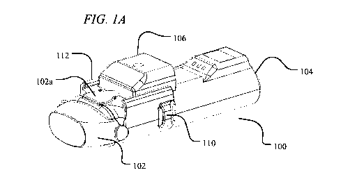
audio indications via a small speaker within the handheld base unit may
provide user
notifications. By way of example, the device may be, e.g., 2.0 -3.5 cm high, 5-
7 cm wide,
10.5-12 cm long and may weight approximately 95 grams with an empty drug
ampoule and
with batteries inserted.
[0091] As
described herein, in certain embodiments, the in-line droplet delivery
device may be turned on and activated for use by inserting the drug ampoule
into the base
unit, opening the mouthpiece cover, and/or switching an on/off switch/slide
bar. In certain
embodiments, visual and/or audio indicators may be used to indicate the status
of the device
in this regard, e.g., on, off, stand-by, preparing, etc. By way of example,
one or more LED
lights may turn green and/or flash green to indicate the device is ready for
use. In other
embodiments, visual and/or audio indicators may be used to indicate the status
of the drug
ampoule, including the number of doses taken, the number of doses remaining,
instructions
for use, etc. For example, and LED visual screen may indicate a dose counter
numerical
display with the number of remaining doses in the reservoir.
[0092] As
described in further detail herein, during use as a user inhales through the
mouthpiece of the housing of an in-line droplet delivery device of the
disclosure, a
differential pressure sensor within the housing detects inspiratory flow,
e.g., by measuring the
pressure drop across a Venturi plate at the back of the mouthpiece. When a
threshold
pressure decline (e.g., 8 slm) is attained, the microprocessor activates the
ejector mechanism,
which in turn generates an ejected stream of droplets into the airflow of the
device that the
18
CA 03087769 2020-07-06
WO 2019/136437
PCT/US2019/012691
user inhales through the mouthpiece. In certain embodiments, audio and/or
visual indicates
may be used to indicate that dosing has been initiated, e.g., one or more LEDs
may illuminate
green. The microprocessor then deactivates the ejector at a designated time
after initiation so
as to achieve a desired administration dosage, e.g., 1-1.45 seconds. In
certain embodiments,
as described in further detail herein, the device may provide visual and/or
audio indicators to
facilitate proper dosing, e.g., the device may emit a positive chime sound
after the initiation
of dosing, indicating to the user to begin holding their breath for a
designated period of time,
e.g., 10 seconds. During the breath hold period, e.g., the three green LEDs
may blink.
Additionally, there may be voice commands instructing the patient on proper
times to exhale,
inhale and hold their breath, with an audio indicator of a breath hold
countdown.
[0093]
Following dosing, the in-line droplet delivery device may turned off and
deactivated in any suitable manner, e.g., by closing the mouthpiece cover,
switching an on/off
switch/slide bar, timing out from non-use, removing the drug ampoule, etc. If
desired, audio
and/or visual indicators may prompt a user to deactivate the device, e.g., by
flashing one or
more red LED lights, providing voice commands to close the mouthpiece cover,
etc.
[0094] In
certain embodiments, the in-line droplet delivery device may include an
ejector mechanism closure system that seals the aperture plate when not in use
to protect the
integrity of the aperture plate and to minimize and prevent contamination and
evaporation of
the fluid within the reservoir. For example, in some embodiments, the device
may include a
mouthpiece cover that comprises a rubber plug that is sized and shaped to seal
the exit side
surface of the aperture plate when the cover is closed. In other embodiments,
the mouthpiece
cover may trigger a slide to seal the exit side surface of the aperture plate
when the cover is
closed. Other embodiments and configurations are also envisioned, e.g., manual
slides,
covers, and plugs, etc. In certain aspects, the microprocessor may be
configured to detect
when the ejector mechanism closure, aperture plate seal, etc. is in place, and
may thereafter
deactivate the device.
[0095]
Several features of the device allow precise dosing of specific droplet sizes.
Droplet size is set by the diameter of the holes in the mesh which are formed
with high
accuracy. By way of example, the holes in the aperture plate may range in size
from 1 um to
6 um, from 2 um to 5 um, from 3 um to 5 um, from 3 um to 4 um, etc. Ejection
rate, in
droplets per second, is generally fixed by the frequency of the aperture plate
vibration, e.g.,
108-kHz, which is actuated by the microprocessor. In certain embodiments,
there is less than
a 50-millisecond lag between the detection of the start of inhalation and full
droplet
generation.
19
CA 03087769 2020-07-06
WO 2019/136437
PCT/US2019/012691
[0096]
Other aspects of the device of the disclosure that allow for precise dosing of
specific droplet sizes include the production of droplets within the
respirable range early in
the inhalation cycle, thereby minimizing the amount of drug product being
deposited in the
mouth or upper airways at the end of an inhalation. In addition, the design of
the drug
ampoule allows the aperture plate surface to be wetted and ready for ejection
without user
intervention, thus obviating the need for shaking and priming. Further, the
design of the drug
ampoule vent configuration together with the ejector mechanism closure system
limits fluid
evaporation from the reservoir to less than 150 uL to 350 uL per month.
[0097] The
device may be constructed with materials currently used in FDA cleared
devices. Standard manufacturing methods may be employed to minimize
extractables.
[0098] Any
suitable material may be used to form the housing of the droplet delivery
device. In particular embodiment, the material should be selected such that it
does not
interact with the components of the device or the fluid to be ejected (e.g.,
drug or medicament
components). For example, polymeric materials suitable for use in
pharmaceutical
applications may be used including, e.g., gamma radiation compatible polymer
materials such
as polystyrene, polysulfone, polyurethane, phenolics, polycarbonate,
polyimides, aromatic
polyesters (PET, PETG), etc.
[0099] The
drug ampoule may be constructed of any suitable materials for the
intended pharmaceutical use. In particular, the drug contacting portions may
be made from
material compatible with the desired active agent(s), e.g., albuterol sulfate
and ipratropium
bromide. By way of example, in certain embodiments, the drug only contacts the
inner side
of the drug reservoir and the inner face of the aperture plate and
piezoelectric element. Wires
connecting the piezoelectric ejector mechanism to the batteries contained in
the base unit may
be embedded in the drug ampoule shell to avoid contact with the drug. The
piezoelectric
ejector may be attached to the drug reservoir by a flexible bushing. To the
extent the bushing
may contact the drug fluid, it may be, e.g., any suitable material known in
the art for such
purposes such as those used in piezoelectric nebulizers.
[00100] In
certain embodiments, the device mouthpiece may be removable,
replaceable and may be cleaned. Similarly, the device housing and drug ampoule
can be
cleaned by wiping with a moist cloth. In certain embodiments, the mouthpiece
may be
interfaced with (and optionally removable and/or replaceable), integrated
into, or part of the
housing. In other embodiments, the mouthpiece may be interfaced with (and
optionally
removable and/or replaceable), integrated into, or part of the drug delivery
ampoule.
CA 03087769 2020-07-06
WO 2019/136437
PCT/US2019/012691
[00101]
Again, any suitable material may be used to form the mouthpiece of the
droplet delivery device. In particular embodiment, the material should be
selected such that it
does not negatively interact with the components of the device or the fluid to
be ejected (e.g.,
drug or medicament components). For example, polymeric materials suitable for
use in
pharmaceutical applications may be used including, e.g., gamma radiation
compatible
polymer materials such as polystyrene, polysulfone, polyurethane, phenolics,
polycarbonate,
polyimides, aromatic polyesters (PET, PETG), etc. In certain embodiments, the
mouthpiece
may be removable, replaceable and sterilizable. This feature improves
sanitation for drug
delivery by providing a mechanism to minimize buildup of aerosolized
medication within the
mouthpiece and by providing for ease of replacement, disinfection and washing.
In one
embodiment, the mouthpiece tube may be formed from sterilizable and
transparent polymer
compositions such as polycarbonate, polyethylene or polypropylene, as
discussed herein.
[00102] In
certain aspects of the disclosure, an electrostatic coating may be applied to
the one or more portions of the housing, e.g., inner surfaces of the housing
along the airflow
pathway such as the mouthpiece, to aid in reducing deposition of ejected
droplets during use
due to electrostatic charge build-up. Alternatively, one or more portions of
the housing may
be formed from a charge-dissipative polymer. For instance, conductive fillers
are
commercially available and may be compounded into the more common polymers
used in
medical applications, for example, PEEK, polycarbonate, polyolefins
(polypropylene or
polyethylene), or styrenes such as polystyrene or acrylic-butadiene-styrene
(ABS)
copolymers. Alternatively, in certain embodiments, one or more portions of the
housing, e.g.,
inner surfaces of the housing along the airflow pathway such as the
mouthpiece, may be
coated with anti-microbial coatings, or may be coated with hydrophobic
coatings to aid in
reducing deposition of ejected droplets during use. Any suitable coatings
known for such
purposes may be used, e.g., polytetrafluoroethylene (Teflon).
[00103] Any
suitable differential pressure sensor with adequate sensitivity to measure
pressure changes obtained during standard inhalation cycles may be used, e.g.,
5 SLM, 10
SLM, 20 SLM, etc. For instance, pressure sensors from Sensirion, Inc., SDP31
or SDP32
(US 7,490,511 B2) are particularly well suited for these applications.
[00104] In certain aspects, the microprocessor in the device may be
programmed to
ensure exact timing and actuation of the ejector mechanism in accordance with
desired
parameters, e.g., based duration of piezoelectric activation to achieve
desired dosages, etc. In
certain embodiments, the device includes or interfaces with a memory (on the
device,
smartphone, App, computer, etc.) to record the date-time of each ejection
event, as well as the
21
CA 03087769 2020-07-06
WO 2019/136437
PCT/US2019/012691
user's inhalation flow rate during the dose inhalation to facilitate user
monitoring, as well as
drug ampoule usage monitoring. For instance, the microprocessor and memory can
monitor
doses administered and doses remaining in a particular drug ampoule. In
certain
embodiments, the drug ampoule may comprise components that include
identifiable
information, and the base unit may comprise components that may "read" the
identifiable
information to sense when a drug ampoule has been inserted into the base unit,
e.g., based on
a unique electrical resistance of each individual ampoule, an RFID chip, or
other readable
microchip (e.g., cryptoauthentication microchip). Dose counting and lockouts
may also be
preprogramed into the microprocessor.
[00105] In certain embodiments of the present disclosure, the signal
generated by the
pressure sensors provides a trigger for activation and actuation of the
ejector mechanism to
thereby generate droplets and delivery droplets at or during a peak period of
a patient's
inhalation (inspiratory) cycle and assures optimum deposition of the plume of
droplets and
delivery of the medication into the pulmonary airways of the user.
[00106] In accordance with certain aspects of the disclosure, the in-line
droplet
delivery device provides a reliable monitoring system that can date and time
stamp actual
deliver of medication, e.g., to benefit patients through self-monitoring or
through
involvement of care givers and family members.
[00107] As
described in further detail herein, the in-line droplet delivery device of the
disclosure may detect inspiratory airflow and record/store inspiratory airflow
in a memory
(on the device, smartphone, App, computer, etc.). A preset threshold (e.g., 8-
10 slm) triggers
delivery of medication over a defined period of time, e.g., 1-1.5 seconds.
Inspiratory flow is
sampled frequently until flow stops. The number of times that delivery is
triggered is
incorporated and displayed in the dose counter LED on the device. Blue tooth
capabilities
permit the wireless transmission of the data.
[00108]
Bluetooth communication in the device will communicate date, time and
number of actuations per session to the user's smartphone. Software programing
can provide
charts, graphics, medication reminders and warnings to patients and whoever is
granted
permission to the data. The software application will be able to incorporate
multiple
medications that use the device of the disclosure.
[00109] The
device of the disclosure can also provide directed instruction to users,
including audio and visual indicators to facilitate proper use of the device
and proper dosing.
For instance, certain patients that may need drug to be delivered to an
inflamed and narrowed
lower respiratory region are typically asked to inhale drug particles slowly
and steadily
22
CA 03087769 2020-07-06
WO 2019/136437
PCT/US2019/012691
followed by about ten seconds of holding their breath to allow sedimentation
to occur. In a
medical office these patients can be coached and encouraged to hold their
breath after
inhalation. However, outside of a medical care setting, improper use of an
inhaler device
often results.
[00110] The device of the present disclosure is configured to dispense
droplets during
the correct part of the inhalation cycle, and can including instruction and/or
coaching features
to assist patients with proper device use, e.g., by instructing the holding of
breath for the
correct amount of time after inhalation. The device of the disclosure allows
this dual
functionality because it may both monitor air flow during the inhalation, and
has internal
sensors/controls which may detect the end of inhalation (based upon measured
flow rate) and
can cue the patient to hold their breath for a fixed duration after the
inhalation ceases.
[00111] In
one exemplary embodiment, a patient may be coached to hold their breath
with an LED that is turned on at the end of inhalation and turned off after a
defined period of
time (i.e., desired time period of breath hold), e.g., 10 seconds.
Alternatively, the LED may
blink after inhalation, and continue blinking until the breath holding period
has ended. In this
case, the processing in the device detects the end of inhalation, turns on the
LED (or causes
blinking of the LED, etc.), waits the defined period of time, and then turns
off the LED.
Similarly, the device can emit audio indications, e.g., one or more bursts of
sound (e.g., a 50
millisecond pulse of 1000 Hz), verbal instructions to hold breath, verbal
countdown, music,
tune, melody, etc., at the end of inhalation to cue a patient to hold their
breath for the during
of the sound signals. If desired, the device may also vibrate during or upon
conclusion of the
breath holding period.
[00112] In
certain embodiments, the device provides a combination of audio and visual
methods (or sound, light and vibration) described above to communicate to the
user when the
breath holding period has begun and when it has ended. Or during the breath
holding to show
progress (e.g., a visual or audio countdown).
[00113] In
other aspects, the device of the disclosure may provide coaching to inhale
longer, more deeply, etc. The average peak inspiratory flow during inhalation
(or dosing) can
be utilized to provide coaching. For example, a patient may hear a breath
deeper command
until they reach 90% of their average peak inspiratory flow as measured during
inspiration
(dosing) as stored on the device, phone or in the cloud.
[00114] In
addition, an image capture device, including cameras, scanners, or other
sensors without limitation, e.g. charge coupled device (CCD), may be provided
to detect and
measure the ejected aerosol plume. These detectors, LED, delta P transducer,
CCD device,
23
CA 03087769 2020-07-06
WO 2019/136437
PCT/US2019/012691
all provide controlling signals to a microprocessor or controller in the
device used for
monitoring, sensing, measuring and controlling the ejection of a plume of
droplets and
reporting patient compliance, treatment times, dosage, and patient usage
history, etc., via
Bluetooth, for example.
[00115] Reference will now be made to the figures, with like components
illustrates
with like references numbers.
[00116]
FIGS. 1A and 1B illustrate an exemplary in-line droplet delivery device of the
disclosure, with FIG. 1A showing the in-line droplet delivery device 100
having a
mouthpiece cover 102 in the closed position, and FIG. 1B having a mouthpiece
cover 102 in
the open position. As shown, the droplet delivery device is configured in an
in-line
orientation in that the housing, its internal components, and various device
components (e.g.,
the mouthpiece, air inlet flow element, etc.) are orientated in a
substantially in-line or parallel
configuration (e.g., along the airflow path) so as to form a small, hand-held
device.
[00117] In
the embodiment shown in FIGS. 1A and 1B, the in-line droplet delivery
device 100 includes a base unit 104 and a drug delivery ampoule 106. As
illustrated in this
embodiment, and discussed in further detail herein, the drug delivery ampoule
106 slides into
the front of the base unit 104 via slides 112. In certain embodiments,
mouthpiece cover 102
may include a push element 102a that facilitates insertion of drug delivery
ampoule 106.
Also illustrated are one or more airflow entrances or openings 110. By way of
example, there
may be airflow entrances on the opposite side of the device, multiple airflow
entrances on the
same side of the device, or a combination thereof (not shown). The in-line
droplet delivery
device 100 also includes mouthpiece 108 at the airflow exit side of the
device.
[00118]
With reference to FIG. 2, an exploded view of the exemplary in-line droplet
delivery device of FIGS. 1A and 1B is shown, including internal components of
the housing
including a power/activation button 201; an electronics circuit board 202; a
drug delivery
ampoule 106 that comprises an ejector mechanism and reservoir (not shown); and
a power
source 203 (e.g., three AAA batteries, which may optionally be rechargeable)
along with
associated contacts 203a. In certain embodiments, the reservoir may be single-
unit dose or
multi-unit dose that may be replaceable, disposable or reusable. Also shown,
one or more
pressure sensors 204 and optional spray sensors 205. In certain embodiments,
the device may
also include various electrical contacts 210 and 211 to facilitate activation
of the device upon
insertion of drug delivery ampoule 106 into the base unit. Likewise, in
certain embodiments,
the device may include slides 212, posts 213, springs 214, and ampoule lock
215 to facilitate
insertion of drug delivery ampoule 106 into the base unit.
24
CA 03087769 2020-07-06
WO 2019/136437
PCT/US2019/012691
[00119] The
components may be packaged in a housing, and generally oriented in an
in-line configuration. The housing may be disposable or reusable, single-dose
or multi-dose.
Although various configurations to form the housing are within the scope of
the disclosure, as
illustrated in FIG. 2, the housing may comprise a top cover 206, a bottom
cover 207, and an
inner housing 208. The housing may also include a power source housing or
cover 209.
[00120] In
certain embodiments, the device may include audio and/or visual
indications, e.g., to provide instructions and communications to a user. In
such embodiments,
the device may include a speaker or audio chip (not shown), one or more LED
lights 216, and
LCD display 217 (interfaced with an LCD control board 218 and lens cover 219).
The
housing may be handheld and may be adapted for communication with other
devices via a
Bluetooth communication module or similar wireless communication module, e.g.,
for
communication with a subject's smart phone, tablet or smart device (not
shown).
[00121] In
certain embodiments, an air inlet flow element (not shown, see, e.g., FIGS.
5A-5C and FIGS. 11A-18D) may be positioned in the airflow at the airflow
entrance of the
housing and configured to facilitate non-turbulent (i.e., laminar and/or
transitional) airflow
across the exit side of aperture plate and to provide sufficient airflow to
ensure that the
ejected stream of droplets flows through the droplet delivery device during
use. In some
embodiments, the air inlet flow element may be positioned within the
mouthpiece. Aspects
of the present embodiment further allows customizing the internal pressure
resistance of the
particle delivery device by allowing the placement of laminar flow elements
having openings
of different sizes and varying configurations to selectively increase or
decrease internal
pressure resistance, as will be explained in further detail herein.
[00122] By
way of non-limiting example, an exemplary method of insertion of an
ampoule through to use and powering off of the device may be performed as
follows:
1. When a new
ampoule is initially inserted and pushed onto the device slide
guide the device door is open and the ampoule slides and clicks into ampoule
position
1. At this setting, an aperture plate seal or cover on the ampoule is open and
electrical
contacts on the device and ampoule make contact. The system is powered ON and
ready for breath actuation. When the device door is opened, an audible beep
may be
emitted and LED indicator(s) may turn green or flash to notify the user that
the
system is ON and ready for dosing by inhaling through the mouthpiece.
2. As a patient inhales, a pre-set pressure value is reached and detected
by the
pressure sensor located within the housing (e.g., delta P sensor) and a second
audible
indicator or LED indicator may now indicate that a dose is triggered. After
the dose is
CA 03087769 2020-07-06
WO 2019/136437
PCT/US2019/012691
triggered and delivered, another audible and/or LED indicator may trigger
until a
spray cycle time of, e.g., 1-5 seconds (or other designated dosing time) ends.
Further,
if desired, when a dose is delivered, the dose counter displayed on the LCD
will
indicate that a dose was delivered by a decrease in number of doses displayed
on the
LCD.
3. If no additional doses are required and a time of, e.g., 15 seconds
elapse, an
audible and/or LED indicator may trigger to alert the user that the device is
about to
power-off, after which time the device may enter into a low power, sleep mode.
4. If no additional doses are required, the device door is closed to push
the
ampoule to the non-use position, the aperture plate seal or cover is closed
and the
device is in placed sleep mode. Further, as the slide mechanism releases
pressure
from the ON/OFF switch, and the system is now OFF.
S.
When a patient is ready to apply additional doses, the device door is opened
and the ampoule slides towards the mouthpiece as it is pushed by a spring-
loaded
mechanism from the non-use position to the use position, to thereby open the
aperture
plate seal or cover.
[00123]
More particularly, a specific exemplary embodiment of a mode of operation of
insertion of a drug ampoule and operation of a device is illustrated in FIGS.
3A-1 to FIG.
3C-3. Referring to FIG. 3A-1 and 3A-2, when a drug ampoule (1), is initially
inserted and
pushed onto the device slide guide (la), the device door (2) is open, the
ampoule slides and
clicks into ampoule position 1. An oval button (ampoule lock) (lb) clicks down
and snaps
back to lock the ampoule in place. At this setting, the seal on the aperture
plate is open, the
four electrical contacts on the device and ampoule make contact, and the
system is powered
ON, ready for breath actuation. The front two contacts (3) complete the
circuit to actuate the
piezoelectric element, while the rear two contacts (4) are used to provide
specific information
on the ampoule, such as ampoule ID, drug type, dosage, etc.
[00124]
Referring to FIG. 3B-1 and 3B-2, ampoule position 1(A) is shown, in which
the oval button (lb) locks the ampoule into place and the four electrical
contacts, front (3)
and rear (4) connect to complete the electric circuit. When the ampoule is in
position 1, the
electronic component that activates the ON/OFF button (lc) is pushed by the
spring-loaded,
slide mechanism (5). FIG. 3B-1 provides a bottom view of the spring-loaded
slide
mechanism (5) and the ON/OFF button (lc), in the ON mode. FIG. 3B-2 provides
an
exploded view (5a) of side brackets on the spring-loaded slide (5) and their
position (5a- dash
arrows) through slots (5b) on the device which make contact on the ampule (Sc)
to push the
26
CA 03087769 2020-07-06
WO 2019/136437
PCT/US2019/012691
ampule forward when the device door is opened and activate the ON/OFF switch
(1c) as it
makes contact with the ON/OFF button (1d). The device ON/OFF button (1c) is
activated by
the slide (5) when the mouthpiece cover (2) is closed and pushes the ampule
back to position
2, where the aperture plate seal is in the closed position and power is turned
OFF to the
device as pressure on the ON/OFF switch is released.
[00125]
Referring to FIG. 3C-1, 3C-2, and 3C-3, cross-sections of the device with the
ampoule inserted are illustrated to better illustrate the ampoule slide
mechanism and
positioning of the ON/OFF switch. FIG. 3C-1 shows ampoule position 1, with the
mouthpiece cover in the open position and the ON/OFF switch in the ON
position. FIG. 3C-
2 shows ampoule position 2, with the mouthpiece cover in the closed position
and the
ON/OFF switch in the OFF position. FIG. 3C-3 shows ampoule position 2, with
the
mouthpiece cover in the open position and the ON/OFF switch in the OFF
position.
[00126]
However, it is noted that the devices and methods of the disclosure are not so
limited, and various modifications and expansions of the method of operation
is envisioned as
within the scope of the disclosure.
[00127] In
another embodiment, FIGS. 4A and 4B illustrate an alternative in-line
droplet delivery device of the disclosure, with FIG. 4A showing the in-line
droplet delivery
device 400 with a base unit 404 having a mouthpiece cover 402 in the closed
position, and
FIG. 4B with a base unit 404 having a mouthpiece cover 402 in the open
position. As
shown, the droplet delivery device is configured in an in-line orientation in
that the housing,
its internal components, and various device components (e.g., the mouthpiece,
air inlet flow
element, etc.) are orientated in a substantially in-line or parallel
configuration (e.g., along the
airflow path) so as to form a small, hand-held device.
[00128] In
the embodiment shown in FIGS. 4A and 4B, the in-line droplet delivery
device 400 includes a base unit 404 and a drug delivery ampoule 406. As
illustrated in this
embodiment, and discussed in further detail herein, the drug delivery ampoule
406 slides into
the front of the base unit 404. In certain embodiments, mouthpiece cover 402
may include
aperture plate plug 412. Also illustrated are one or more airflow entrances or
openings 410 in
mouthpiece 408. By way of example, there may be airflow entrances on the
opposite side of
the device, multiple airflow entrances on the same side of the device, or a
combination
thereof (not shown). The in-line droplet delivery device 400 also includes
mouthpiece 408 at
the airflow exit side of the device.
[00129]
With reference to FIG. 5, an exploded view of the exemplary in-line droplet
delivery device of FIGS. 4A and 4B is shown, including internal components of
the housing
27
CA 03087769 2020-07-06
WO 2019/136437
PCT/US2019/012691
including an electronics circuit board 502; a drug delivery ampoule 406 that
comprises top
cover 430 having optional vents 431 and vapor barriers 432, an ejector
mechanism 434, a
drug reservoir 435, electrical contacts 436, and one or more sensor ports 437;
and a power
source 503 (e.g., three AAA batteries, which may optionally be rechargeable).
In certain
embodiments, the device may also include various electrical contacts 442 and
sensor ports
444 to facilitate activation of the device upon insertion of drug delivery
ampoule 406 into the
base unit 404. Likewise, in certain embodiments, the device may include
resistors or chips
504 to facilitate insertion and detection of drug delivery ampoule 406 into
the base unit 404.
[00130] In
certain embodiments, the reservoir may be single-unit dose or multi-unit
dose that may be replaceable, disposable or reusable. As illustrated in FIG.
5, in certain
embodiments, the drug delivery ampoule may also comprise or be interfaced with
a
mouthpiece 408 and a mouthpiece cover 402. As shown, ejector mechanism 434 may
be
positioned in line with mouthpiece 408 and drug reservoir 435 such that the
exit side of the
aperture plate is perpendicular to the direction of airflow and the stream of
droplets is ejected
.. in parallel to the direction of airflow. The mouthpiece cover 402 may
further include an
aperture plate plug 412.
[00131] The
components may be packaged in a housing, and generally oriented in an
in-line configuration. The housing may be disposable or reusable, single-dose
or multi-dose.
Although various configurations to form the housing are within the scope of
the disclosure, as
illustrated in FIG. 5, the housing may comprise a top cover 506, a bottom
cover 507, and an
inner housing 508. The device may also include one or more ampoule release
buttons 550,
e.g., positioned on the side of the housing to facilitate release of the drug
delivery ampoule
406 once inserted into the base unit 404.
[00132] In
certain embodiments, the device may include audio and/or visual
indications, e.g., to provide instructions and communications to a user. In
such embodiments,
the device may include a speaker or audio chip 520, one or more LED lights
516, and LCD
display 517 (interfaced with an LCD control board 518 and lens cover 519). The
housing
may be handheld and may be adapted for communication with other devices via a
Bluetooth
communication module or similar wireless communication module, e.g., for
communication
with a subject's smart phone, tablet or smart device (not shown).
[00133]
With reference to FIG. 6, a cross-section of an in-line device of FIGS. 4A and
4B is shown to illustrate an exemplary configuration of the interior of the
drug reservoir 435
and its relation to ejector mechanism 434. As shown, drug reservoir 435 may be
sized and
shaped such that the volume of fluid held within the reservoir is funneled and
directed to the
28
CA 03087769 2020-07-06
WO 2019/136437
PCT/US2019/012691
ejection surface of the aperture plate during use. More particularly, as
shown, the bottom
surface of the drug reservoir may be sloped towards the ejector mechanism so
as to facilitate
flow of the fluid within the drug reservoir during use. Without intending to
be limited by
theory, such configurations may be particularly suited for device orientations
wherein the
ejector mechanism is oriented perpendicularly to the direction of airflow.
However, it is
noted that the disclosure is not so limited, and various shapes, sizes and
configurations of
ampoule are envisioned as within the scope of the disclosure.
[00134]
FIG. 7 illustrates the base unit 404 of the embodiment of FIGS. 4A and 4B
without the drug delivery ampoule inserted. Without the drug delivery ampoule
inserted,
.. tracks 440 for directing the ampoule into place, electrical contacts 442,
and sensor port 444
are shown. Also shown is release button 450.
[00135]
FIGS. 8A and 8B illustrate a drug delivery ampoule 406 with mouthpiece
cover 402 attached and in a closed position in front view (FIG. 8A) and back
view (FIG.
8B). FIG. 8B illustrates electrical contacts 436 and sensor port 437 of the
ampoule, as well
as protruding slides 452 to facilitate placement of the ampoule into tracks
440 during
insertion. By way of example, when drug delivery ampoule 406 is inserted into
base unit
404, protruding slides 452 mate with tracks 440, sensor port 437 mates with
sensor port 444,
and electrical contacts 436 mates with electrical contacts 442. The drug
delivery ampoule is
pushed into the base unit and locked into place with the protruding slides and
tracks engaging
.. one another. During use, a pressure sensor located on the control board
senses pressure
changes within the device via the pressure sensing ports (e.g., within the
mouthpiece). To
facilitate detection of pressure changes, the base unit includes a second
pressure sensing port
and outside channel (not shown) to facilitate sensing of reference or ambient
pressure.
[00136] As
discussed herein, the drug reservoir and/or drug delivery ampoule may
include various vents and/or vapor barriers to facilitate venting, etc. With
reference to FIGS.
9A-9C, an exemplary reservoir or ampoule is shown which is configured so as to
be
insensitive to pressure differentials that may occur when the user travels
from sea level to
sub-sea levels and at high altitudes, e.g., while traveling in an airplane
where pressure
differentials may be as great as 4 psi. As shown, FIG. 9A shows a perspective
view of an
exemplary ampoule 900. FIGS 9B and 9C show exploded view of ampoule 900 from
perspective top and bottom views. With reference to FIGS. 9B and 9C, the
ampoule 900
generally includes a top cover 901 and a bottom cover 902. The ampoule 900 may
be
configured to include one or more superhydrophobic filter(s) 904 covering one
or more vents
906, and the fluid reservoir housing may include a spiral channel (or
similarly shaped) vapor
29
CA 03087769 2020-07-06
WO 2019/136437
PCT/US2019/012691
barrier 905, which provides for free exchange of air into and out of the fluid
reservoir, while
blocking moisture or fluids from passing into the reservoir, thereby reducing
or preventing
fluid leakage or deposition on aperture plate surfaces. If desired, one or
more 0-rings 903, or
similar sealing mechanism, may be used to form a seal between the top cover
901 and the
bottom cover 902 in connection with the vapor barrier 905. Without intending
to be limited,
the superhydrophobic filter and vent may generally allow for the venting of
air and
equilibration of air pressure within the fluid reservoir, while maintaining a
sterile
environment within the fluid reservoir. The spiral channel vapor barrier will
generally
prevent the transfer of moisture to and from the fluid reservoir (e.g.,
through the vent
opening).
[00137] In
another embodiment, shown in FIG. 9D, a cross-section of an exemplary
small volume drug ampoule 910 is illustrated. As shown, the small volume drug
ampoule
910 includes a membrane 920, which separates the reservoir into two volumes, a
first
background pressure fluid volume 925, and a second drug fluid volume 930. The
small
volume ampoule may also include an air exchange vent (e.g., a superhydrophobic
filter) 935,
and an option fill port 940. Any suitable size and shape configuration of
reservoir may be
used. By way of non-limiting example, for 20 uL dose on a 5 mm ejector, a
small volume
ampoule may be sized and shaped so as to be 5 mm diameter by 1 mm high well.
[00138] In
accordance with aspects, the in-line droplet delivery devices of the
disclosure may include an air inlet flow element (see, e.g., FIGS. 10A-10C and
12A-19D)
which may be positioned in the airflow at the airflow entrance of the device
and configured to
facilitate non-turbulent (i.e., laminar and/or transitional) airflow across
the exit side of
aperture plate and to provide sufficient airflow to ensure that the ejected
stream of droplets
flows through the droplet delivery device during use. In some embodiments, the
air inlet flow
element may be positioned within the mouthpiece. Aspects of the present
embodiment
further allows customizing the internal pressure resistance of the particle
delivery device by
allowing the placement of laminar flow elements having openings of different
sizes and
varying configurations to selectively increase or decrease internal pressure
resistance, as will
be explained in further detail herein.
[00139] In accordance with certain embodiments of the in-line droplet
delivery device
of the disclosure, the device may include an air inlet flow element may be
positioned in the
airflow at the airflow entrance of the device and configured to facilitate non-
turbulent (i.e.,
laminar and/or transitional) airflow across the exit side of aperture plate
and to provide
sufficient airflow to ensure that the ejected stream of droplets flows through
the droplet
CA 03087769 2020-07-06
WO 2019/136437
PCT/US2019/012691
delivery device during use. In some embodiments, the air inlet flow element
may be
positioned within the mouthpiece. In addition, the air inlet flow element
allows for
customization of internal device pressure resistance by designing openings of
different sizes
and varying configurations to selectively increase or decrease internal
pressure resistance.
[00140] As will be described in further detail herein, the air inlet flow
element may be
positioned behind the exit side of the aperture plate along the direction of
airflow, or in-line
or in front of the exit side of the aperture plate along the direction of
airflow. In certain
embodiments, the air inlet flow element comprises one or more openings formed
there
through and configured to increase or decrease internal pressure resistance
within the droplet
delivery device during use. For instance, the air inlet flow element comprises
an array of one
or openings. In the embodiments, the air inlet flow element comprises one or
more baffles,
e.g., wherein the one or more baffles comprise one or more airflow openings.
[00141] In
certain embodiments, the air inlet flow element is designed and configured
in order to provide an optimum airway resistance for achieving peak
inspirational flows that
are required for deep inhalation which promotes delivery of ejected droplets
deep into the
pulmonary airways. Air inlet flow elements also function to promote non-
turbulent flow
across the aerosol plume exit port, which also serves to stabilize airflow
repeatability,
stability and insures an optimal precision in the delivered dose.
[00142]
Without intending to be limited by theory, in accordance with aspects of the
disclosure, the size, number, shape and orientation of flow restrictions
(e.g., openings, holes,
flow blocks, etc.) in the air inlet flow element of the disclosure may be
configured to provide
a desired pressure drop within the in-line droplet delivery device. In certain
embodiments, it
may be generally desirable to provide a pressure drop that is not so large as
to strongly affect
a user's breathing or perception of breathing.
[00143] In certain implementations, the use of air inlet flow elements
having
differently configured, sized, and shaped flow restrictions (e.g., openings,
holes, flow blocks,
etc.), or the use of adjustable apertures may be required in order to
accommodate the
differences among the lungs and associated inspiratory flow rates of young and
old, small and
large, and various pulmonary disease states. For example, if the aperture is
adjustable by the
patient (perhaps by having a slotted ring that can be rotated), then a method
may be provided
to read the aperture hole setting and lock that position to avoid inadvertent
changes of the
aperture hole size, hence the flow measurement. Although pressure sensing is
an accurate
method for flow measurement, other embodiments may use, e.g., hot wires or
thermistor
types of flow rate measurement methods which lose heat at a rate proportional
to flow rate,
31
CA 03087769 2020-07-06
WO 2019/136437
PCT/US2019/012691
moving blades (turbine flow meter technology) or by using a spring-loaded
plate, without
limitation of example.
[00144] For
instance, FIGS. 10A-10C illustrate certain exemplary air inlet flow
elements of the disclosure. FIGS. 10A-10C also illustrate the position of
pressure sensors,
the mouthpiece, and air channels for reference pressure sensing. However, the
disclosure is
not so limited, and other configurations including those described herein are
contemplated as
within the scope of the disclosure. While not being so limited, the air inlet
flow elements of
FIGS. 10A-10C are particularly suitable for use with the in-line droplet
delivery devices of
FIGS. 1A-1B.
[00145] More particularly, FIG. 10A illustrates a cross-section of a
partial in-line
droplet delivery device 1000 of the disclosure including a mouthpiece cover
1001, a
mouthpiece 1002, a drug delivery ampoule 1003 comprising a drug reservoir 1004
and an
ejector mechanism 1005. As illustrated, the droplet delivery device includes
an air inlet flow
element 1006 having an array of holes 1006a at the air entrance of the
mouthpiece 1002.
Also shown is a pressure sensor port 1007, which may be used to sense a change
in pressure
within the mouthpiece. With reference to FIG. 10B, a front view of the device
1000 is
illustrated, wherein a second pressure sensor port 1008 is shown to provide
for sensing of a
reference or ambient pressure.
[00146]
FIG. 10C illustrates a partial exploded view including mouthpiece 1002 and
inner housing 1011. As shown, mouthpiece 1002 includes air intake flow element
1006 with
an array of holes 1006a, and pressure sensor port 1007. Further, mouthpiece
1002 may
include an ejection port 1114 positioned, e.g., on the top surface of the
mouthpiece so as to
align with the ejector mechanism to allow for ejection of the stream of
droplets into the
airflow of the device during use. Other sensor ports 1115 may be positioned as
desired along
the mouthpiece to allow for desired sensor function, e.g., spray detection.
The mouthpiece
may also include positioning baffle 1116 that interfaces with the base unit
upon insertion.
Inner housing 1011 includes pressure sensor board 1009 and outside channel
1010 for
facilitating sensing of reference or ambient pressure. The inner housing
further includes a
first pressure sensing port 1112 to facilitate sensing of pressure changes
within the device
(e.g., within the mouthpiece or housing), and a second pressure sensing port
1113 to facilitate
sensing of reference or ambient pressure.
[00147] In
this regard, FIG. 11A illustrates differential pressure as a function of flow
rates through exemplary air inlet flow elements similar to that of FIGS. 10A-
10C as a
function of number of holes (29 holes, 23 holes, 17 holes). Referring to FIG.
11B, the flow
32
CA 03087769 2020-07-06
WO 2019/136437
PCT/US2019/012691
rate verses differential pressure as a function of hole size is shown to have
a liner
relationship, when flow rate is plotted as a function of the square root of
differential pressure.
The number of holes is held constant at 17 holes. These data provide a manner
to select a
design for an air inlet flow element to provide a desired pressure resistance,
as well as
provide a model for the relationship between flow rate and differential
pressure, as measured
in an exemplary droplet delivery device.
Inspiratory Flow Rate (SLM) = C(SqRt) (Pressure(Pa))
Hole Size (mm) Pressure at Equation
Element # (17 holes) 10 slm (Pa) Flow at 1000 Pa Constant (C)
0 1.9 6 149.56 4.73
1 2.4 2.1 169.48 5.36
2 2.7 1.7 203.16 6.43
3 3 1.3 274.46 8.68
[00148] A
particular non-limiting exemplary air inlet flow element may 29 holes, each
1.9 mm in diameter. However, the disclosure is not so limited. For example,
the air inlet flow
element may have hole diameters ranging from, e.g., 0.1 mm in diameter to
diameters equal
to the cross sectional diameter of the air inlet tube (e.g., 0.5 mm, 1 mm, 1.5
mm, 2 mm, 2.5
mm, 3 mm, 3.5 mm, 4 mm, 4.5 mm, 5 mm, 5.5 mm, 6 mm, 6.5 mm, etc.), and number
of
holes may range from 1 to the number of holes, for example, to achieve the
desire air flow
.. resistance, e.g., 2, 3, 4, 5, 6, 7, 8, 9, 10, 15, 20, 25, 29, 30, 60, 90,
100, 150, etc.
[00149]
FIGS. 12A-19D illustrate alternative embodiments of air inlet flow elements
of the disclosure. FIGS. 12A-19D also illustrate exemplary positioning of air
inlet flow
elements within the airflow of a device, within the mouthpiece, as well as the
interfacing of a
mouthpiece including an air inlet flow element to an drug delivery ampoule.
[00150] FIG. 12A shows an exemplary drug delivery ampoule with a mouthpiece
interfaced at the airflow exit side of the device. The mouthpiece includes two
airflow
entrances on the sides, but no internal air inlet flow elements to provide
resistance to airflow.
FIG. 12B shows a front cross-section and 12C shows a side cross-section, with
FIG. 12D
showing the same views with exemplary dimensions. FIGS. 13A and 14A show
similarly
configured mouthpieces with two airflow entrances on the sides, but no
internal air inlet flow
elements to provide resistance to airflow. Again, FIGS. 13B and 14B show a
front cross-
section and 13C and 14C show a side cross-section, with FIGS. 13D and 14D
showing the
same views with exemplary dimensions to illustrate the differences in
configurations between
the embodiments. For instance, the embodiment of FIG. 12 has openings that are
6.6 mm
33
CA 03087769 2020-07-06
WO 2019/136437
PCT/US2019/012691
long and 2 mm high, the embodiment of FIG. 13 has openings that are 7.9 mm
long and 2.5
mm high, and the embodiment of FIG. 14 has openings that are 8.1 mm long and 3
mm high.
Of course, the disclosure is not limited to these specific dimensions, and
varied dimensions
and numbers of air inflow openings are envisions as within the scope of the
disclosure.
[00151] FIG. 15A shows an exemplary drug delivery ampoule with a mouthpiece
interfaced at the airflow exit side of the device. The mouthpiece includes two
airflow
entrances on the exterior sides of the mouthpiece, and two interior baffles
with additional
airflow entrances to provide resistance and modeling of airflow. FIG. 15B
shows a front
cross-section and 15C shows a side cross-section, with FIG. 15D showing the
same views
with exemplary dimensions. FIG. 16A shows a similarly configured mouthpiece
that
includes two airflow entrances on the exterior sides of the mouthpiece, and
two interior
baffles with additional airflow entrances to provide resistance and modeling
of airflow.
However, the interior baffles of FIG. 16A are larger (10 mm in height) than
that of FIG. 15A
(5 mm in height). FIG. 16B shows a front cross-section and 16C shows a side
cross-section,
with FIG. 16D showing the same views with exemplary dimensions.
[00152]
FIG. 17A shows an exemplary drug delivery ampoule with a mouthpiece
interfaced at the airflow exit side of the device. The mouthpiece includes two
airflow
entrances on the exterior sides of the mouthpiece, and a substantially
concentric baffle (two
arcs that form a circle with the top and bottom of the mouthpiece) with two
additional airflow
entrances to provide resistance and modeling of airflow. FIG. 17B shows a
front cross-
section and 17C shows a side cross-section, with FIG. 17D showing the same
views with
exemplary dimensions. FIG. 18A shows a similarly configured mouthpiece with a
substantially concentric interior baffle, but the interior baffle includes
four airflow entrances
to provide resistance and modeling of airflow. FIG. 18B shows a front cross-
section and
18C shows a side cross-section, with FIG. 18D showing the same views with
exemplary
dimensions.
[00153]
FIG. 19A shows an exemplary drug delivery ampoule with a mouthpiece
interfaced at the airflow exit side of the device. The mouthpiece includes two
airflow
entrances on the exterior sides of the mouthpiece, and a substantially
concentric baffle with
two additional airflow entrances to provide resistance and modeling of
airflow. In addition,
the interior area of the mouthpiece between the concentric baffle and the wall
of the
mouthpiece includes an array element positioned above the airflow entrances to
provide
additional resistance and modeling to airflow. The array element is positioned
in a parallel
arrangement with the direction of airflow. Again, FIG. 19B shows a front cross-
section and
34
CA 03087769 2020-07-06
WO 2019/136437
PCT/US2019/012691
19C shows a side cross-section, with FIG. 19D showing the same views with
exemplary
dimensions.
[00154] In
accordance with the disclosure, it has been found that the presence of inner
air inlet flow elements generally improve spray efficiency for exemplary fluid
solutions
(deionized water and albuterol solution. For instance, as shown in FIG. 20, at
30 SLM ,
inner air inlet flow elements increase spray efficiency from 47% to 66%, and
orienting
interior airflow entrances away from ejection streams improves spray
efficiency to 80% or
more. The mouthpiece and drug reservoir are a single unit and can be weighted
before
ejection (W1), after ejection (W2) and after drying (W3) the mouthpiece to
measure the
percentage of ejected drug that leaves the mouthpiece for delivery to a user.
Spray efficiency
= (W1-W2)/(W1-W3)
[00155] In
certain aspects of the disclosure, the in-line device may be configured to
protect the surface of the aperture plate, to minimize evaporation losses, and
to minimize
contamination while the device is closed and not in use. For instance, as
described herein,
when the reservoir/ampoule is in the closed position, the surface of the
aperture plate of the
ejector mechanism may be closed/sealed against the housing or the mouthpiece
cover.
However, in certain embodiments, when the reservoir/ampoule includes an 0-ring
or gasket
to facilitate the seal of the surface of the aperture plate of the ejector
mechanism, the sliding
of the reservoir/ampoule between the open and closed position may, in certain
aspects, create
friction which needs to be overcome by a compression spring during opening and
closing.
[00156] In
one embodiment, friction between the ampoule 0-ring and the device
housing may be reduced by applying a compressive force between the ampoule and
the
device housing in the last few millimeters as the ampoule is closed. Thus,
higher friction is
limited to the first few millimeters during opening, when the compression
spring is providing
the highest force; and during the last few millimeters of closing when the
ampoule door is
almost closed and force on the door is easiest for the user to apply. Force
applied as the door
is almost closed also creates minimal reaction forces at the door's hinge,
improving
robustness of the device. Applying pressure to the 0-ring over a shorter
distance also reduces
wear on the 0-ring (or gasket).
[00157] Without being limited, in certain embodiments, applying a
compressive
sealing force during the last few millimeters of ampoule motion to the closed
position can be
accomplished by utilizing a ramp on either the ampoule or device side of the
ampoule track
which engages a budge on the opposite face (device for ampoule or ampoule for
device) as
the ampoule approaches the closed position. This can also be a pair of ramps
which engage as
CA 03087769 2020-07-06
WO 2019/136437
PCT/US2019/012691
the ampoule approaches the closed position. In certain aspects, the point(s)
of contact
between the ampoule and device should be in alignment with the center of
pressure of the 0-
ring to create a uniform sealing pressure. Note that to achieve enough
compression for good
sealing, the total vertical motion created by the ramp only needs to be in the
range of 0.1 mm.
[00158] Alternatively to a sealing force generated by a fixed movement of
the ampoule
towards the device, a flexible compressive element can apply a downward force
the rises as
the ampoule approaches the closed position. By way of non-limiting example,
this could be
the ramp intersecting a flexible, rubber-like, material or a metallic or
plastic spring, including
a cantilever (leaf) spring that the ramp encounters as it arrives at the
closed position of the
ampule.
[00159] The
compressive force applied to the 0-ring does not have to be large, but
sufficient for the compliant 0-ring to seal against the surface roughness of
the device surface.
In certain embodiments, a more compliant material will require less
compressive force to
seal. Similarly, the 0-ring can be made from a slippery material such as
teflon-coated or
teflon-encapsulated material to reduce the sliding friction of the ampule.
Similarly, sealing
may be done by a lip seal at the face.
[00160]
FIGS. 21A-21C illustrate exemplary embodiments showing a ramp structure
on the ampoule lip that presses the ampoule down and compresses the 0-ring
while in the
"closed" position. Note, as illustrated the size of the ramp is greatly
exaggerated. In one
embodiment, the ramp may be about 0.1 to 0.2 mm high. FIG. 21A shows an end
view
showing ampule with lips that are engaged in track that is part of body of
device. FIG. 21B
shows how an ampoule moves from closed to open position. Mouthpiece and user
to the
right. FIG. 21C illustrates a side view of an ampoule in track with a ramp on
a lip to force a
aperture plate seal, showing a closed and open position.
[00161] In other embodiments, the surface of the aperture plate may be
protected by
the mouthpiece cover. For instance, as shown in FIG. 21D, mouthpiece cover
2100 may
include aperture plate plug 2102 that is specifically sized and shaped so as
to form a mating
seal against the surface of the aperture plate 2104 when the cover is closed.
In certain
embodiments, the aperture plate plug 2102 may have a stepped shape such that
the plug
forms a seal against the surface of the housing around the aperture plate
without putting
direct pressure on the surface of the aperture plate.
[00162] In
certain embodiments, as illustrated herein, the reservoir/cartridge module
may include components that may carry information read by the housing
electronics
including key parameters such as ejector mechanism functionality, drug
identification, and
36
CA 03087769 2020-07-06
WO 2019/136437
PCT/US2019/012691
information pertaining to patient dosing intervals. Some information may be
added to the
module at the factory, and some may be added at the pharmacy. In certain
embodiments,
information placed by the factory may be protected from modification by the
pharmacy. The
module information may be carried as a printed barcode or physical barcode
encoded into the
module geometry (such as light transmitting holes on a flange which are read
by sensors on
the housing). Information may also be carried by a programmable or non-
programmable
microchip on the module which communicates to the electronics in the housing.
[00163] By
way of example, module programming at the factory or pharmacy may
include a drug code which may be read by the device, communicated via
Bluetooth to an
associated user smartphone and then verified as correct for the user. In the
event a user
inserts an incorrect, generic, damaged, etc., module into the device, the
smartphone might be
prompted to lock out operation of the device, thus providing a measure of user
safety and
security not possible with passive inhaler devices. In other embodiments, the
device
electronics can restrict use to a limited time period (perhaps a day, or weeks
or months) to
avoid issues related to drug aging or build-up of contamination or
particulates within the
device housing.
[00164] The
in-line droplet delivery device may further include various sensors and
detectors to facilitate device activation, spray verification, patient
compliance, diagnostic
mechanisms, or as part of a larger network for data storage, big data
analytics and for
interacting and interconnected devices used for subject care and treatment, as
described
further herein. Further, the housing may include an LED assembly on a surface
thereof to
indicate various status notifications, e.g., ON/READY, ERROR, etc.
[00165] The
airflow exit of the housing of the droplet delivery device through which
the ejected plume of droplets exit as they are inhaled into a subject's
airways, may be
configured and have, without limitation, a cross sectional shape of a circle,
oval, rectangular,
hexagonal or other shape, while the shape of the length of the tube, again
without limitation,
may be straight, curved or have a Venturi-type shape.
[00166] In
another embodiment (not shown), a mini fan or centrifugal blower may be
located at the air inlet side of the laminar flow element or internally of the
housing within the
airsteam. The mini fan generally may provide additional airflow and pressure
to the output of
the plume. For patients with low pulmonary output, this additional airplume
may ensure that
the plume of droplets is pushed through the device into the patient's airway.
In certain
implementations, this additional source of airflow ensures that the plume exit
port is swept
clean of the droplets and also provides mechanism for spreading the particle
plume into an
37
CA 03087769 2020-07-06
WO 2019/136437
PCT/US2019/012691
airflow which creates greater separation between droplets. The airflow
provided by the mini
fan may also act as a carrier gas, ensuring adequate dose dilution and
delivery.
[00167] In
other embodiments, the internal pressure resistance of the in-line droplet
delivery device may be customized to an individual user or user group by
modifying the
mouthpiece tube design to include various configurations of air aperture grids
or openings,
thereby increasing or decreasing resistance to airflow through the device as
the user inhales.
For instance, different air entrance aperture sizes and numbers may be used to
achieve
different resistance values, and thereby different internal device pressure
values. This feature
provides a mechanism to easily and quickly adapt and customize the airway
resistance of the
particle delivery device to the individual patient's state of health or
condition.
[00168] In
another aspect of the disclosure, in certain embodiments, the in-line droplet
delivery devices provide for various automation, monitoring and diagnostic
functions. By
way of example, as described above, device actuation may be provided by way of
automatic
subject breath actuation. Further, in certain embodiments, the device may
provide automatic
.. spray verification, to ensure that the device has generated the proper
particle generation and
provided to proper dosing to the subject. In this regard, the particle
delivery device may be
provided with one or more sensors to facilitate such functionality.
[00169] For
instance, an airflow sensor located in the mouthpiece may measure
inspiratory and expiratory flow rates. This sensor is placed so that it does
not interfere with
drug delivery or become a site for collection of residue or promote bacterial
growth or
contamination. A differential (or gage) pressure sensor downplume of a flow
restrictor (e.g.,
air inlet flow element) measures airflow based upon the pressure differential
between the
inside of the mouthpiece relative to the outside air pressure. During
inhalation (inspiratory
flow) the mouthpiece pressure will be lower than the ambient pressure and
during exhalation
(expiratory flow) the mouthpiece pressure will be greater than the ambient
pressure. The
magnitude of the pressure differential during an inspiratory cycle is a
measure of the
magnitude of airflow and airway resistance at the air inlet end of the
delivery tube.
[00170]
Again, a Bluetooth communication module or similar wireless communication
module may be provided in order to link the droplet delivery device to a
smartphone or other
similar smart devices (not shown). Bluetooth connectivity facilitates
implementation of
various software or App's which may provide and facilitate patient training on
the use of the
device. A major obstacle to effective inhaler drug therapy has been either
poor patient
adherence to prescribed aerosol therapy or errors in the use of an inhaler
device. By providing
a real time display on the smartphone screen of a plot of the patient's
inspiratory cycle, (flow
38
CA 03087769 2020-07-06
WO 2019/136437
PCT/US2019/012691
rate versus time) and total volume, the patient may be challenged to reach a
goal of total
inspiratory volume that was previously established and recorded on the
smartphone during a
training session in a doctor's office. Bluetooth connectivity further
facilitates patient
adherence to prescribed drug therapy and promotes compliance by providing a
means of
storing and archiving compliance information, or diagnostic data (either on
the smartphone or
cloud or other large network of data storage) that may be used for patient
care and treatment.
[00171]
More specifically, in certain embodiments, the droplet delivery device may
provide automatic spray verification via LED and photodetector mechanisms. For
instance,
an infra-red transmitter (e.g., IR LED, or UV LED < 280 nm LED), and infra-red
or UV (UV
with <280nm cutoff) photodetector may be mounted along the droplet ejection
side of the
device to transmit an infra-red or UV beam or pulse, which detects the plume
of droplets and
thereby may be used for spray detection and verification. The IR or UV signal
interacts with
the aerosol plume and can be used to verify that a plume of droplets has been
ejected as well
as provide a measure of the corresponding ejected dose of medicament. Examples
include but
not limited to, infrared 850 nm emitters with narrow viewing angles of either,
8, 10 and 12-
degrees, (MTE2087 series) or 275 nm UV LED with a GaN photodetector for
aerosol plume
verification in the solar blind region of the spectra. Alternatively in some
applications, the
sub 280 nm LEDs (e.g. 260 nm LEDs) can be used to disinfect the spacer tube
128.
[00172] By
way of example, the concentration of a medicament in the ejected fluid
may be made, according to Beefs Law Equation (Absorbance = e L c), where, e is
the molar
absorptivity coefficient (or molar extinction coefficient) which is a constant
that is associated
with a specific compound or formulation, L is the path length or distance
between LED
emitter and photodetector, and c is the concentration of the solution. This
implementation
provides a measure of drug concentration and can be used for verification and
a means and
way to monitoring patient compliance as well as to detect the successful
delivery of
medication.
[00173] In
another embodiment, spray verification and dose verification can be
monitored by measuring the transmission of 850 nM to 950 nM light across the
spray in a
region where the droplets are not variably diluted with different inhalation
flow rates. The
.. average and alternating signals from the detector may be measured to
calibrate and confirm
the optical path (average signal) and detect the spray (alternating signal).
In practice, the
alternating signal can be measured by a 100 Hz low-pass filter between the
detector and
analog converter, sampling the signal 100 to 500 times a second, calculating
the average and
39
CA 03087769 2020-07-06
WO 2019/136437
PCT/US2019/012691
the range (maximum minus minimum) over 100 mS periods, and comparing these
values to
preset values to confirm proper operation and whether there was spray or not.
[00174]
This method has the strong advantages of: low power consumption (less than 1
ma to the emitter); unaffected by stray light (visible light blocking on the
detector); relatively
resistant to digital noise or the 100 kHz piezo drive by the 100 Hz low-pass
filter; the average
signal level can be used to adjust the optical path for attenuation caused by
drug deposits on
the LED or detector; and simple hardware with a positive signal that is
robustly measured.
[00175]
This system also allows simple regulation of the optical signal strength by
increasing power to the emitter should the average signal level decrease.
Practically, this
means using pulse width modulation of emitter current to regulate average
emitter power.
The pulses should be at a high rate, e.g., 100 kHz, so that this noise can be
removed by the
100 Hz low pass filter. Nominal operation might use a 10% duty cycle of 10 mA
to achieve
and average current of 1 mA. This system would have the ability to increase
the average
current to 10 mA and correct for up to a factor of 10 attenuation by drug
deposits.
[00176] In operation with the 950 nM emitter and detector having angles of
+-20
degrees and spaced 10 mm apart. With 0.5 mA emitter power, a 10K collector
resistor and
100 Hz low-pass filter, the average signal output is 2 volts and the peak to
peak value of the
alternating component is 4 mV without spray and 40 mV during spray. Without
intending to
be limited, in practice, there may be a transient large peak to peak value
when the spray
begins and ends as the bulk attenuation causes a large shift. The resistor
sizing here is for
continuous running of the emitter and not PWM.
[00177]
Without limitation, the following are exemplary operational parameters for the
in-line droplet delivery device of the disclosure.
1. Device turns ON when mouthpiece cover is opened.
a) Left green LED
always on and not blinking while device is ON and no
error conditions. If error condition then the LED may be different (see
sections after 5-9).
b) Device must turn OFF (lights and all actions) when cap is
closed
2. Breath actuation
a) Device must be
ready to breath actuate 1/4 second after the mouthpiece
is open
b)
Pressure sensor is read during voice, and dispense can begin during
voice.
CA 03087769 2020-07-06
WO 2019/136437
PCT/US2019/012691
c) When dispense begins three green LEDs turn on. One second after
dispense done chime sounds and three green LEDs blink for 9 seconds.
d) "Close the cap" begins 10 seconds after dispense is done.
e) Second breath actuation allowed 1 second (or more) after first dispense
complete AND after pressure has dropped to very low level (first inhalation
has ended). User can also press cap button (or close and then open cap) to
reset device after first dispense completed to do a second breath-actuated
dispense.
1.) Device "wakes up" every 8 minutes to make sure cartridge
is in place
and cap is closed. User does not know that device has turned on to check cap.
Only four dispenses allowed each time cap is open (safety of children)
3. Dose Counter:
a) Is reset to 200 when a new cartridge is connected.
b) At completion of dispense the counter for that cartridge is incremented
c) Dose counter LED is on when the device is ON. Blue LED should
blink when dose counter is less than 16 doses.
d) A method is needed to reset the dose counter for in-house
testing
(today it is cartridge with reset resistor)
4. Voice:
a) Voice starts about 0.25 second after cap is opened "exhale completely
and then inhale deeply".
b) One second after dispense is done there is a chime and
then "hold your
breath 6 5 4 3 2 1 ". Then one second later "close the cap".
c) Volume control buttons can be adjusted any time the device is turned
ON
d) Volume level is retained in memory
e) Volume level set to high when a new cartridge is connected
1.) Voice will always have maximum volume for error messages.
5. Device left on:
a) If the device is left on for five or more seconds after the final part
of
"hold your breath", then the device enters the "turn off' state and remains in
that state until it is turned OFF by closing the cap
b) In the "turn off' state, the device blinks the three red
LEDs, makes a
three harsh buzzes and voice says "close the cap" (full volume). The pattern
41
CA 03087769 2020-07-06
WO 2019/136437
PCT/US2019/012691
of three buzzes and voice repeats three times and then the device turns OFF.
This pattern is done every eight minutes for three cycles. Then the pattern is
done once every hour.
6. Cartridge missing:
a) When device is ON
and cartridge is not detected in one second (either
because cartridge is missing or not making good connection), device blinks
red LED (middle). Harsh buzz and voice says "no cartridge". Sequence is
repeated three times with three second pause between end of voice and next
harsh buzz. Device then turns OFF until the cap is opened and the device then
says "no cartridge" if there still is no cartridge.
b)
When cartridge detected, left LED turns green and device begins
"exhale completely" sequence.
7. Cartridge empty:
a) When there are sixteen or less doses remaining in cartridge, the left
LED is yellow when the device turns ON. After ejection turn on three yellow
LEDs and When there are 16, 8, 6, or 4 doses remaining, Voice says "replace
cartridge soon" after "...5, 4, 3, 2, 1". When there are two doses or less
voice
says "replace cartridge".
b) When there are zero doses remaining in cartridge, all LEDs are red
when device is ON. Voice says "Cartridge empty"
c) When a new cartridge is inserted the counter is reset.
d) When cartridge counter is 0, there are 10 "rescue" doses available.
Device operates normally for "rescue" dose use.
8. Low battery:
a) When battery
voltage during dispense drops below 3.1 volts, a "low
battery" flag is set. The flag is a memory location.
b) When battery voltage drops below 2.9 volts 0.1 second before the end
of a dispense, a "bad battery" flag is set
c) The "low battery" flag resets when the battery reads 4.5 volts or more
when the device is ON. The "bad battery" flag resets when a battery voltage
above 4.0 volts is detected when the device is turned ON.
d) When "low battery" flag is ON, the device blinks the yellow battery
LED and voice says "replace batteries" when turned ON. Device will still
dispense during a "low battery" flag.
42
CA 03087769 2020-07-06
WO 2019/136437
PCT/US2019/012691
e)
When "bad battery" flag is ON, the device blinks the red battery LED
and says "replace batteries before use". The device will blink all three LEDs
and will not dispense during a "bad battery" condition.
9. Evaporation/Cartridge Expiry:
a) Cumulative time a
cartridge is evaporating is measured by the total
time the cartridge is not on the device after the cartridge is first detected
by the
device plus the total time the cap has not been closed while the cartridge is
connected to the device.
b) When the evaporation time for a cartridge exceeds 75 hours the dose
counter for the cartridge is set to 0 and all LEDs turn on with a steady red.
Voice says "replace cartridge". Ten rescue doses are allowed when the dose
counter is set to 0.
c) Cartridges with ID chips will store total evaporation time and total
drug dispensed.
10. Communication with smart phone:
a)
Smart phone communication can only begin when the device is ON.
Communication ends when the device is turned OFF and current
communication is completed. Communication does not occur during
dispense.
[00178] The following examples demonstrate successful implementation of
a device of
the disclosure in the administration of an exemplary antibody composition
(hIgG) to the
lungs of a subject, and shows that systemic adsorption of the antibody was
minimized.
EXAMPLES
EXAMPLE 1¨ INHALATION STUDY
[00179] Exemplary devices of the disclosure were used to administer
human IgG
(hIgG) as an exemplary antibody composition in a dose dependent manner to the
lungs of live
Sprague-Dawley rats in a closed inhalation chamber. An exemplary device of the
disclosure
is continuously operated to ejected droplets including hIgG into the
environment of a closed
chamber housing subject live Sprague-Dawley rat subjects so as to achieve a
desired hIgG
concentration. The subject rats are allowed to inhale the ejected droplets
including hIgG for a
controlled period of time, such that the desired dosage is achieved. Once the
desired dosage
43
CA 03087769 2020-07-06
WO 2019/136437
PCT/US2019/012691
is achieved, the subject rats are removed from the closed chamber. Dosage
targets for subject
rats are provided below:
in Dose 11111 i 'I' Pre-Exposure iTarget Dos;
GUAM lArrimailW Ear Mark ...:.:.:.Taii Mark i AnkaailD liWtgi ...
Drug ,I,Cakulatiorr
....
-I Control 1 101 1 LE punch 1 dot 1.1 247.0 Dl H20 i NA
Control i 102 1 LE punch 2 dots 1.2 255.0 Dt H20 NA
Control 103 1 LE punch 3 dots 13 251.0 DE H20
NA
IgG#1 N1 2 RE punches 1 dot 2.1 267.0 IgG1
SOO ugirril.
IgG#1 022 2 RE punches 2 dots 2.2 277.0 101
500 ug/mL
IgG#1 023 2 RE punches , 3 dots 2.3
266.0 IgG1 500 ug/ml.
1 111 1 LE, 1 RE punch 1 dot 3.1 316.0
igG 5 mg/mL
1 112 EE 1 LE' 1 RE punch 2 dots 3.2 349.0 IgG 5
mg/mL
I
1 113 1 LE, 1 RE punch 3 dots 3.3 330.0
IgG 5 mg/mL
2 201 2 LE punches 1 dot 4.1 320.0 IgG
25 mg/mL
2 202 2 LE punches 2 dots 4.2 323.0 IgG
25 mg/mL
2 203 2 LE punches 3 dots 4.3 303.0 IgG
25 mg/mL
[00180] After a physical examination, rats were euthanized with
isoflurane/CO2. Blood
was collected via caudal vena cava and 0.5 mL decanted into a 1.0 mL EDTA
tube. Trachea
and lungs were exposed and examined. Lungs were inflated with air via air-
filled syringe and
needle inserted into the trachea. Trachea was tied with string to maintain
inflation. Lung
pluck was immersed into 10% neutral buffered formalin for 24 hours.
[00181] Lungs were trimmed according to RENI criteria for inhalation
studies
(haps ://www.niehs .nih. go v/research/atniehs/lab s/as sets/do
cs/q_z/revised_guides_for_organ_s
ampling_and_trimming_in_rats_and_mice_508.pdf) and trachea was cut in cross
sections.
Tissues were routinely processed for paraffin embedment.
[00182]
Five-micron lung and trachea sections were stained with H&E. Additional
sections were subjected to anti-human IgG immunohistochemistry with DAB
(stained/brown)
chromogen indicating location of human IgG.
[00183]
Tissues were scored to distribution and amount of bound antibody (referred to
as IgG label) using a modified standard grading system whereby 0 = no
significant IgG
labeling, 1 = minimal scattered to diffuse IgG labeling, 2 = mild scattered to
diffuse IgG
labeling, 3 = moderate diffuse IgG labeling and 4 = marked diffuse IgG
labeling. Regions of
the lung examined included trachea, bronchus, proximal bronchioles on the left
or right lobes,
proximal alveoli on the left or right lobes, distal bronchioles on the left or
right lobes and
distal alveoli (adjacent to the pleura) on the left or right lobes (see FIGS.
22A-22G). A total
score was calculated from the left and right lobe scores.
44
CA 03087769 2020-07-06
WO 2019/136437
PCT/US2019/012691
[00184] Histological and IHC Findings:
[00185]
Several changes were noted in the lungs of all rats. Of these changes,
inflammatory infiltrates are considered a notable finding. All the changes are
described
below.
= The presence
of lymphocytic aggregates around the bronchiolar airways in rats is
considered a normal anatomical finding, and was reported to verify the amount
was consistent with that found in healthy rats.
= Collapse of the lung parenchyma is atelectasis, and can occur when air
has
evacuated the lung tissue during sample collection.
= Inflammatory cell infiltrates were noted when present as it reflects a
response to
some kind of lung injury. Inflammatory cells are carried to the lung via blood
vessels or may be resident and activated when the tissue is injured.
= Blood leakage or hemorrhage occurs from rupture of small capillaries and
in this
study was considered a consequence of postmortem sample collection and not
associated with hIgG aerosolization.
[00186] No
notable histologic findings or hIgG labeling was observed in any region or
lung lobe in Group 1 dosed with deionized water.
[00187] In
lung samples from Group 2, hIgG labeling was minimal to mild and
scattered to diffuse in proximal bronchioles and alveolar sacs. Labeling
intensity and
distribution in general was decreased in distal bronchioles and alveoli. The
level of IgG label
on the surface of the trachea was generally less than that observed on the
surface of
bronchioles, a possible result of ciliary clearance prior to sample
collection.
[00188] In
Group 3, hIgG labeling in lung parenchyma was minimal to mild and better
distributed to distal portions of the lung than the labeling observed in Group
2. Tracheal
labeling in this group was also less than that observed in bronchioles or
alveoli, a possible
result of ciliary clearance prior to sample collection. In the lungs of one
rat were minimal
numbers of lymphocytes that egressed from blood vessels into perivascular
interstitial spaces.
This inflammatory response may be related to either duration of hIgG exposure
(longer as
compared to that of Group 2) or to concentration of hIgG (higher in Group 3 as
compared to
that of Group 2) or both.
[00189] The
distribution and level of IgG labeling in Group 4 was mild to moderate in
proximal and distal lung tissues of both left and right lung lobes.
Distribution of IgG to the
distal alveoli was more consistent than in Groups 2 or 3 and was essentially
equal between
CA 03087769 2020-07-06
WO 2019/136437
PCT/US2019/012691
left and right lung lobes. Tracheal labeling in this group was also less than
that observed in
bronchioles or alveoli, a possible result of ciliary clearance prior to sample
collection. In
lungs from all rats were mild numbers of lymphocytes egressing from blood
vessels into the
interstitial spaces around blood vessels. This inflammatory response may be
related to either
duration of hIgG exposure (longer as compared to that of Group 2) or to
concentration of
hIgG (10 fold higher in this Group as compared to that of Group 2) or both.
[00190] FIG. 22A illustrates an annotated photomicrograph to show the
location of
brown IfIC label on deposits of hIgG. The figure illustrates lung section from
Group 2 rat
2.1, probed with anti-human IgG and visualized with DAB chromogen and
photographed
with 20x magnification. Brown label of human IgG deposited on ciliated
epithelium on
bronchioles is illustrated with solid arrows, and deposits on pneumocytes
lining alveoli are
illustrated with dashed arrows.
[00191] FIGS. 22B and 22C illustrate lung sections probed with anti-
human IgG from
rat 2.1, probed with anti-human IgG (500 ug/mL IgG) and photographed with 20x
magnification. FIG. 22B shows distal alveoli with a grading score 1, while
FIG. 22C shows
proximal bronchiole with a grading score 2.
[00192] FIGS. 22D and 22E illustrate lung sections probed with anti-
human IgG from
rat 3.1, probed with anti-human IgG (5 mg/mL IgG) and photographed with 20x
magnification. FIG. 22D shows distal alveoli with a grading score 1.5, while
FIG. 22C
shows distal bronchiole with a grading score 2.
[00193] FIGS. 22F and 22G illustrate lung sections probed with anti-
human IgG from
rat 4.2, probed with anti-human IgG (25 mg/mL IgG) and photographed with 20x
magnification. FIG. 22F shows distal alveoli with a grading score 3, while
FIG. 22G shows
distal bronchiole with a grading score 3.
[00194] Plasma hIgG Results
[00195] Plasma from rats in all Groups were tested in two replicates by
a micro-bead
based IgG-capture assay using the Milliplex MAP kit (EMD Millipore, HGAMMAG-
301K).
Assay validation was performed with kit controls, and tests were performed
according to
manufacturer's recommendations.
[00196] In samples from most rats in all Groups, no hIgG was detectable.
That is, most
all samples produced results below the limit of detection of the assay for all
hIgG isotypes ¨
IgGl, igG2, IgG3 and IgG4. One plasma sample in each of Group 3 and Group 4
gave low
hIgG1 values that did not replicate. One plasma sample collected shortly after
aerosolization
in Group 4 had low IgG2, IgG3 and IgG4 values, but no result IgG1 which is the
most
46
CA 03087769 2020-07-06
WO 2019/136437 PCT/US2019/012691
abundant isotype in the dose solution. Given the lack of repeatability and
isotype distribution
in the samples with non-zero results, it is not possible to conclude that
appreciable hIgG was
absorbed post-aerosolization.
[00197] Concentration of hIgG in Dose and Syringe Wash Samples
[00198] Samples of the dose material for Groups 3 and 4 (5mg/mL and
25mg/mL) and
syringe washes collected at 1 and 2 his from each aerosolization experiment
were submitted
to assess concentration of hIgG, and were tested with the same kit as used for
the plasma
samples. Dose and wash samples were run at 3 dilutions (1:2500, 1:5000 and
1:10,000) and
replicated twice. Total hIgG for the dose samples was calculated to be 15.67
mg/mL for
Group 3 (5 mg/mL) and 90.48 mg/mL for Group 4 (25mg/mL). IgG1 concentration of
the
IgG1 isotype for the dose samples was approximately 6 mg/mL for Group 3 and 35
mg/mL
for Group 4.
[00199] Results are shown in the tables below.
Table A: Summary of Histological and hIgG IHC Evaluation
Gp 1: Control Gp 2: 10mgiml. lgG Gp 3: 5 men% igG
Average Average Averege
# Chattges Score rt C.:bermes 5core
# Changes Score
ii.alg5
H&E
Lymphoid aggregates, peribronchiolar 2 2.0 2 2.0 3 2,0
Atelectasis 2 1.5 2: 1.5 1 2.0
la#trates, reast ceiVivmphocytes 0 2 1.5 1 1.0
Hemorrhage 1 1,0 1 1.0 1 1.0
EgG Labe:
Trachea 0 3 0.2; 3 0.8
Brorlchbs 0 1 2.0 0
Bronchioles LL - proximal 0 3 1.7 3 1.5
Brortchloies LL - distal 0 3 0.8 3 1.Z
Bronchic4es RI - proximal 0 3 2.0 3 20
Bronchioies Ri.- distai 0 1 1.0 3 1.3
Alveoli LL - prmaI 0 3 :1.3 3 1.7
Alveoli L1- distal 0 1 0.8 3 1.3
Alveoli RE- proximal 0 3 2.0 3 2.0
Alveoli RI - distal 0 71: 0.8 a 1.0
Total Tissues Per Group 30
Tot el INC Tissues Labeled 0 28 27
Total IHC Score 0.0 36.0 38.5
Average 5core/Setripie 0.0 1.3 1.4
47
CA 03087769 2020-07-06
WO 2019/136437 PCT/US2019/012691
,Op 4; 2.5 mand. igG
Average
g Changes Score
Longs
li &E
Lymphoid aggragates, peribroncitiolar 3 5.0
Atelectasis 1 2.5
infiltrates, mast cell/lymphocytes 2 4.0
Hemorrhage 1 1.0
1g0 Label
Trachea 2 3.0
8fortou5 i 1.0
Bf onchioles 11- proximal 3 9.0
Bronchioles R.- distal 3 7,0
Bronchioles RI - proximal 3 e,S.
drorschioles RE, distal 3 7.0
Alveoli 1.1 - proximal 3 9..0
AiveoU II- dilitzE 3 7.0
Alveoli RI- proximal 3 8.5
Rt - di..F.tik a 8.0
Total Tisf,nes Per Gft).UP 28
Tataf EHC Tissues Labeled 27
Tots t 111C. Score 080
Averav ScorejSam pie 7.4
Table B: Individual Animal Histological Findings
itita$ 4 A1112
Group 1.=:. Control 1,1 12 13: Snare Martgzs SSZen2,
15,1z,igs;
th :MS
H &E.
Lymphoid aggregates, peribronchiolar 2 2 0 4,0 2 -- 2.00
Atelectesis 1 2 0 3,0 2 LSO
Infiltrates, mast cell/lymphocytes 0 0 0 0.0 0
Hemorrhage 0 0 1 1.0 1 1.00
gG Label
Trachea 0 o 0 0.0 0
Bronchus 0 NP. Nfl 0.0 0
Bronchioles U. - proximal 0 0 0 0.0 0
Bronchioles U. - distal 0 0 0 0.0 0
Bronchioles RI- proximal 0 0 0 0.0 0
Bronchioles Kr distal 0 0 0 0.0 0
Alveoli LI -:proximat 0 0 0 0.0 0
Alwoli II -distal 0 0 0 0.0 0
Aloaoli RI.- proximal 0 0 0 0.0 0
Alveoli RI- distal 0 0 0 0.0 <5
ArbfacOncidentiA 1 .0 1 2.0 2 -- 1.00
qpidit,i&Ei,,A IztAs. in tfachaa
NC Ss peir anim*ai - .artncl}i 3 4 1 0,0
48
CA 03087769 2020-07-06
WO 2019/136437 PCT/US2019/012691
2: 10inglail hIgti za 2.2 2,3 Smre az.sgzs Scam ftictess.
Luogs
MA.E
Lymphoid aggregates, paribroncieular 2 2 0 4.0 2 2.00
Atelectasis 2 1 0 3.0 2 150
IrtfiWows, mast mit/lymphocytes 2 0 1 3.0 2 150 pert-
vascular
Herrionfeaga 0 2. 0 1.0 1 1.00
IgG Label
Trachea 1 03 1 23 3 0.83
Bronchus NP 2 NP 2,0 1 2.00
Brunchlees EL - proximal 2 1 2 5,0 3 1.67
Bronchioles EL - distal 1 1 0.5 2.5 3 0.83
Bronchioles RI- proximo; 2 2 2 6.0 3 200
Bronchioles RE:- distal 1 1 1 3.0 5 1.00
AhrooII IL - proximal 2 1 1 4.0 3 1.33
Alveoli IL - IlIstal 13 05 05 2.5 3 0.83 mild - caudal
region
Ahreoli RI- proximal 2 2 2 6.0 3 2.00
catidatjaccessory lobes
Aivenli ill, - distal 03 1 1 2.5 a 0.83
Artitactlincidx-mtA 0 0 0 0 0
MCõ 5,:c...0r.c*. r.,*.r µ3.t1 :11..it - wtif.--sc.0: 23 32
MP =tissue uct:Fesent
Tota Av*
GFOUP 3: 5 istglmi, higki 3.1 3,2 3,1 SCar"V k.13anges. S. ! FC
note,%1
1.i.irigs
H & E.
Lymphoid aggregates, peribrormhiolar 2 2 2 0,(3 3 2,00
Atelextas& 0 0 2 2.0 1 2330
infiltrates, mast oalltlymphocytes 1 0 0 13) 1 1.00
Hernorrhaga, / 0 0 1.0 1 1.00
lig-G Label
Trachea OS 2 1 25 3 0.83
Bronchus NP NP NP
BEenchioles LI - proximal 2 2 05 43 3 130
Bronchioles IL - distal 1 13 1 33 3 1.17
Bronchioles RI -proximat 2 2 2 6.0 3 2.00
Broochioies RI- distal 2 1 1 4.0 .3 1.33
cs.klosoll Lt.- proximal 2 2 1 5,0 3 1,67
Alwooli LI.- distal 13 15 1 4.0 3 1.33
Alveoli RL- proximal Z 2 2 6.0 3 2.00
Alvatili FEL - distal 1 1 1 3.0 3 1.00
Atl.if.E.,ct_linilden.t.41 0 0 0 0 .0
MC Sclwes ..i:)ff .a.:Thy.4 i- artc1): 14 14. 103 3.g:5
49
CA 03087769 2020-07-06
WO 2019/136437 PCT/US2019/012691
-rtsa # Ave
(imuip 4.: 25inglint #:sgG 4.,i 4.2 4,3 Scam Ciessvm kere Nete-
K
299gt
He,
imp/hold aggregates, pearonchiolar 2 2 2 6.0 3 2,00
Atelectasisfundeririflation 0 0 2.5 .23 1 230 rat .3.3
infiltrates, mast cell,fimphocytas 0 2 2 4.0 2 2,00
Hemorrhage 1 0 0 30 1 1.00
IgG Label
Trachea 2 1 0 3,0 2 1.50
Bronchus 1 NP aii"' 2.0 1 1.00
Bronchioles LI - proximal a 3 3 9.0 3 3.00
Bronchkdes LI -distal 2 3 2 7,0 3 2.33
Bronchioles BE - proximal 23: 3 3 85 3 2.83
Bronchioles fa. distal 2 3 2 7,0 3 2.33
Alveoli EL - proximo! 3 3 3 Si9 3 3,00
Alveoli Li - diatal 2 3 2 7,0 3 233
Alveoli Ri.- proximal 23 3 3 BS 3 233
Alveoli RI - distal 2 3 3 8,0 3 2,67
ArkifactfirgARtal 0 0 0 0 0
If< Scof-e. m- 3S& (- attifisa. 22 2:5 .21 63.0
MP= t:S5$115 F73t present
Table C. Plasma hIgG Concentration
21 g/.3 hig61 irtemg hig63 ingfin1.1 hig64
Nara]
Sample in Repilcara I Regilcata 2 Replicate 1 Replicate 2
Replicate I Replicate 2 Replicate I Replicate 2
1.1 7.0 centra3 <14 <14 443 441 <0.2 40.2 <0.4
<0.4
1.2 t0 ,oarttral <14 <14 443 441 40.2 <0.2
<0.4 <0.4
1.3 t0 emerol <14 <14 441 441 <0.2 <0.2 <0.4
<0.4
1.1 met ccotrei <14 414 <41 <43 <0.2 40.2 <0.4
<0.4
1.2 ;pm Dantrai <14 <14 441 441 <0.2 <0.2 <04
<0.4
1.3 ?TM centrei <14 <14 441 441 <0.2 40.2 4Ø4
<0.4
2,1 IS i-Oga. <14 <14 <41 441 <0,2 <02 <0,4
<0.4
2.2 til 3-4g0. < 14 <14 <41 441 <02 40.2 <0,4
<0.4
2.3 t0 i-ogn <.14 <14 <43 <41 40.2 <0.2 4.04
<0.4
2.1 4WD i-thi 414 <14 <41 441 40.2 <0.2 40.4
<0.4
2.2 tom i-Ogei <14 <14 <41 <41 40,2 40.2 40.4
<0.4
2.3 tops Hie <14 <14 4 41 441 <0,2 40.2 <0,4
<0.4
I/ t0 430-3 <14 <1$ <41 <41 40.2 <0.2 40.4
<0.4
3.2 til 436.5 <14 <14 <41 <41 <0.2 40.2 40.4
<0.4
3.3 ti2 is6--5 < 14 <14 <41 441 40.2 402 40,4
<0.4
I/ t9srs is6--5 <I4 34.2332 <41 <41 <02 <0.2
<0.4 <0.4
3.2 tpte ig0.-5 <24 <1$ <41 <41 <0.2 40.2 40.4 <
0.4
3.3t< ig6.:3 <14 414 <41 <41 40.2 40.2 40.4
<0.4
4.1 til ii$83--23 < 14 <14 <41 441 <0,2 40.2
<0,4 <0.4
4.2 tO 430-2S <14 <1$ <41 <41 <0.2 40.2 40.4
<0.4
4.3 t0 46.25 <14 <1$ 43.3757 <41 3..9913 4,1381
3.3549 3.2477
41 tpfe ig=G--25 414 414 441 441 40.2 <02
40.4 <0.4
4.2 tpm 4G-23 <14 <14 441 <41 4:0.2 '<0.2 40.4
<0.4
4.1 toe 40,25 /6.2733 <1$ <41 <41 <0.2 <0.2
40.4 <0.4
t0= time 1 past4mbuiltation
tpra ...time 2 at pgStenertern exam
50
CA 03087769 2020-07-06
WO 2019/136437
PCT/US2019/012691
mn:n*:K*LK*K*A".00":"41, As.,:;m:';a:*Ars...0ni'skAnox8&*
lIantrof 1 438.47 32/0.80 7.61 27,50
Controi 2 426.25 n26.11 7.29. 27,15
Expectad ;II58-767 2235-4642 7,1-15 26-54
8,2 0.,-3? 0 998 0.'3'95 0.935
Table D: hIgG Concentrations in Dose Solution and Filter Washes
mmmmltiwtinA,,q:mwmmmm mmmmmtmq*armmmM
Viai La tta. DiiUtiOrl Replicate 1 Replicate 2 Mean
Replicate 1 Replicate 2 Mean
2.5 rngfrni.. dose '12.500 siiitrtion) 2500 1612,25 1520,94
1566.60 2057,56 2122,00 2089.78
2.5 rngfroi. dose ,Ison,o diltAron 00 783.92 091.36 732.60
107129 964.15 1016.22
25 mgfrrt I. dose fr10000 dilution 10000 570.45 329.18 349.61
497.83 439..85 469.34
S Tliejrni. dose {500 dilution) 500 1373.35 1373.35 1373.35
1956.16 1775.04 1865.60
regirnt. doss: (1000 dilution) 1 C,00 631.2a 725.05 67s.14
935.6? 932.26 934.06
5 rile/mt. dosis i,2000 diluton.) 2000 .502.80 288.75 295.77
474.77 ..68.50 42.1.64
Exp. 1 S1-/ht 2 180.04 1?5.0,I 1?7.93 497.83 533O6
.5I5.44
Exp. 2 Sl-thr 2 840.76 760.65 800.70 1746.24 1672.84
1709.54
Exp. 2 52-1.ttr 2 140,98 172,25 156,62 410.39
418.29 414,34
Exp. 2 S2-2hr 2 647.23 609.26 728.25 1800.08
2192.22 1996.15
5
I3 gt
Via La h.E.4 Dilutios Replicate 1 Replicate 2 Mean
Repkete. 1 Res-Aicete. 2 Mean
2S mernt. cloS- i,2500 dilution) 2500 > ISO > ISO 4r.N.01/0i
> SOO > SOO #0 '4,811
25 rngirri. dose 00 &lotion) 5.00( >150 >150 #DiVt01
73.09 75,40 74,25.
2.5 1.4girs31. dose i;10000 dilutinn 10000 61.21 53.17 57.19
2197 27.96 28.96'
5 mgiml. dose (.5C.10 dilution) SOO > 150 > 150 #DIV/0 -.,
300 's 300 ItDiV/0
5 men-g. dose (1000 di:lutioni 10C* >150 =>150 4#1D4V/Di
68,95 73,18 71,06
5 ingfini. dose (am d00or0 2000 45.52 39.40 42.46 24,49
28,12 23,81
Exp. 1 5,14hr 2 4.45 4.35 4.39 ID,73 ID,32
io,53
Exp 2 61-1hr 2 28.55 27.51 28.03 101_61 92.61
97..11
Exp. 2 S2-1hr 2 3.91 3.75 3.31 5.71 5.86 5.75
Exp. 2 52-2hr 2 27.19 58.05 52.62 95 06 1'32
48 143.77
51
CA 03087769 2020-07-06
WO 2019/136437
PCT/US2019/012691
oggganuftt*-tcalgggiw,offigugggnm 7:T.004.20.0
Vd Lb ei Diitition hig01 hi02 h103
I nigG4 [mg/mi.)
25 :ingfrei, dose (2500 dilution) 2500 39.1.6 52.24. Dri/O DVIO
1.41
:irig/rni.. doss= (5000 dilutidn) 5000 36.63 60.81 DV./O! 33/
87.84 "
25 rtiglitt I tic se (10000 dilution' 10000 34.98 46.8.8 532 2.90
90.48
S rsigitnt. dose 1500 dilution) 500 6.87 933 #014//01
8M/0i 18.19 "
mg/rni, dose (1000 dilution) 1000 8.78 9.34. 0.71 16.12
*
S mg/mt. dose i2000 dilution) 2000 5.92 8.43 0.85 0.48
1:5,67
Exp. 1 61-1ht 2 0.0036 0.0103 0.0001 00002
0.0142
EXp. 2 51-1tir 2 00160 0,0342 0.0008 0.0019
0,0527
Exp. 2 S2-thr 2 0.0031 0.0033 0.0001 omal
0.0116
E. 2 52-2tir 2 0.0145 0..0399 0.0007 0.0029
0.05E0
is.ntyti*s
values out rs# range
[00200] As
demonstrated, it has been found that exemplary antibody compositions
(hIgG) can be successfully delivered in a dose dependent manner to the lungs
of a subject via
inhalation using a device of the disclosure, and can be distributed in
proximal and distal lung
tissues, including alveoli, bronchioles, and trachea. In addition, it has been
found that
exemplary antibody compositions (hIgG) can be successfully delivered locally
to the lungs
via inhalation using a device of the disclosure in a manner that minimizes
systemic uptake.
EXAMPLE 2 -SYSTEMIC UPTAKE STUDY
[00201] In
a similar method as described with reference to Example 1, hIgG was
administered to subject Sprague-Dawley rats in a dose dependent manner in a
closed chamber
using exemplary devices of the disclosure to investigate systemic uptake of
hIgG following
pulmonary delivery. Dosage targets for subject rats are provided below:
s. liTowki9043
66-too.6**MMIONMk=0.:--nE C,4$000.1bn
011 h1gG 25. iVrni_
aerasoi 012 N.gG. 2S mg/rd.
aeragol 015 M.O. r'Esit-nL
IP 1/1 10114..aa
IP 112 MO. 1004, rot.
IP /1/ MO. 100tig.
[00202] For
subject rats 011 and 013, blood samples are drawn at time 0 (the
conclusion of droplet ejection of hIgG) and time 24 hours post-ejection. For
subject rats 111
and 112, blood samples are drawn at time 0, at 2 hour and at 4 hour intervals.
[00203] Plasma hIgG Results
52
CA 03087769 2020-07-06
WO 2019/136437
PCT/US2019/012691
[00204] Plasma from subject rats in both Groups (aerosol test group and
IP control
group) were tested in two replicates at a 1:2 dilution by a micro-bead based
IgG capture assay
using the Milliplex MAP kit (EMD Millipore, HGAMMAG-301K). Assay validation
was
performed with kit controls, and tests were performed according to
manufacturer's
recommendations.
[00205] In samples from rats in both aerosol test and IP control dosed
Groups, hIgG
was detectable. The exception was the time 0 samples collected from the two
rats dosed by
intraperitoneal injection. In the rats dosed by aerosol, levels of the most
abundant isotype of
hIgG, IgGl, increased 3 to 5-fold at 24 hours as compared to the time 0
levels. And the levels
detected at 24 hrs post-aerosol dosing compared favorably to those detected in
the plasma of
rats dosed with hIgG by injection.
[00206] Concentration of hIgG in Dose and Syringe Wash Samples
[00207] Samples of the dose material (200ug/mL) and syringe washes
collected at 45,
80 and 120 minutes during the dosing experiment were submitted to assess
concentration of
hIgG. These samples were tested with the same kit as used for the plasma
samples.
[00208] Dose and wash samples were run at 2 or 3 dilutions based on the
expected
concentration of hIgG and replicated twice. Total hIgG for the dose sample was
calculated to
be about 100 ug/mL. Concentration of hIgG in the wash solutions was from 14-20
mg/mL.
[00209] Results are shown in the tables below.
53
CA 03087769 2020-07-06
WO 2019/136437
PCT/US2019/012691
Table E: Dose and Plasma IgG Individual Replicate Data
NmEmENNtl'otharomon EmonW:Zti.Wm. .1mg777M
Lab& I mkjticsrk Re ousre ,-; Rep ii-car;E:, 2
Mn Repate 1 Re.Orat 2 Mean.
200 0,3:i i,2.0 dt or-0 20 2921.5857 271!3. 5004 2520.55
7.725.319'1 2S73.3428 2649.33
700 vial i40 dilkitiori) 40 11;54,986 1305-.1259 /245.06 1079,9799
1079.9799 1079.93
200 vial (80 dilution) 80 558..18733 509:95475 534.08
491.42:171 366.31165 428-87
1-45 (1.0 dilution) 10 557.19851 609,9.1582 S63.S8
072.78888 627.0045 749-90
T-48 00 alikitian) 20 2:61.57834 348.07638 314,83
236,2,3033 417.16651 326.70
T-80 .(10 dilution) 10 661.375/4 712.90204 7871.4
92400363 870.60631 897.2S
T-50120 dilution) 20 293.04272 261.81119 279.83
376,73421 471.61596 424.16
T-120 U.0 dilution) )0 823.00044 644:71279 &36.40
1020.6333 i.o15,5S8 1018-07
7-10 PO dihrtfrp.1) 20 171 ':i43:39 277.93495 32474
394.03996 367.79903 351.23
an 1 hr 2 31,4114B 11425103 21.42 < 41 < 41 <
41
012 1 i'ir 2 32.613371 <14 32.82 < 41 < 41 <41
013 1hr 2 13.940571 9.5805212 11.76 < 41 <41 <41
OH 24hr 2 58,431197 71,429369 64.93 '41 <41 < 41
012. 24hr 2 95.855006 123,53132 109.69 <41
<41 41
013 24hr 2 27.239653 88..676729 57.96 < 41 <4:1 <
41
121.0hr 2 * * * <41 I <4:1 <41
1220hr 2 4 14 <14 4 14 < 41 <4.1 <41
121 2hr 2 63,676729 71.429369 80.05 <41 <41 < 41
127._ 2hr 2 45.039579 88,676729 66.86 '41 <43. <
41
1.214hr 2 52,221455 72.978466
122 4 ..3r 2. 1,35,5:2641 116,9450a 111.24 <41 '4i <
41
gmognAvumemuomog _____________________________ MEMEN-0-43.1,k'...77M
vjT5i .,.a,.., I D6i_ztors. fieW:if,ate 1 gerijicate 2
Mean Fier:lit:ate I R'epkate 2 Mean
20020 $101,41ors} 20 ::µ, tb,:;,>) --., ISO > 1,...,0 > 300
> 300 > 300
200 vial (40 aution:3 40 > 150 > 150 > 150 > 300
>300 >300
200 viai (80 dilution) .80 > 150 > 150 > 160
61.684051 62.326814 62.01
T-45 (10 dilution) /0 64,416089 $4,136445 59,28 8i,oz7a7
81.230015 8113
T-45 (20 dilution) 20 22,306611 22.88113 2239 39178267
4L193547 40,19
T-60 (10 dilution) 10 > 150 > 150 > 150 13139944
115õ88015 123:62
T-80 (20 dilution) 20 27.223233 ,V3.843316 28.03
48.478846 46.584525 46.53
T-120 t10 'tn alf* 10 >3,50 > 150 > 3,90 134.55148
123,1770$ LZ-8.37
T-120 {29 thiuon) 20 4136857 1 40.033E3.5 40,80 45,855399
47.123853 47-59
011 1hr 2 8.25699_ 18 0.1980601 0,24 < 0,4 <04
312 1hr 2 0.9869998 0.341346
313 Ihr 2 ,:1732203 111871345 0-21
811 24hr 2 1,6062334 1.3702826 1.49 <O4 < 0.4
<0.4
812 .24hr 2 2...3921783 2.5059362 2.45 0.8162507
1.0311745 0.92
813 24hr 2 1.9135285 2.1366373 2.03 <O4
121. Ohr 2 < 0.2 < 0.2 < 0,2 <L4
122 Ohr 2 < 0.2 < 0.2 < 0.2
121 2hr 2 3.3625604 3.2122208 3,.29 3,444083-5
3,4001874 3,42
122 2hr 2 1-366766 1.465 Z.388 L42 1,1258248
0,925.3646 1,03
La 4hr 2 2.87.69249 2.7836396 2,11 2-1825956
1.5211134 Z,35
22441- 2. 8.1066791 8.1779399 8.17 a.8332991
3.5383399 932
54
CA 03087769 2020-07-06
WO 2019/136437 PCT/US2019/012691
Table F: Dose and Plasma IgG Summary Data
EggggggggEgalgghWREMgggggn 70,',#Wg'i7NOOkl
1,.5. labei DAttft-2n hirgG1 I hfg.(i2 I hie.33
hhg04 IP.girf43
200 1,:.1a# (20 .c(4,4t..ien) 20 55.41 52.99 > :150 :2. 300
103.40 ' 1,
NO vi.a# i4f) .cft..ion) 40 45,80 43,R1 > 150 :2. 300
33.00 . 1,
200 v41 (80 dilution:1 SO 42.73 34.31 ::. 150 4.96
T-45 (10 Outtiurs) 10 5,84 7.50 0.59 0111 14:74
T-45 (20 clilution 20 6.30 633 0,45 0.80 14.09
T-ao (10 dilution 10 7.87 937 .> 150 1.24 18.08
2
T-ao (20 dilutiorel 20 &SO 8.48 036 0.93 1537
T..- 120 tIO auto 10 V.36 10;10 > 150 119 19.83
2
T.-1n .(2( authx0 20 ii...49 7..V 0, $32
011 Ilir 2 fiõ 047 97 O.
00000:9 0, 0004 g9 0.00M0a )(43
012 Itir 2 fi:. 065635
0.03:3000() 0,000729 0.00M0a 0,0664
013 1hr 2 33:023521 0.000000
Ø000420 Ø000000 .0,0239
0.11 24 ht 2 0,129861 0..000000
'1002927 0,0000.00 0,1328
012 241-tr 2 0.296 o..4-Jecl000 .o..oc4s9,.
oskol$47 0220.1.
013 24.hr 2 0.11591.6 0.000000
Ø004050 03300.000 0.1200
1.21 011r 2 4' 0.00W00 0.000000 0.
0111000 0.0000
1.22 Obr 2 0.000000 0.00W00
0.000000 0.000f30 .0,0000
121 .2hr 2 0..160105 0.000000
.0,006575 0,0054344 0.1735
12.2 2fir 2 0,13371.5 0.000f.h.X( 0,00:25.41
0..00205:1 9,13.86
121 4hr 2 0.135200 0.000000
0õ005-411 0.004704 0,1453
122 4hr .2: 0.22.2472 0.000000 0õ01.65.45. 0.017-
432 0õ25.6.2
' 7,.)140kt:14oefrrNot.:46.4& hl6a *r Egs4
1 1o14 frG doss st=ra :40mie. 3g03
[00210] In this regard, in accordance with aspects of the disclosure,
substantially larger
dosages of active agent can be locally delivered to the lungs via inhalation
in a manner that
results in minimal systemic exposure to and uptake of the active agent. For
instance, similar
systemic plasma concentrations of an exemplary antibody are observed in
subjects when
dosed via inhalation at a dosage amount 250 times greater than when dosed via
oral, systemic
or parenteral route.
55